Downloaded 147 times
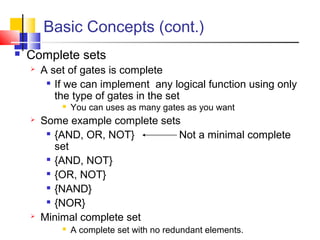
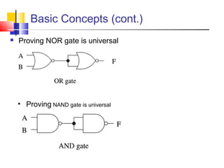
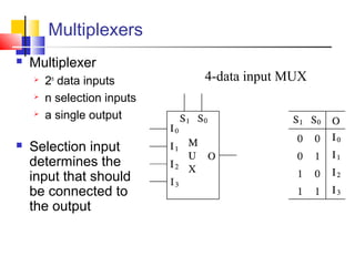
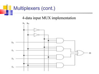
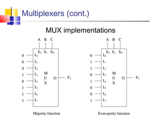
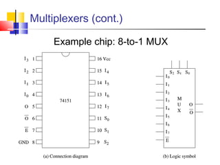
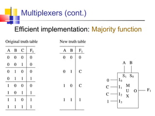
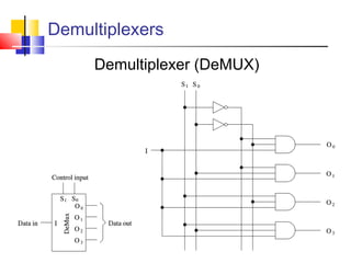
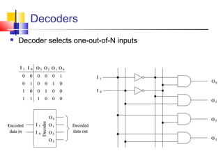
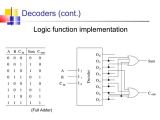
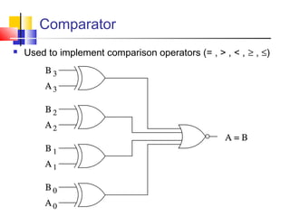

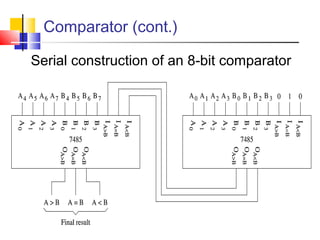
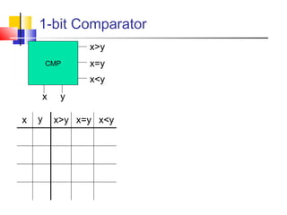
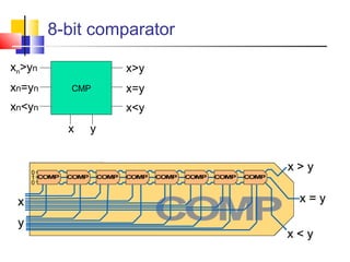
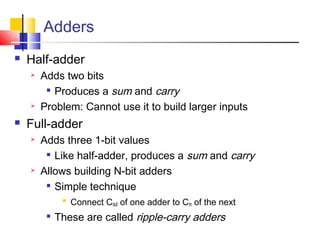
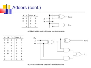
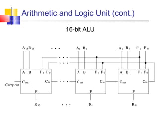
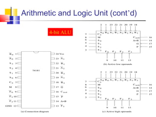

The document discusses digital logic design and covers the following topics in 3 sentences: It introduces basic concepts in digital logic like logic gates, truth tables, and complete gate sets. It then discusses combinational logic circuits like multiplexers, demultiplexers, decoders, comparators, and adders. Finally, it discusses sequential circuits and arithmetic logic units that can perform arithmetic and logical operations on binary numbers.