SlideShare a Scribd company logo
1 of 106
Download to read offline
LAUNCH PAD V User's Manual
I
Read all safety warnings and instructions.
*Note: Failure to follow the warnings and instructions may result in
electric shock, fire and/or serious injury.
1. Always perform automotive testing in a safe environment.
2. Do not connect or disconnect any test equipment while the ignition
is on or the engine is running.
3. DO NOT attempt to operate the tool while driving the vehicle.
Have second personal operate the tool. Any distraction may
cause an accident.
4. Before starting the engine, put the gear lever in the Neutral
position (for manual transmission) or in the Park (for automatic
transmission) position to avoid injury.
5. NEVER smoke or allow a spark or flame in vicinity of battery or
engine. Do not operate the tool in explosive atmospheres, such as
in the presence of flammable liquids, gases, or heavy dust.
6. Keep a fire extinguisher suitable for gasoline/chemical/electrical
fires nearby.
7. Wear an ANSI-approved eye shield when testing or repairing
vehicles.
8. Put blocks in front of the drive wheels and never leave the vehicle
unattended while testing.
9. Use extreme caution when working around the ignition coil,
distributor cap, ignition wires and spark plugs. These components
create hazardous voltage when the engine is running.
10. To avoid damaging the tool or generating false data, please make
sure the vehicle battery is fully charged and the connection to the
vehicle DLC (Data Link Connector) is clear and secure.
WARNING SYMBOLS AND DEFINITIONS
This safety alert symbol is used to alert you
to potential injury hazards. Obey all safety
messages that follow this symbol to avoid
possible injury.
Indicates an imminently hazardous situation
which, if not avoided, could result in death or
serious injury to the operator or to bystanders.
Indicates a potentially hazardous situation
which, if not avoided, could result in death or
serious injury to the operator or to bystanders.
Indicates a hazardous situation which, if not
avoided, could result in minor or moderate
injury to the operator or to bystanders.
Addresses practices not related to personal
injury.
IMPORTANT SAFETY INFORMATION
When an engine is operating, keep the service area well-ventilated
or attach a building exhaust removal system to the engine
exhaust system. Engines produce various poisonous compounds
(hydrocarbon, carbon monoxide, nitrogen oxides, etc.) that cause
slower reaction time and result in death or serious personal injury.
www.obdii365.com
II
LAUNCH PAD V User's Manual
11. Automotive batteries contain sulfuric acid that is harmful to skin.
In operation, direct contact with the automotive batteries should
be avoided. Keep the ignition sources away from the battery at all
times.
12. Keep the tool dry, clean, free from oil, water or grease. Use a mild
detergent on a clean cloth to clear the outside of the equipment
when necessary.
13. Keep clothing, hair, hands, tools, test equipment, etc. away from
all moving or hot engine parts.
14. Store the tool and accessories in a locked area out of the reach of
children.
15. Do not use the tool while standing in water.
16. Do not expose the tool or power adaptor to rain or wet conditions.
Water entering the tool or power adaptor increases the risk of
electric shock.
Table of Contents
1 Introduction......................................................................................1
1.1 Product Profile................................................................................1
1.2 Features .........................................................................................1
1.3 Technical Specifications .................................................................2
2 Components & Controls .................................................................3
2.1 Display Tablet .................................................................................4
2.2 Docking Station (Optional)..............................................................5
2.3 VCI Device......................................................................................6
2.4 Accessory Checklist........................................................................7
3 Preparations.....................................................................................9
3.1 Charging the Tablet ........................................................................9
3.2 Power ON/OFF...............................................................................9
3.3 Locator & Navigation Buttons.......................................................10
3.4 Wi-Fi Setup...................................................................................10
4 Initial Use........................................................................................11
4.1 Getting Started .............................................................................11
4.2 Register & Download Diagnostic Software...................................11
4.3 Function Modules .........................................................................13
4.4 Vehicle Menu Layout ....................................................................14
4.5 Diagnostics toolbar.......................................................................14
5 Start Diagnostics...........................................................................16
5.1 Connections..................................................................................16
5.1.1 Preparation..........................................................................16
www.obdii365.com
LAUNCH PAD V User's Manual
III
5.1.2 DLC Location.......................................................................16
5.1.3 Vehicle Connection (For Passenger Vehicle Version) .........16
5.1.3 Vehicle Connection (For Commercial Vehicle Version/Diesel
& Gasoline Version)......................................................................17
5.2 Communication Setup ..................................................................18
5.3 Start Diagnostics ..........................................................................18
5.3.1 Intelligent Diagnosis ............................................................18
5.3.2 Local Diagnosis ...................................................................20
5.4 Maintenance Reset.......................................................................31
5.4.1 Oil Reset Service.................................................................31
5.4.2 Electronic Parking Brake Reset...........................................32
5.4.3 Steering Angle Calibration...................................................32
5.4.4 ABS Bleeding.......................................................................32
5.4.5 Tire Pressure Monitor System Reset...................................32
5.4.6 Gear Learning......................................................................32
5.4.7 IMMO Service......................................................................33
5.4.8 Injector Coding ....................................................................33
5.4.9 Battery Maintenance System Reset ....................................33
5.4.10 Diesel Particulate Filter (DPF) Regeneration ....................33
5.4.11 Electronic Throttle Position Reset .....................................34
5.4.12 Gearbox Matching .............................................................34
5.4.13 AFS (Adaptive Front-lighting System) Reset ....................34
5.4.14 Sunroof Initialization ..........................................................34
5.4.15 Suspension Calibration .....................................................34
5.5 Remote Diagnosis ........................................................................35
5.5.1 Interface Layout...................................................................35
5.5.2 Add Friends .........................................................................35
5.5.3 Start Instant Messaging.......................................................36
5.5.4 Launch Remote Diagnosis (Device-To-Device)...................37
5.5.5 Launch Remote Diagnosis (Device-To-PC).........................38
5.6 Diagnostic History.........................................................................40
5.7 Software Update...........................................................................40
5.7.1 Update Diagnostic Software & APP.....................................40
5.7.2 Set Frequently Used software .............................................41
5.8 Store.............................................................................................41
5.9 ADAS............................................................................................42
5.10 Feedback....................................................................................43
6 User Info.........................................................................................44
6.1 My Report.....................................................................................44
6.2 VCI................................................................................................45
6.3 Immobilizer Programmer ..............................................................45
6.4 Activate VCI..................................................................................46
6.5 Fix connector firmware/system.....................................................46
6.6 My News.......................................................................................46
6.7 Data Stream Sample ....................................................................46
6.8 Vehicle Voltage.............................................................................46
6.9 My Order.......................................................................................46
6.10 Subscription Renewal Card........................................................46
6.11 Profile..........................................................................................46
6.12 Change Password ......................................................................47
6.13 Settings.......................................................................................47
6.13.1 Units ..................................................................................47
www.obdii365.com
IV
LAUNCH PAD V User's Manual
6.13.2 Shop Information ...............................................................47
6.13.3 Printer Set..........................................................................47
6.13.4 Clear Cache.......................................................................48
6.13.5 About .................................................................................48
6.13.6 Diagnostic Software Auto Update......................................48
6.13.7 Login/Exit from current account.........................................48
6.14 Diagnostic Software Clear..........................................................48
7 ToolBox ..........................................................................................49
7.1 Sensorbox & Multimeter (Optional) ..............................................49
7.1.1 Product summary ................................................................49
7.1.2 Components and Accessories.............................................50
7.1.3 Sensor Simulation ...............................................................51
7.1.4 Multimeter............................................................................55
7.2 Battery Tester (V1.0, Optional) .....................................................56
7.2.1 Product Summary................................................................56
7.2.2 Test Environment.................................................................57
7.2.3 Components and Accessories.............................................57
7.2.4 Connections & Operations...................................................58
7.2.5 Precautions on battery test .................................................60
7.2 Battery Detection (V2.0, Optional)................................................62
7.2.1 Product Summary................................................................62
7.2.2 Battery Health Test .............................................................64
7.2.3 Start System Test ...............................................................67
7.2.4 Charging Health Test..........................................................68
7.2.5 Reports...............................................................................70
7.3 Oscilloscope (Optional) ................................................................72
7.3.1 Introduction..........................................................................72
7.3.2 Structure & Accessories ......................................................72
7.3.3 Connection & Initial Use ......................................................75
7.3.4 Operations...........................................................................79
7.4 Ignition (Optional) .........................................................................85
7.4.1 Secondary-distributor ignition analysis................................85
7.4.2 Secondary-simultaneous ignition analysis...........................87
7.4.3 Secondary-direct ignition analysis.......................................88
7.4.4 Waveform analysis mode ....................................................89
7.5 Videoscope (Optional)..................................................................92
7.5.1 Introduction..........................................................................92
7.5.2 Components & controls .......................................................93
7.5.3 Technical Parameters..........................................................93
7.5.4 Connections & Operations...................................................94
8 Other Modules ...............................................................................95
8.1 Email.............................................................................................95
8.2 Browser ........................................................................................95
8.3 TeamViewer..................................................................................95
8.3.1 TeamViewer QuickSupport..................................................95
8.3.2 TeamViewer.........................................................................96
8.4 Wireless Upgrade.........................................................................96
8.5 Files..............................................................................................96
8.6 Gallery ..........................................................................................97
8.7 Recording Master .........................................................................97
Appendix - FAQ.................................................................................98
www.obdii365.com
LAUNCH PAD V User's Manual
1
• Remote Diagnosis: This option aims to help repair shops or
technicians launch instant messaging and remote diagnosis,
making the repair job getting fixed faster.
• Maintenance & Reset: All kinds of common maintenance and
reset items including Oil lamp reset, DPF regeneration, ABS
bleeding can be done.
• One-click Update: Lets you update your diagnostic software
online.
• Diagnostic History: Provides a quick access to the tested vehicles
and users can choose to view the test report or resume from
previous diagnostic session, without the necessity of starting
from scratch.
• Pre- and Post- Repair Result Comparison: By comparing the pre-
repair and post-repair report, you can clearly determine which
vehicle issues have been fixed and which remained unsolved.
• Diagnostic Feedback: Enables you to submit the vehicle issue to
us for analysis and troubleshooting.
• Toolbox: Scopebox, Sensorbox, Batterybox and Videoscope
(sold separately) are available for extending the functions of the
tablet.
• Vehicle Coverage: Quick dial to view the vehicle models that the
tablet covers.
2. WLAN connection is supported.
3. ADAS calibration: Optional. This function needs to be activated
before normal use and only works with the LAUNCH-specific ADAS
calibration tool.
4. Web browser: Users can make online search and visit any website.
5. File Manager: Lets you manage files or downloaded files stored in
memory card efficiently.
6. Settings: To configure your personalized tablet.
1 Introduction
1.1 Product Profile
X-431 PAD V is an evolutionary smart solution for specialized
automotive diagnosis and maintenance. It inherits from LAUNCH’s
advanced diagnosing technology and is characterized by covering a
wide range of vehicles, featuring powerful functions, and providing
precise test result.
Through the wireless communication between VCI device and the
tablet, it achieves full car model and full system vehicle trouble
diagnosis, which include Reading DTCs, Clearing DTCs, Reading
Data Stream, Actuation Test and Special Functions.
Moreover, taking advantage of the mobile Internet, it also integrates
One-click Update, Remote Diagnosis which helps to diagnose vehicle
issues more efficiently, and greatly increase customer’s retention and
boost shop revenue.
This tool adopts a higher performance-price ratio display tablet,
which comes loaded with two Wi-Fi modules, powerful 8-core 2GHz
processor, 4G RAM, and a 10.1” sunlight readable capacitive touch
screen with a resolution of 1920 x 1200 pixels.
1.2 Features
1. Diagnose:
• Smart Diagnosis: This module allows you to use the VIN
information of the currently identified vehicle to access its data
(including vehicle information, historical diagnostic records) from
the cloud server to perform quick test.
• Local Diagnosis: To perform diagnosis by executing on-screen
commands step by step. Diagnosis functions include: Read
DTCs, Clear DTCs, Read Data Stream, Special Functions etc.
www.obdii365.com
2
LAUNCH PAD V User's Manual
B. VCI Device
Item Description
Working voltage DC 9V ~ 36V
Memory 256MB
ROM 8GB
USB Type B x 1
Bluetooth BT2.1 & 4.2
WiFi 2.4G/5GHz dual frequency
1.3 Technical Specifications
A. Display Tablet
Item Description
Operating system Android
CPU 8-core processor, 2GHz
Display 10.1 inch capacitive touch screen with
1920 x 1200 resolution
Memory 4GB
Hard disk 64GB
Connectivity • Wi-Fi: 2.4G/5GHz dual frequency
• Universal serial BUS Ports (1 x
Type-C + 1 x Type-A)
Cameras 8MP front-facing camera + 13MP rear-
facing camera
Size 320mm x 211mm x 46mm
Operating
Temperature
-10℃ ~ 50℃(14 ~122℉)
Storage Temperature -20℃ ~ 70℃(-4 ~158℉)
www.obdii365.com
LAUNCH PAD V User's Manual
3
2 Components & Controls
There are three main components to the diagnostic system:
• Display Tablet -- the central processor and monitor for the system
(For details, please refer to Chapter 2.1.)
Fig. 2-1
• Docking Station -- the platform for charging the tablet and extending
functions (For details, please refer to Chapter 2.2.)
Fig. 2-2
• VCI Device -- the device for accessing vehicle data (For details,
please refer to Chapter 2.3.)
Fig. 2-3
www.obdii365.com
4
LAUNCH PAD V User's Manual
2.1 Display Tablet
Fig. 2-4 Top & front views
Table 2-1 formulates ports and indicators of display tablet:
No. Name & Descriptions
1
Memory Card Slot -- To store the memory card for storage
expansion.
2 Type C Charging Port -- Reserved for charging the tablet.
3
Power/Screen Lock Button -- To turn the tablet on/off with
long press, or lock the screen with short press.
4
Volume Buttons -- To adjust the volume.
*Note: Press and hold [POWER] and [VOL -] key to capture the
current screenshot.
5
Data I/O Port -- Reserved for add-on modules (such as
Batterybox, Scopebox and Sensorbox), and other devices
with similar port.
6 Microphone
7
Charging indicator -- It illuminates red while the tablet is
charging. Once charging is finished, it will illuminate solid
green.
8 10.1" Capacitive Touch Screen
9 Ambient Light Sensor
10 Front Camera
www.obdii365.com
LAUNCH PAD V User's Manual
5
2.2 Docking Station (Optional)
Fig. 2-6 Docking Station
Table 2-3 formulates ports of the docking station
No. Name & Descriptions
1 Charging Slot -- To charge the tablet.
2 OBD16 Socket -- To store the VCI device to avoid loss.
3
DC 5V OUT Port -- (Reserved for charging other USB
devices only.)
4
Type C Charging Port -- Use the power adaptor to supply
power to the docking station through connection to AC
outlet.
5
Power LED -- Illuminates solid green when it is powered
up.
Fig. 2-5 Rear view
Table 2-2 formulates parts of display tablet (rear):
No. Name & Descriptions
11 Rear Camera
12 Camera Flash
13 Audio Speaker
14 Charging Slot
15
Adjustable Kickstand - Flip out it to any angle and work
comfortable at your desk, or hang it on automotive part.
www.obdii365.com
6
LAUNCH PAD V User's Manual
2.3 VCI Device
The VCI device works as a vehicle communication interface device,
which is used to connect to the vehicle’s DLC (Data Link Connector)
socket via OBD II extension cable to read the vehicle data and then
send it to the tablet via Wi-Fi or data cable.
Fig. 2-7 VCI device
Table 2-4 formulates ports and indicators of VCI device:
No. Name & Descriptions
1
OBD II-16 Diagnostic Connector -- Use the OBD II
extension cable to connect VCI device to the vehicle’s
OBDII DLC.
2
LED Indicators -- It is defined as follows:
• Power: It illuminates solid red when the module is
powered on.
• Vehicle: While communicating with the vehicle, the
indicator lights up and flashes. Otherwise, it will not
illuminate.
• BT: It illuminates when the VCI device is working in
Bluetooth communication mode.
• I/O: It lights up when the VCI device is connected to the
tablet via data cable.
• Wireless: It illuminates when the VCI device is working
in Wi-Fi communication mode.
3 Reset Hole -- To reset the VCI device.
4
Data I/O port -- For connecting the VCI device to the
tablet via data cable to perform vehicle diagnosis.
5 DC-IN power jack -- For connecting the power adaptor.
www.obdii365.com
LAUNCH PAD V User's Manual
7
2.4 Accessory Checklist
Common accessories are same, but for different destinations, the
accessories (such as diagnostic software, testing connectors) may
vary. Please consult from the local agency or check the package list
supplied with this tool together.
Table 2-5 -- Common accessories and descriptions
No. Name Qt. Picture
1 Display Tablet 1
2 VCI Device 1
(To connect to vehicle’s DLC.)
3 Docking Station 1
(Optional. To charge the tablet.)
4
Cigarette Lighter
Cable
1
(To supply power to non-16pin
dongle via vehicle’s cigarette
lighter receptacle.)
5 Power Adaptor 1
(To charge the tablet.)
6
Cigarette Lighter
Cable
1
(To provide power to the non-16
pin dongle through connection to
the Cigarette Lighter receptacle.)
7
Battery Clamps
Cable
1
(To provide power to the non-16
pin dongle through connection to
the vehicle's battery.)
www.obdii365.com
8
LAUNCH PAD V User's Manual
8
OBD II extension
cable
1
(To connect the VCI device for
extension purpose.)
9 OBD I Adaptor 1
(A adaptor cable for connecting
non-16 pin dongle.)
10
Password
Envelope
1
(A piece of paper bearing
Product S/N and Activation
Code, which is required for your
registration.)
11
Non-16pin
Connector Kit
(Optional)
www.obdii365.com
LAUNCH PAD V User's Manual
9
3 Preparations
3.1 Charging the Tablet
*Notes:
• Only use the included power adaptor to recharge the tablet. Use of any
other adaptor will damage the tool. We assume no responsibility for
damage or loss resulting from using other similar adaptors other than the
specified one.
• Always charge on a non-flammable surface in a well-ventilated area.
1. To check the battery power
level, press and hold the Power
button about 3 seconds to turn
on the tablet.
2. Power level is indicated as
a percentage in the upper
right corner of the screen.
If the power level drops
below 10% while the tablet
is on, a "Connect Charger"
notification will appear on the
screen.
A. Charging with the Included 5V Power Adaptor
1. Connect one end of the power
adaptor to Type C charging port
of the tablet, and the other end
to the AC outlet.
2. The charging LED illuminates
solid red and the charging sym-
bol will apeear on the screen.
3. Once it illuminates solid
green, it indicates that the
battery is fully charged and
the charging complete sym-
bol replaces the charging
symbol. Disconnect the pow-
er adaptor from the AC outlet.
B. Charging with the Docking Station
1. Locate the charging slot on the
bottom of the tablet and docking
station.
3. Insert one end of the included
power cord to the charging port
of the docking station, then the
other end into the AC outlet.
The charging LED illuminates
solid red while charging and the
charging symbol will apeear
on the screen.
2. Align the charging slots, and
then dock the tablet into the
station to ensure that it is
firmly seated on the docking
station.
4. Once it illuminates solid
green, it indicates that the
battery is fully charged and
the charging complete sym-
bol replaces the charging
symbol. Disconnect the dock-
ing station from the AC outlet.
3.2 Power ON/OFF
*Note: If it is the first time you use the tablet or the tablet keeps idle for a
long time, it could fail to be turned on. It results from low battery. In this case,
please recharge it for a while and try to turn it on.
1. Press and hold the POWER but-
ton for about 3 seconds to turn
on the tablet. The system starts
initializing and then enters the
Home screen.
2. To turn the tablet off, press
and hold the POWER button
until an option menu appears.
Tap "Power Off".
www.obdii365.com
10
LAUNCH PAD V User's Manual
3.3 Locator & Navigation Buttons
1 2 3 4 5 6
Fig. 3-1
On-screen keys and status bar are as follows:
1 Tap to visit the Launch’s official website.
2
Tap to capture the current screen and all captured
screenshots are stored in the Screenshots folder.
3
: Shows whether the VCI device is properly connected or
not.
4
Tap to display a list of applications that are currently
running or recently used. To open an application, tap it. To
remove an application, swipe it upwards.
5 Tap to navigate to the Android System’s home screen.
6 Tap to return to the previous screen or exit the application.
3.4 Wi-Fi Setup
The tablet has dual built-in Wi-Fi communication modules. One is
used to communicate with the tablet, and the other allows the tablet
to get online. Once you’re online, you can register your tool, update
diagnostic software & APK, browse the Internet, get apps and send
email on your network.
If the VCI device is successfully activated, the tablet will automatically
connect to the VCI device. In this case it is not necessary for the user
to manually configure it again.
*Note: Once WLAN is set as ON, the tablet will consume more power. While
it keeps unused, please set it off to save power. While WLAN is not in use,
please turn it off to conserve battery power.
Connect to a Wi-Fi Network
1. On the Home screen, tap Tablet
Settings > WLAN.
2. Move the Wi-Fi switch to ON,
the tablet starts searching for
available wireless LANs.
3. Select the desired Wi-Fi net-
work from the list. If the cho-
sen network is open, you can
connect directly. A password
may be required for secured
networks.
Disconnect from a Wi-Fi Network
1. On the Home screen, tap Tablet
Settings > WLAN.
2. Tap the network with a “Con-
nected” status, then tap “For-
get”.
www.obdii365.com
LAUNCH PAD V User's Manual
11
4 Initial Use
4.1 Getting Started
For new users, please follow the operation chart shown in Fig. 4-1 to
get familiar with and start using this tool.
Tap “
Diagnose”
Select vehicle
Select test system
Select test function
Select diagnostic
software version
Tap “Login” to
register
Is VCI
connector
activated ?
No
Download/Update
diagnostic software
Yes
…… (Refer to
Chapter 4.2)
Register & Activate
OK
Fig. 4-1
*Note: Before registering, please make sure that the tablet has a strong and
stable Wi-Fi signal.
4.2 Register & Download Diagnostic Software
On the home screen, tap the application icon to launch it, and then tap
“Login” to enter the login interface of diagnosis software.
Fig. 4-2
(If you are a new user, follow A to proceed.)
(If you have registered to be a member, go to B to login the system directly.)
(In case you forgot password, refer to C to reset a new password.)
A. If you are a new user, tap “New Registration” to enter registration
page. See Fig. 4-3.
Fig. 4-3
In Fig. 4-3, fill in the information in each field (Items with * must be
filled). After inputting, tap “Register”, a screen similar to the following
www.obdii365.com
12
LAUNCH PAD V User's Manual
will appear:
Fig. 4-4
In Fig. 4-4, input the Serial Number and Activation Code, which can be
found in the password envelope.
Fig. 4-5
*Note: To exit and activate it later, tap “Skip”. In this case, you can activate
your connector by tapping “Activate VCI” under the “User Info” tab.
Tap “Activate” to finish your registration. See Fig. 4-6.
Fig. 4-6
To download the diagnostic software, tap “Yes” to enter the download
page. Tap “No” to download and install it later.
On download page, tap “Update” to start downloading. To pause
downloading, tap “Stop”. To resume it, tap “Continue”. Once download
is complete, the system will install the software package automatically.
*Notes:
• In process of download, please make sure the tablet has a strong Wi-Fi
signal. It may take several minutes to finish it, please be patient to wait.
• To use the AutoDetect (VINScan) function, you have to download the
corresponding diagnostic software and AutoSearch file.
B. If you have registered to be a member, input your name and
password, and then tap the “Login” button to enter the main menu
screen directly.
*Note: The tablet has an auto-save function. Once the username and
password are correctly entered, the system will automatically store it.
Next time you login the system, you will not be asked to input the account
manually.
C. If you forgot the password, tap “Retrieve password” and then follow
on-screen instructions to set a new password.
www.obdii365.com
LAUNCH PAD V User's Manual
13
4.3 Function Modules
Fig. 4-7
It mainly includes the following items:
Intelligent Diagnose
This module allows you to obtain vehicle data
from the cloud server to perform quick test via
reading VIN, which provides a perfect solution
to various defects resulting from step-by-
step menu selection. In addition, user can
also check the historical repair records online
through this module.
Local Diagnose To diagnose a vehicle manually.
ADAS
This function enables users to perform
ADAS (Advanced Driver Assistance System)
calibration operations. The ADAS calibration
software is disabled by default. Before using
this function, users must activate the ADAS
function using the ADAS Activation Card.
Software Update
To update vehicle diagnostic software and
APK.
Remote Diagnose
This option aims to help repair shops or
technicians launch instant messaging and
remote diagnosis, making the repair job
getting fixed faster.
Reset
To perform all kinds of common repair &
maintenance items, including electronic
throttle position reset, ABS bleeding, DPF
regeneration, oil lamp reset etc.
*Note: This module only applies to Passenger
Vehicle /Gasoline & Diesel Version.
Feedback
To feed back the recent 20 diagnostic logs to
us for issue analysis.
Maintenance
Abundant maintenance data are available,
which helps repair professionals diagnose
and repair vehicles efficiently, accurately and
profitably.
Toolbox
Includes Camera, Browser, Oscilloscope,
Ignition, Sensor, Multimeter, Battery etc.
User Info
To manage VCI, diagnostic reports & records,
change password, configure Wi-Fi printer,
sample data and logout / login etc.
Vehicle Coverage
To check the vehicle models supported on the
tablet.
Tablet Setting Configures the system setting of the tablet.
www.obdii365.com
14
LAUNCH PAD V User's Manual
1
VINScan button: Tap it to scan the Vehicle Identification
Number (VIN) code of your vehicle. OBD VIN and INPUT VIN
are included. This function does not apply to the commercial
vehicles.
*Note: Before using this function, the corresponding diagnostic
software and Auto search file need to be downloaded on your tool
first while downloading the diagnostic software.
2 All Tab: Displays all the vehicle makes in the vehicle menu.
3 Common Tab: Displays all frequently-used vehicle makes.
4
Regional buttons: Tap different buttons to switch to
corresponding vehicles.
5
HD: If you have purchased a Gasoline & Diesel Version and
activated it, this tab will appear.
6
History Button: Generally once a vehicle diagnosis is
performed, the tablet will record the every details of diagnostic
process. This function provides a quick access to the
previously tested vehicles. Testing can be resumed from the
previous operation without starting from scratch.
7
Store: Allows you to renew the subscription of diagnostic
software and check the order status.
8
Search bar: Input the desired vehicle model to quickly locate
it.
4.5 Diagnostics toolbar
The diagnostics toolbar contains a number of buttons that allow you
to print the displayed data or make other controls. It is displayed on
Other Modules
Includes TeamViewer, Email, Browser,
Wireless Upgrade and FAQ etc.
4.4 Vehicle Menu Layout
After downloading the diagnostic software, you can go to “Local
Diagnose” to check if all software are completely downloaded and
installed.
Tap “Local Diagnosis”, a screen similar to the following figure appears:
1 2 3 4 5 6 7 8
Fig. 4-8
www.obdii365.com
LAUNCH PAD V User's Manual
15
the upper right corner of the screen and goes through the whole
diagnostic session. The table below provides a brief description for the
operations of the diagnostics toolbar buttons:
Home Tap to navigate to the home screen.
Print
Tap to print the current screen.
To perform printing, you need to purchase an
extra Wi-Fi printer separately.
Exit Session Tap to exit the current diagnostic session.
www.obdii365.com
16
LAUNCH PAD V User's Manual
5 Start Diagnostics
5.1 Connections
5.1.1 Preparation
Normal testing conditions
• Turn on the vehicle power supply.
• Vehicle battery voltage range should be 9-18V or 11-36V and
working voltage of the tablet is 5V.
• Throttle should be closed at its close position.
• Ignition timing and idle speed should be within specified range;
water and transmission oil temperature are within normal working
range (water temperature is 90-110℃ and transmission oil
temperature is 50-80℃).
Select testing connectors/adaptor cables
If the tablet is testing vehicles equipped with universal OBD II 16 PIN
diagnostic socket, please use the included VCI device. (For vehicles
with non-OBD II 16 PIN diagnostic socket, a non-16 PIN dongle is
required.)
5.1.2 DLC Location
For Passenger Vehicles, the DLC (Data Link Connector or Diagnostic
Link Connector) is the standardized 16-cavity connector where
diagnostic code readers interface with the vehicle’s on-board
computer. The DLC is usually located 12 inches from the center of the
instrument panel (dash), under or around the driver’s side for most
vehicles. If Data Link Connector is not located under dashboard, a
label should be there telling location. For some Asian and European
vehicles, the DLC is located behind the ashtray and the ashtray must
be removed to access the connector. If the DLC cannot be found, refer
to the vehicle’s service manual for the location.
Fig. 5-1
For Commercial Vehicles, the DLC is located in the driver’s cab.
5.1.3 Vehicle Connection (For Passenger Vehicle Version)
The method used to connect the VCI device to a vehicle’s DLC
depends on the vehicle’s configuration as follows:
• A vehicle equipped with an OBD II management system supplies
both communication and 12V power through a standardized DLC.
• A vehicle not equipped with an OBD II management system
supplies communication through a DLC connection, and in some
cases supplies 12V power through the cigarette lighter receptacle
or a connection to the vehicle battery.
Follow the steps mentioned below to connect OBD II vehicle:
1. Locate vehicle’s DLC socket.
2. Use the OBD II extension cable to connect the VCI device to the
vehicle’s DLC socket.
3. Choose one of the two ways to obtain power from:
A. Power adaptor: Connect one end of the included power adaptor
to Power interface of the tablet, and the other end to AC outlet.
B. Internal battery pack: For details on how to recharge the tablet,
see “Chapter 3.1 Charging the tablet”.
www.obdii365.com
LAUNCH PAD V User's Manual
17
For non-OBDII vehicle, proceed as follows:
1. Locate vehicle’s DLC socket.
2. Select the corresponding non-16pin dongle.
3. Plug the non-16pin end of the non-16pin adaptor into the DLC
socket, then connect the other end to the OBD I adaptor, and then
tighten the captive screws.
4. Connect the other end of the adaptor to the included VCI device.
5. To supply power to OBD I adaptor from:
A. Cigaretter Lighter: Connect one end of the cigarette lighter cable
to vehicle’s cigarette lighter receptacle, and the other end to the
DC-IN jack of the VCI device.
VCI device
Cigarette lighter
OBD I adaptor Non-16pin adaptor
To vehicle's DLC
To Cigarette lighter receptacle
Fig. 5-2
B. Battery Clamps Cable: Connect one end of the battery clamps
cable to vehicle’s battery, and the other end to the power jack of
OBDI adaptor.
VCI device
Battery clamps cable
OBD I adaptor Non-16pin adaptor
To vehicle's DLC
To vehicle's battery
Fig. 5-3
5.1.3 Vehicle Connection (For Commercial Vehicle Version/
Diesel & Gasoline Version)
The method used to connect the VCI device to a vehicle’s DLC
depends on the vehicle’s configuration as follows:
For OBD II vehicle, directly plug the VCI device into the vehicle’s DLC
(OBD II extension cable is recommended).
For non-OBD II vehicle, follow either of the ways to proceed:
1. Locate vehicle’s DLC socket.
2. Select the corresponding non-16pin dongle.
3. Plug the non-16pin end of the non-16pin adaptor into the DLC
socket, then connect the other end to the OBD II extension cable.
4. Connect the other end of the adaptor to the included VCI device.
5. To supply power to OBD I adaptor from:
A. Cigaretter Lighter: Connect one end of the cigarette lighter cable
to vehicle’s cigarette lighter receptacle, and the other end to the
DC-IN jack of the VCI device.
www.obdii365.com
18
LAUNCH PAD V User's Manual
VCI device
Cigarette lighter
OBD II extension cable Non-16pin adaptor
To vehicle's DLC
To Cigarette lighter receptacle
Fig. 5-4
B. Battery clamps cable: Connect one end of the battery clamps
cable to vehicle’s battery (Red to + & Black to - ), and the other end
to the DC-IN jack of the VCI device.
VCI device
Battery clamps cable
OBD II extension cable Non-16pin adaptor
To vehicle's DLC
To vehicle's battery
Fig. 5-5
5.2 Communication Setup
There are two kinds of ways available for the tablet to communicate
with the VCI device: Wi-Fi and USB cable.
After the sign-up is successfully completed, the Wi-Fi communication
between the tablet and the VCI device is automatically done and user
has no need to configure it again.
The USB cable connection is a simple & quick way to establish
communication between the tablet and the VCI module. After
properly connecting the USB cable from the tablet to the VCI, the VCI
navigation button at the bottom of the screen becomes highlighted
indicating the USB connection is successful.
*Note: The USB connection provides the most stable and fastest
communication. When all communication methods are applied at the same
time, the tablet will use the USB communication as the default priority.
5.3 Start Diagnostics
5.3.1 Intelligent Diagnosis
Through simple Wi-Fi communication between the tablet and VCI, you
can easily get the VIN (Vehicle Identification Number) information of
the currently identified vehicle. Once the VIN is successfully identified,
the system will retrieve it from the remote server and then guide you to
vehicle information page without the necessity of step-by-step manual
menu selection.
The vehicle information page lists all historical diagnostic records of
the vehicle, which lets the technician have a total command of the
vehicle faults. In addition, a quick dial to local diagnosis and diagnostic
function are also available on this page for reducing the roundabout
time and increasing productivity.
*Notes:
• Before using this function, please make sure the VCI is properly
connected to the vehicle’s DLC. For detailed connection, see Chapter
5.1.3 “Vehicle Connection”.
• A stable network connection is required for this function.
Follow the steps below to proceed.
1. Tap “Intelligent Diagnose” on the Job Menu to enter Fig. 5-6.
www.obdii365.com
LAUNCH PAD V User's Manual
19
Fig. 5-6
2. After pairing is complete, the handset starts reading the vehicle
VIN.
A. If the VIN can be found from the remote server database, a screen
similar to the following figure displays:
Fig. 5-7
• Tap “Diagnostic” to start a new diagnostic session.
• Tap “Scan History” to view its historical repair record. If there are
records available, it will be listed on the screen in sequence of date.
If no records exist, the screen will show “No Record”.
Fig. 5-8
• Tap “View record” to view the details of the current diagnostic
report.
• To perform other functions, tap “Quick access” to directly go to
the function selection screen. Choose the desired one to start a
new diagnostic session.
B. If the handset failed to access the VIN information, the screen will
display as below:
Fig. 5-9
www.obdii365.com
20
LAUNCH PAD V User's Manual
In this mode, you need to input the VIN manually or tap to scan it.
1) Tap to launch the VIN recognition module.
Fig. 5-10
Place the VIN inside the viewfinder rectangle to scan it. The most
recognizable location for this number is in the top left corner on the
vehicle’s dashboard. Other locations include the driver’s door or post,
and the firewall under the hood.
• To switch the display orientation, tap .
• To turn the flash on, tap .
• If you have scanned the VIN of the vehicle, tap to choose it from
the record list.
• In case the handset failed to detect it, tap to enter it manually.
• Tap to switch the camera to barcode pattern recognition mode.
• indicates the camera is in character pattern recognition mode
(default mode).
After scanning, the screen automatically displays the result.
Fig. 5-11
• If the VIN scanned is incorrect, tap the result field to modify it and
then tap “OK”. If the VIN exists on the remote server, the system
will enter the vehicle information screen. See Fig. 5-8.
• To scan it again, tap “REPEAT”.
2) Input the VIN, and tap “OK”, the system will automatically identify
the vehicle model and directly navigate to the vehicle information
page.
*Note: In general, vehicle identification numbers are standardized - all
contain 17 characters. VIN characters may be capital letters A through Z
and numbers 1 through 0; however, the letters I, O and Q are never used in
order to avoid mistakes of misreading. No signs or spaces are allowed in the
VIN.
5.3.2 Local Diagnosis
Tap “Local Diagnose” to enter the vehicle selection page.
2 approaches are provided for you to access the vehicle diagnostic
software. Choose any one of the following ways:
1. VINSCAN
This function enables you to access it more quickly.
www.obdii365.com
LAUNCH PAD V User's Manual
21
• To switch the display orientation, tap .
• To turn the flash on, tap .
• If you have scanned the VIN of the vehicle, tap to choose it
from the record list.
• In case the handset failed to detect it, tap to enter it manually.
• Tap to switch the camera to barcode pattern recognition
mode.
• indicates the camera is in character pattern recognition
mode (default mode).
Once the test vehicle is successfully identified, the tablet will jump
to the function selection page directly.
Tap the desired option to perform the corresponding function.
*Note: Before using this function, the corresponding diagnostic software
and Auto search file need to be downloaded on your tool first while
downloading the diagnostic software.
B. INPUT VIN: In this mode, you need to input the VIN manually.
In general, vehicle identification numbers are standardized - all
contain 17 characters. VIN characters may be capital letters A
through Z and numbers 1 through 0; however, the letters I, O and Q
are never used in order to avoid mistakes of misreading. No signs
or spaces are allowed in the VIN.
Tap “INPUT VIN” and a screen similar to Fig. 5-14 will appear:
Fig. 5-14
In this case, automatic scan (OBD VIN) and manual input (INPUT VIN)
are available.
Tap “VINScan”, the screen displays as follows:
Fig. 5-12
A. Camera Scan: In this mode, the VCI device should be plugged into
the vehicle’s DLC.
Tap “Camera Scan”, a screen similar to the following appears:
Fig. 5-13
Place the VIN inside the viewfinder rectangle to scan it. The most
recognizable location for this number is in the top left corner on the
vehicle’s dashboard. Other locations include the driver’s door or
post, and the firewall under the hood.
www.obdii365.com
22
LAUNCH PAD V User's Manual
Input the VIN, and tap “Confirm”, the system will automatically
identify the vehicle model and directly navigate to the function
selection page.
2. Manual Selection
Tap a corresponding diagnostic software logo, and then follow the on-
screen instruction to access the diagnostic software.
Take Demo as an example to demonstrate how to diagnose a vehicle.
1). Select diagnostic software version: Tap the “DEMO” to go to Step
2. (*Note: If more than one version is available on this tablet, it will be
listed on the screen.)
Fig. 5-15
On-screen Buttons:
Vehicle Coverage: Tap to view the vehicle models that the current
diagnostic software covers.
What’s new: Tap to view the optimized items and enhancements.
Introduction: Tap to check the software function list.
Note: Tap to read some precautions on using the current diagnostic
software.
OK: Tap it to go to next step.
2). Select test item: Select the desired test item to proceed.
Fig. 5-16
5.3.2.1 Health Report (Quick Test)
This function varies from vehicle to vehicle. It enables you to quickly
access all the electronic control units of the vehicle and generate a
detailed report about vehicle health.
Tap “Health Report”, the system starts scanning the ECUs. Once the
scanning is complete, a screen similar to the following appears:
Fig. 5-17
In Fig. 5-17, the tested system with fault code appears in red and the
system with OK displays in white (normally).
www.obdii365.com
LAUNCH PAD V User's Manual
23
*Note: Diagnostic Trouble Codes or Fault Codes can be used to identify
which engine systems or components that are malfunctioning. Never
replace a part based only on the DTC definition. Retrieving and using
DTCs for troubleshooting vehicle operation is only one part of an overall
diagnostic strategy. Follow testing procedures (in vehicle’s service manual),
instructions and flowcharts to confirm the locations of the problem.
On-screen Buttons:
: Tap to display the details of DTCs existing in the current system.
Tap to hide it.
Highlight certain DTC item, and tap to open the browser to retrieve
it in Google engine.
Fig. 5-18
Enter: Tap to select other test functions.
Fig. 5-19
Report: Tap to save the diagnostic result as a report.
Fig. 5-20
www.obdii365.com
24
LAUNCH PAD V User's Manual
*Note: Diagnostic report is classified into three categories: Pre-Repair
report, Post-Repair report and Diagnostic Scan. No matter which type you
saved the report as, the report type will be appended as a tag on the upper
right corner of the diagnostic report for easier identification.
Tap to select the report type from the option list and input the
required information, and then tap “OK”.
*Note: To facilitate the comparison of the pre-repair and post-repair reports
and get accurate test result, please make sure you saved the right type of
the diagnostic report.
To save the report as a common diagnostic report, select “Diagnostic
Scan”.
Fig. 5-21
Enter the technician and customer name and then tap “OK” to confirm
and navigate to the report details page.
*Note: For workshop information, tap “Change” to revise it. Alternatively you
can also set it in “User Info” -> “Settings” -> “Print Information”.
Once you configured the information, it will be automatically generated
every time you saved the diagnostic report. All vehicle and workshop
information will be appended as tags on the diagnostic report.
To ignore the workshop information, tap “Skip” to go to the report
details page.
On the report details page, tap “Save” to save it. All diagnostic reports
can be accessed from “User Info” -> “My Reports” -> “Health Report”.
Help: Tap to view the help information of the selected DTC item.
Compare Results: Tap to select the pre-repair report to compare. By
comparison of the pre- and post- repair reports, you can easily identify
which DTCs are cleared and which remain unfixed.
www.obdii365.com
LAUNCH PAD V User's Manual
25
The DTC status
of post-repair
The DTC status
of pre-repair
Fig. 5-22
*Note: Before performing this function, please make sure that:
• You have saved a pre-repair report of the currently tested vehicle, and
• You have already made some repairs and service and cleared the DTCs
after the pre-repair reported is generated. Otherwise, no differences exist
between the pre- and post- repair reports.
Clear DTC: Tap to clear the existing diagnostic trouble codes.
*Note: Clearing DTCs does not fix the problem(s) that caused the code(s) to
be set. If proper repairs to correct the problem that caused the code(s) to be
set are not made, the code(s) will appear again and the check engine light
will illuminate as soon as the problem that cause the DTC to set manifests
itself.
5.3.2.2 System Scan
This option allows you to quickly scan which systems are installed on
the vehicle.
In Fig. 5-16, tap “System Scan”, the system starts scanning the
systems. Once the scanning is complete, the screen will display the
result.
Fig. 5-23
Tap the desired system to advance to the test function selection
page. For detailed operations on test function, please refer to Chapter
5.3.2.3.
5.3.2.3 System Selection
This option allows you manually select the test system and function
step by step.
In Fig. 5-16, tap “System Selection”, the screen displays as follows:
www.obdii365.com
26
LAUNCH PAD V User's Manual
Fig. 5-24
Swipe the screen from the bottom to view the vehicle system on the
next page.
Tap the desired system (take “ECM” for example) to jump to the test
function page.
Fig. 5-25
*Note: Different vehicle has different diagnostic menus.
A. Version Information
This function is used to read the version information of system mode,
vehicle VIN, software and ECU.
In Fig. 5-25, tap “Version Information”, the screen displays as follows:
Fig. 5-26
Tap “OK” to confirm and exit.
B. Read Fault Code
This function displays the detailed information of DTC records
retrieved from the vehicle’s control system.
In Fig. 5-25, tap “Read Fault Code”, the screen will display the
diagnostic result.
Fig. 5-27
www.obdii365.com
LAUNCH PAD V User's Manual
27
*Note: Retrieving and using DTCs for troubleshooting vehicle operation
is only one part of an overall diagnostic strategy. Never replace a part
based only on the DTC definition. Each DTC has a set of testing procedures,
instructions and flow charts that must be followed to confirm the location of
the problem. This information can be found in the vehicle’s service manual.
On-screen Buttons:
Freeze Frame: When an emission-related fault occurs, certain vehicle
conditions are recorded by the on-board computer. This information
is referred to as freeze frame data. Freeze frame data includes a
snapshot of critical parameter values at the time the DTC is set.
Help: Tap to view the help information.
Code Search: Tap it to search for more information about the current
DTC online.
Report: To save the current data in text format. All diagnostic reports
can be accessed from “User Info” -> “My Reports” -> “Diagnostic
Report”.
C. Clear Fault Code
After reading the retrieved codes from the vehicle and certain repairs
have been carried out, you can use this function to erase the codes
from the vehicle. Before performing this function, please be sure the
vehicle’s ignition key is in the ON position with the engine off.
Clearing DTCs does not fix the problem(s) that caused the code(s) to
be set. If proper repairs to correct the problem that caused the code(s)
to be set are not made, the code(s) will appear again and the check
engine light will illuminate as soon as the problem that cause the DTC
to set manifests itself.
In Fig. 5-25, tap “Clear Fault Code”, a confirmation dialog box pops up
on the screen. Tap “Yes” and the system will automatically delete the
currently existing trouble code.
*Note: After clearing, you should retrieve trouble codes once more or turn
ignition on and retrieve codes again. If there are still some trouble codes in
the system, please troubleshoot the code using a factory diagnosis guide,
then clear the code and recheck.
D. Read Data Stream
This option lets you view and capture (record) real-time Live Data.
This data including current operating status for parameters and/or
sensor information can provide insight on overall vehicle performance.
It can also be used to guide vehicle repair.
*Note: If you must drive the vehicle in order to perform a troubleshooting
procedure, always have a second person help you. Trying to drive and
operate the diagnostic tool at the same time is dangerous, and could cause
a serious traffic accident.
In Fig. 5-25, tap “Read Data Stream”, the system will display data
stream items.
Fig. 5-28
www.obdii365.com
28
LAUNCH PAD V User's Manual
On-screen Buttons:
Select All: Tap it to select all items of the current page. To select
certain data stream item, just check the box before the item name.
Unselect: Tap it to deselect all data stream items.
OK: Tap it to confirm and jump to the next step.
After selecting the desired items, tap “OK” to enter the data stream
reading page.
Fig. 5-29
*Notes:
1. If the value of the data stream item is out of the range of the standard
(reference) value, the whole line will display in red. If it complies with the
reference value, it displays in blue (normal mode).
2. The indicator 1/X shown on the bottom of the screen stands for the
current page/total page number. Swipe the screen from the right/left to
advance/return to the next/previous page.
There are 3 types of display modes available for data viewing, allowing
you to view various types of parameters in the most suitable way.
• Value – this is the default mode which displays the parameters in
texts and shows in list format.
• Graph – displays the parameters in waveform graphs.
• Combine – this option is mostly used in graph merge status for data
comparison. In this case, different items are marked in different
colors.
On-screen Buttons:
: Tap it to view the waveform graph of the current data stream item.
Fig. 5-30
• Min/Max: Tap to define the maximum/minimum value. Once the
value goes beyond the specified value, the system will alarm.
*Note: The real time (Live Data) vehicle operating information (values/status)
that the on-board computer supplies to the tool for each sensor, actuator,
switch, etc. is called Parameter Identification Data (PID).
Graph: Tap it to view the waveform.
www.obdii365.com
LAUNCH PAD V User's Manual
29
Fig. 5-31
• Combine: This option is mostly used in graph merge status for
data comparison.
Fig. 5-32
• Value: Tap to display the parameters in texts.
• Customize: Tap , a pull-down list of the data stream items
appears on the screen. Select (Maximum 8 data stream items
can be selected)/deselect the desired items and then screen
will display/remove the waveforms corresponding to these items
immediately.
Fig. 5-33
Select Sample DS: Tap it to select the sample DS file, the values you
customized and saved in process of DS sampling will be imported into
the “Standard Range”(See below) column for your comparison.
*Note: Before executing this function, you have to sample the values of data
stream items and save it as an sample DS file.
www.obdii365.com
30
LAUNCH PAD V User's Manual
Fig. 5-34
Report: To save the current data as a diagnostic report. All diagnostic
reports can be accessed from “User Info” -> “My Reports” -> “Health
Report”.
Record: Tap to start recording diagnostic data. Recorded live data can
serve as valuable information to help you in troubleshooting of vehicle
problems. All diagnostic records can be replayed from “User Info” ->
“My Reports” -> “Recorded Data”.
*Note: The saved file follows the naming rule: It begins with vehicle type,
and then the product S/N and ends with record starting time (To differentiate
between files, please configure the accurate system time).
Help: Tap to view the help information.
Sample DS: This item enables you to customize the standard range
of live data stream items and save it as DS sample file. Each time you
run the data stream items, you can call out the corresponding sample
data to overwrite the current standard range.
Tap it to start recording the sample data (*Only data stream items with
measurement units will be recorded), and the screen displays as below:
Fig. 5-35
Once recording is complete, tap to stop it and navigate to the data
revision screen.
Fig. 5-36
Tap the Min./Max. value to change it. After modifying all desired items,
tap “Save” to save it as a sample DS file. All DS files are stored under
the “Data Stream Sample” file in “User Info.”.
E. Actuation Test
This option is used to access vehicle-specific subsystem and
component tests. Available test vary by vehicle manufacturer, year,
and model. During the actuation test, the tablet outputs commands
to the ECU in order to drive the actuators, and then determines
the integrity of the system or parts by reading the ECU data, or by
monitoring the operation of the actuators, such as switching a injector
between two operating states.
In Fig. 5-25, tap “Actuation Test”, the system will display as follows:
www.obdii365.com
LAUNCH PAD V User's Manual
31
Fig. 5-37
Simply follow the on-screen instructions and make appropriate
selections to complete the test. Each time when an operation is
successfully executed, “Completed” displays.
5.4 Maintenance Reset
In addition to amazing & powerful diagnostic function, the tablet also
features various service functions. The most commonly performed
service functions contain:
• Oil Reset Service
• Electronic Parking Brake Reset
• Steering Angle Calibration
• ABS Bleeding
• TPMS (Tire Pressure Monitor System) Reset
• Gear Learning
• IMMO Service
• Injector Coding
• Battery Maintenance System
• Diesel Particulate Filter (DPF) Regeneration
• Electronic Throttle Position Reset
• Gearbox Matching
• AFS (Adaptive Front-lighting System) Reset
• Sunroof Initialization
• Suspension Calibration
There are two methods to reset service lamp: Manual reset or Auto
reset. Auto reset follows the principle of sending command from the
tool to vehicle’s ECU to do resetting. While using manual reset, users
just follow the on-screen instructions to select appropriate execution
options, enter correct data or values, and perform necessary actions,
the system will guide you through the complete performance for
various service operations.
Select “Reset”
Select the desired reset
item (e.g. oil lamp reset
etc.)
Select the car brand
Select the service mode
(The available mode varies
from vehicle to vehicle)
Follow the instructions
on the screen to operate
Figure 5-3
5.4.1 Oil Reset Service
This function allows you to perform reset for the engine oil life system,
which calculates an optimal oil life change interval depending on the
www.obdii365.com
32
LAUNCH PAD V User's Manual
vehicle driving conditions and climate.
This function can be performed in the following cases:
1. If the service lamp is on, you must provide service for the car. After
service, you need to reset the driving mileage or driving time so that
the service lamp turns off and the system enables the new service
cycle.
2. After changing engine oil or electric appliances that monitor oil life,
you need to reset the service lamp.
5.4.2 Electronic Parking Brake Reset
1. If the brake pad wears the brake pad sense line, the brake pad
sense line sends a signal sense line to the on-board computer to
replace the brake pad. After replacing the brake pad, you must
reset the brake pad. Otherwise, the car alarms.
2. Reset must be performed in the following cases:
a) The brake pad and brake pad wear sensor are replaced.
b) The brake pad indicator lamp is on.
c) The brake pad sensor circuit is short, which is recovered.
d) The servo motor is replaced.
5.4.3 Steering Angle Calibration
To reset the steering angle, first find the relative zero point position for
the car to drive in straight line. Taking this position as reference, the
ECU can calculate the accurate angle for left and right steering.
After replacing the steering angle position sensor, replacing steering
mechanical parts (such as steering gearbox, steering column, end tie
rod, steering knuckle), performing four-wheel alignment, or recovering
car body, you must reset the steering angle.
5.4.4 ABS Bleeding
This function allows you to perform various bi-directional tests to check
the operating conditions of Anti-lock Braking System (ABS).
1. When the ABS contains air, the ABS bleeding function must
be performed to bleed the brake system to restore ABS brake
sensitivity.
2. If the ABS computer, ABS pump, brake master cylinder, brake
cylinder, brake line, or brake fluid is replaced, the ABS bleeding
function must be performed to bleed the ABS.
5.4.5 Tire Pressure Monitor System Reset
This function allows you to quickly look up the tire sensor IDs from the
vehicle’s ECU, as well as to perform TPMS replacement and sensor
test.
1. After the tire pressure MIL turns on and maintenance is performed,
the tire pressure resetting function must be performed to reset tire
pressure and turn off the tire pressure MIL.
2. Tire pressure resetting must be performed after maintenance is
performed in the following cases: tire pressure is too low, tire leaks,
tire pressure monitoring device is replaced or installed, tire is
replaced, tire pressure sensor is damaged, and tire is replaced for
the car with tire pressure monitoring function.
5.4.6 Gear Learning
The crankshaft position sensor learns crankshaft tooth machining
tolerance and saves to the computer to more accurately diagnose
engine misfires. If tooth learning is not performed for a car equipped
with Delphi engine, the MIL turns on after the engine is started. The
diagnostic device detects the DTC P1336 ‘tooth not learned’. In this
case, you must use the diagnostic device to perform tooth learning for
the car. After tooth learning is successful, the MIL turns off.
www.obdii365.com
LAUNCH PAD V User's Manual
33
After the engine ECU, crankshaft position sensor, or crankshaft
flywheel is replaced, or the DTC ‘tooth not learned’ is present, tooth
learning must be performed.
5.4.7 IMMO Service
An immobilizer is an anti-theft mechanism that prevents a vehicle’s
engine from starting unless the correct ignition key or other device
is present. Most new vehicles have an immobilizer as standard
equipment. An important advantage of this system is that it doesn’t
require the car owner to activate it since it operates automatically. An
immobilizer is considered as providing much more effective anti-theft
protection than an audible alarm alone.
As an anti-theft device, an immobilizer disables one of the systems
needed to start a car’s engine, usually the ignition or the fuel supply.
This is accomplished by radio frequency identification between a
transponder in the ignition key and a device called a radio frequency
reader in the steering column. When the key is placed in the ignition,
the transponder sends a signal with a unique identification code to the
reader, which relays it to a receiver in the vehicle’s computer control
module. If the code is correct, the computer allows the fuel supply and
ignition systems to operate and start the car. If the code is incorrect or
absent, the computer disables the system, and the car will be unable
to start until the correct key is placed in the ignition.
To prevent the car being used by unauthorized keys, the anti-theft key
matching function must be performed so that the immobilizer control
system on the car identifies and authorizes remote control keys to
normally use the car.
When the ignition switch key, ignition switch, combined instrument
panel, ECU, BCM, or remote control battery is replaced, anti-theft key
matching must be performed.
5.4.8 Injector Coding
Write injector actual code or rewrite code in the ECU to the injector
code of the corresponding cylinder so as to more accurately control or
correct cylinder injection quantity.
After the ECU or injector is replaced, injector code of each cylinder
must be confirmed or re-coded so that the cylinder can better identify
injectors to accurately control fuel injection.
5.4.9 Battery Maintenance System Reset
This function enables you to perform a resetting operation on the
monitoring unit of vehicle battery, in which the original low battery fault
information will be cleared and battery matching will be done.
Battery matching must be performed in the following cases:
a) Main battery is replaced. Battery matching must be performed to
clear original low battery information and prevent the related control
module from detecting false information. If the related control
module detects false information, it will invalidate some electric
auxiliary functions, such as automatic start & stop function, sunroof
without one-key trigger function, power window without automatic
function.
b) Battery monitoring sensor. Battery matching is performed to re-
match the control module and motoring sensor to detect battery
power usage more accurately, which can avoid an error message
displaying on the instrument panel.
5.4.10 Diesel Particulate Filter (DPF) Regeneration
DPF regeneration is used to clear PM (Particulate Matter) from the
DPF filter through continuous combustion oxidation mode (such as
high temperature heating combustion, fuel additive or catalyst reduce
PM ignition combustion) to stabilize the filter performance.
www.obdii365.com
34
LAUNCH PAD V User's Manual
DPF regeneration may be performed in the following cases:
a) The exhaust back pressure sensor is replaced.
b) The PM trap is removed or replaced.
c) The fuel additive nozzle is removed or replaced.
d) The catalytic oxidizer is removed or replaced.
e) The DPF regeneration MIL is on and maintenance is performed.
f) The DPF regeneration control module is replaced.
5.4.11 Electronic Throttle Position Reset
This function enables you to make initial settings to throttle actuators
and returns the “learned” values stored on ECU to the default state.
Doing so can accurately control the actions of regulating throttle (or
idle engine) to adjust the amount of air intake.
5.4.12 Gearbox Matching
1. This function can complete the gearbox self-learning to improve
gear shifting quality.
2. When the gearbox is disassembled or repaired (after some of
the car battery is powered off), it will lead to shift delay or impact
problem. In this case, this function needs to be done so that the
gearbox can automatically compensate according to the driving
conditions so as to achieve more comfortable and better shift
quality.
5.4.13 AFS (Adaptive Front-lighting System) Reset
This feature is used to initialize the adaptive headlamp system.
According to the ambient light intensity, the adaptive headlamp system
may decide whether to automatically turn on the headlamps, and
timely adjust the headlamp lighting angle while monitoring the vehicle
speed and body posture.
5.4.14 Sunroof Initialization
This function can set the sunroof lock off, closed when it rains, sliding /
tilting sunroof memory function, temperature threshold outside the car
etc.
5.4.15 Suspension Calibration
1. This function can adjust the height of the body.
2. When replacing the body height sensor in the air suspension
system, or control module or when the vehicle level is incorrect,
you need to perform this function to adjust the body height sensor
for level calibration.
www.obdii365.com
LAUNCH PAD V User's Manual
35
5.5 Remote Diagnosis
This option aims to help repair shops or technicians launch instant
messaging and remote diagnosis, making the repair job getting fixed
faster.
5.5.1 Interface Layout
2
1
5
4 3
Fig. 5-39
1 Message tab
Once an incoming message reaches, a red dot
will appear on the upper right corner of the tab.
2 Search bar
Directly input the login username of the tablet
(App) to start searching, and then tap the
desired one to add it into your friend list.
3 Friends List By default, the screen appears blank.
4
WEB Remote
switch
Tap to slide the switch to ON, the tablet keeps
online and becomes visible on the web client.
In this case, inform the technician of your
product S/N, and he/she will control your tablet
remotely.
5 Contact tab Tap to enter the friend list.
5.5.2 Add Friends
Tap “Contact” to enter the contact page. By default it appears blank.
In the search bar, input the partner’s username and tap “Search”
button next to the search bar to starts searching from Launch’s golo
business database.
The partner must be the users who have registered their Launch’s
diagnostic tools. They may be the following:
• Workshop
• Technician
• golo users
Once the result matches the keyword, a screen similar to the following
will appear:
www.obdii365.com
36
LAUNCH PAD V User's Manual
Fig. 5-40
Tap “Add”, a dialog box pops up:
Fig. 5-41
Tap “CONFIRM” to send your request.
Once the partner receives the request, a beep will sound. Tap the
“Message” tab:
• Once the partner agreed your request, he/she will automatically be
listed in the Contact tab.
• If a technician sent you a friend request, you can tap “Agree” to
confirm and his/her name will appear in the friend list (Contact). Or
tap “Ignore” to ignore this request.
5.5.3 Start Instant Messaging
*Note: The I/M (Instant Messaging) function is open to all users who had
Launch’s diagnostic tool equipped with this module.
After adding your friends, tap the desired one’s photo to enter a screen
similar to the following:
Fig. 5-42
Tap the input field and use the on-screen keyboard to enter the text
message, and then tap “Send” to send it.
• Tap to send the voice message.
• Tap to send the emoj.
• Tap to call out more function options.
• Tap “Clear” to delete all the partner’s dialog logs.
• Tap “Close” to close the current dialog.
Fig. 5-43
File: Choose diagnostic reports or local files to send.
Picture: Choose screenshots or pictures to send.
www.obdii365.com
LAUNCH PAD V User's Manual
37
Remote Diagnostic: To start a remote diagnostic session. For details,
refer to Chapter 5.5.4.
Camera: Open camera to take pictures.
5.5.4 Launch Remote Diagnosis (Device-To-Device)
The tablet is allowed to initiate remote diagnosis with other diagnostic
tools (including but not limited to this product) of Launch family, which
are equipped with this module.
* Notes: Before performing this operation, please make sure the following
no matter which side sends the remote request:
• Turn on the vehicle power supply.
• Throttle should be in a closed position.
• The tablet should be properly connected to the vehicle’s DLC and a
successful communication is required.
In Fig. 5-43, tap “Remote Diagnose”, a pull-down menu including the
following options appears:
Fig. 5-44
These options are defined as follows:
Actions Results
Request control
remote device
Request to control the partner’s device
remotely to help him diagnose the vehicle.
*Notes:
• Remote diagnosis has the same diagnostic
steps as manual diagnosis.
• In process of remote diagnosis, tap the
button to send a voice message.
• Once vehicle diagnosis is complete, a report
will be created. Input your comments on this
report, and then tap “Send Report” to send it
to the partner.
• If you have a local vehicle diagnosis in
process, please exit it first before starting
remote diagnosis.
Tap “
Request control remote device”
Wait for partner’
s confirmation
Start connecting after request confirmed
Start Diagnosis
Generate diagnostic report
www.obdii365.com
38
LAUNCH PAD V User's Manual
Invite remote
diagnostic assistant
If you need support, just use this option
to invite a technician to perform a remote
control on your tool.
*Notes:
• Remote diagnosis has the same diagnostic
steps as manual diagnosis.
• In process of remote diagnosis, tap the
button to send voice message.
• Once you received the report from the
partner, tap “View Report” to view details. All
diagnostic reports are saved “User Info” ->
“My Report” -> “Remote Reports”.
Tap “
Invite remote diagnostic assistant”
Choose the desired diagnostic software
W ai
tf
orpart
ner’
s conf
i
rm at
i
on
Start connecting after request confirmed
Start Diagnosis
Generate diagnostic report
ancel o cancel this operation.
5.5.5 Launch Remote Diagnosis (Device-To-PC)
cept that the remote diagnosis can e done et een different
aunchs diagnostic tools that come loaded ith the module, user also
can as for remote control from client technician.
Slide the switch to ON
Notify the partner of the remote diagnostic web link
I
nputt
he part
ner’
s of
f
i
ci
alaccountand passw ord
Input the Serial Number of your handset
Start Diagnosis
Generate diagnostic report
www.obdii365.com
LAUNCH PAD V User's Manual
39
Fig. 5-45
Tap the “Web Remote” tab, the screen displays as follows:
Fig. 5-46
1. Slide the switch “Allow device to be connected to the WEB client
remote diagnostic device” to ON so that the partner can find and
connect to this device while using the PC.
2. Notify the partner of the PC client website http://remote.x431.com/
cn/. When the partner accesses the link, the PC displays as below:
*Note: Before processing remote diagnosis, please make sure the tablet
is properly connected to the vehicle.
Fig. 5-47
3. Tell the partner to input his own official technician account and
password, and then tap “Login” to navigate to the following figure.
Fig. 5-48
4. Tell the partner to check the box “Serial number” and enter the
www.obdii365.com
40
LAUNCH PAD V User's Manual
Serial Number provided by you, and then tap “Start remote
diagnosis” to control your device remotely.
In process of remote diagnosis, please note the following things:
1) You are not suggested to execute any actions.
2) The partner is not allowed to save any diagnostic reports or
records on your tablet.
The operations in remote diagnosis are same as those in local
diagnosis. Once the session is complete, a remote diagnostic report
will be automatically generated.
5.6 Diagnostic History
Generally once a vehicle diagnosis is performed, the tablet will record
the every details of diagnostic process. The History function provides
a quick access to the tested vehicles and users can resume from the
last operation, without starting from scratch.
Tap “History”, all diagnostic records will be listed on the screen in date
sequence.
Fig. 5-49
• Tap certain vehicle model to view the details of the last diagnostic
report.
• To delete certain diagnostic history, select it and then tap “Delete”.
To delete all historical records, tap “Select All” and then tap “Delete”.
• Tap “Restore” to directly navigate to the function selection page of
last diagnostic operation. Choose the desired option to proceed.
5.7 Software Update
This module allows you to update the diagnostic software & App and
set frequently used software.
If you did not download the software in process of product registration
or a pop-up message prompting you that some new software can
be updated, you may use this option to download it or keep it
synchronized with the latest version.
5.7.1 Update Diagnostic Software & APP
Tap “Software Update” on the Home screen to enter the update center.
Fig. 5-50
By default, all diagnostic software is selected. To deselect certain
www.obdii365.com
LAUNCH PAD V User's Manual
41
software, tap “Unselect”, and then check the box next to vehicle
model. Tap “Update” to start downloading. It may take several minutes
to finish it, please be patient to wait. To pause downloading, tap “Stop”.
To resume it, tap “Continue”. If network connection failure occurs, tap
“Retry” to try again.
Once download is finished, the software packages will be installed
automatically.
5.7.2 Set Frequently Used software
To easily locate and quickly update some frequently used software,
you can use the “Common Software” option to create a frequently
used software list.
Fig. 5-51
Tap “Common software” tap “+”, a pop-up window appears. Select
the checkbox before the software name and tap “SAVE”, the software
will be displayed in the Common software list. Next time you want to
update it, just go to “Common Software”.
5.8 Store
If the software subscription is due or expires, user can go to “Local
Diagnose” -> “Store” to make a subscription renewal.
Fig. 5-52
Tap “Configuration renewal” to enter.
Fig. 5-53
There are two ways available for you to make payment: PayPal and
www.obdii365.com
42
LAUNCH PAD V User's Manual
Subscription Renewal Card (*need to buy it from the local dealer
where you purchased the tool).
A. Using PayPal
1. Tap “Renewal” on the update page to navigate to the renewal type
selection screen.
2. Select “PayPal”, and then follow the on-screen instructions to finish
the transaction.
3. After payment, go to update center to update the diagnostic
software.
B. Using Subscription Renewal Card
1. Tap “Renewal” to navigate to the renewal type selection screen.
2. Select “Subscription Renewal Card”.
Fig. 5-54
3. Input the 24-digit password of Subscription Renewal Card and then
tap “Submit” to finish the renewal.
4. Go to the update center to update the diagnostic software.
5.9 ADAS
Advanced Driver Assistance Systems (ADAS) are electronic
components in vehicles, which include a wide range of safety features
for vehicles such as autonomous emergency braking (AEB), lane
departure warning (LDW), lane keep assist, blind spot elimination,
night vision cameras and adaptive lighting.
The cameras and sensors used by these systems have to be precisely
calibrated and adjusted. Incorrect calibration resulting from windscreen
replacement or wheel alignment can cause the system to deliver
incorrect results or even fail completely, resulting in a serious accident
or even a fatality.
The ADAS feature on this diagnostic tool is disabled by default
and user needs to activate this feature with the Activation Code
(optional) before performing this function. Moreover, it also requires
the diagnostic tool to work with the X-431 ADAS PRO calibration tool
manufactured by LAUNCH (calibration tools from other manufacturers
will not be supported). As a comprehensive and flexible calibration
tool, the X-431 ADAS PRO calibration tool enables you to effectively
and accurately calibrate a wide range of camera-based & radar-based
driver assistance systems, e.g. the front camera for the lane departure
warning system, the radar sensor for the ACC (Adaptive Cruise
Control) or the camera for adaptive headlights.
Follow the steps below to activate it.
1. Tap “ADAS Calibration”.
Fig. 5-55
www.obdii365.com
LAUNCH PAD V User's Manual
43
2. Tap “Activate” to enter the ADAS activation screen.
Fig. 5-56
3. Scratch or scrap the designated area on the Activation Card to
reveal the password, and input the 24-digit password to activate it.
Fig. 5-57
4. Now the ADAS function becomes accessible and is ready for use.
5.10 Feedback
This item allows you to feedback your diagnostic problems to us for
analysis and troubleshooting.
Tap “Feedback”, the following 3 options will be displayed on the left
column of the screen.
A. Feedback
Tap a tested vehicle model to enter the feedback screen.
1) Tap “Choose File” to open the target folder and choose the desired
diagnostic logs.
2) Choose the failure type and fill in the detailed failure description in
the blank text box and telephone or email address. After inputting,
tap “Submit Result” to send it to us.
B. History
Tap it to view all diagnostic feedback records. Different process states
are marked with different colors.
C. Offline list
Tap it to display all diagnostic feedback logs which have not been
submitted successfully due to network failure. Once the tablet gets
a stable network signal, it will be uploaded to the remote server
automatically.
www.obdii365.com
44
LAUNCH PAD V User's Manual
6 User Info
6.1 My Report
This option is used to view, delete or share the saved reports.
Tap “My Report”, there are total 3 options available.
In case the DTC result is saved on Read Trouble Code page, the files
will be listed under Health Report tab.
Fig. 6-1
• To select certain report, check the box before the report. To select
all reports, tap “Select All”. To deselect all, tap “Unselect”.
• To share the report with others, select the desired one and then tap
“Share”.
• Select the desired report and then tap “Delete” to delete it.
• To change the filename of report, tap “Rename”.
• To quickly locate the desired report, tap “Filter”.
• To exit the full screen, tap “Exit full screen”.
If user records the running parameters while reading data stream, it
will be saved as .x431 file and appear under Recorded Data tab.
Fig. 6-2
Tap the desired one to enter:
Fig. 6-3
Select the desired data stream items and tap “Confirm” to jump to the
playback page:
www.obdii365.com
LAUNCH PAD V User's Manual
45
Fig. 6-4
On-screen Buttons:
Graph – displays the parameters in waveform graphs.
Value – this is the default mode which displays the parameters in texts
and shows in list format.
Combine – this option is mostly used in graph merge status for data
comparison. In this case, different items are marked in different colors.
Frame Playback – plays back the recorded data stream items frame
by frame. Once it is in frame playback mode, this button changes into
“Auto Playback”.
Remote Diagnostic Report lists all diagnostic reports generated in
process of remote diagnosis.
6.2 VCI
This option allows you to manage all your activated VCI devices.
If several VCI connectors are activated on this tool, a list of connectors
will be displayed on the screen. Once you choose the connector that
belongs to other account, you have to log out, and then input the right
account to continue.
6.3 Immobilizer Programmer
X-PROG Immobilizer programmer is specially designed to read and
write vehicle key chip data, clone and produce exclusive keys. It only
works together with LAUNCH-specific diagnostic tool to accurately
read and write the data in a quick and reliable manner.
X-PROG Immobilizer Programmer
It only applies to the vehicle with 12V battery voltage and OBD II
diagnostic socket.
Please bind X-PROG to LAUNCH-specific diagnostic tool before using
to ensure they can work together.
There are only three chances available for you to bind/unbind the X-PROG
to/from the scanner. Pay extreme caution to do such operations.
Before binding, connection must be made. Refer to the user manual
included with this device for detailed connection.
www.obdii365.com
46
LAUNCH PAD V User's Manual
6.4 Activate VCI
This item lets you activate a new VCI device.
Fig. 6-5
Input the Serial Number and Activation Code, and then tap “Activate”
to activate it.
For details on how to obtain Activation Code, tap the link below to get
help.
6.5 Fix connector firmware/system
Use this item to upgrade and fix diagnostic firmware. During fixing,
please do not cut power or switch to other interfaces.
6.6 My News
This option allows you to receive some commercial and promotional
activity messages.
6.7 Data Stream Sample
This feature allows you to manage the recorded data stream sample
files.
6.8 Vehicle Voltage
This item is used to detect the voltage of the currently tested vehicle
when the VCI is plugged into the vehicle’s DLC.
6.9 My Order
This item allows you to check the status of all your orders.
6.10 Subscription Renewal Card
This item is used to check the status of the subscription renewal card.
Fig. 6-7
1. Input the 12-digit subscription renewal card number.
2. Tap “Search” to get the search result.
6.11 Profile
Use this item to view and configure personal information.
• Tap the user image to change it.
• Tap > next to “Free Upgrade Period” to check the due date of all
diagnostic software.
www.obdii365.com
LAUNCH PAD V User's Manual
47
6.12 Change Password
This item allows you to modify your login password.
6.13 Settings
It enables you to make some application settings and view software
version information etc.
6.13.1 Units
It is designed to configure the measurement unit. Metric System and
English System are available.
6.13.2 Shop Information
This option lets you define your print information. It mainly includes
Workshop, Address, Telephone, Fax and License Plate.
After inputting, tap “Save”.
Once you saved the print information, it will be entered automatically
in the “Add Information” box every time you save the diagnostic report.
6.13.3 Printer Set
This option is used to establish a wireless connection between the
tablet and the printer (sold separately) while performing printing
operations.
The App is compatible with the “LAUNCH Wi-Fi Printer” (sold
separately) and “System” printer (external printers loaded with Wi-Fi
hotspot).
Here we take “LAUNCH printer” for example to demonstrate how to
configure the printer.
1. Tap “Printer Set”.
Fig. 6-8
A. If it is the first time you have operated this printer, please proceed
the following:
2. For initial use, you are suggested to reset the printer: Press and
hold [MODE] & [FEED] for 8 seconds, the following resetting
command will be printed out:
at + default = 1
ok
at + reboot = 1
rebooting...
3. Tap “Reset” to configure Wi-Fi printer.
Step 1: Connect the printer:
Tap “Scan” to start scanning and select the desired printer hotspot
named with X-431PRINTER-XXXX (XXXX stands for 4 characters),
and then tap “Connect” to enter Step 2.
Step 2: Join the Wi-Fi printer into LAN:
Tap “Scan” to select the desired local Wi-Fi network from the
list, and type in the security password (If it is an open network,
www.obdii365.com
48
LAUNCH PAD V User's Manual
password is not required), and then tap “Confirm”.
4. Once the Wi-Fi network of the printer is connected and the printer
is found, tap “Printing test” to test the printing.
Now you can use the Wi-Fi printer to print!
If the printer is not found, please reset the printer to default factory
settings (refer to Step 2 for details) and check whether the current
device and the printer are on the same LAN.
B. If you have configured the Wi-Fi printer to the LAN:
2. Tap “Connect to Printer”:
a). If the local network remains as it is, tap “Test Print” directly to test
the printing.
b). If the local network changes, you have to reset the Wi-Fi printer.
6.13.4 Clear Cache
This item is used to clear the App cache.
Tap “Clear Cache”, a pop-up window will appear on the screen. Tap
“OK” to clear cache and the system will restart the App.
6.13.5 About
The software version information and disclaimer are included.
6.13.6 Diagnostic Software Auto Update
This option is used to set whether automatic update function is ON.
6.13.7 Login/Exit from current account
To logout the current user ID, tap “Exit from current account”.
To login the system again, tap “Login”.
6.14 Diagnostic Software Clear
This item allows you to hide/clear the diagnostic software that is not
frequently used.
Tap “Diagnostic Software Clear”, the screen displays as follows:
Fig. 6-9
Under the “Hide Software” tab, select the desired software logo (a
“Checkmark” will show in the checkbox located at the lower right
corner) and tap “Hide”, it will become invisible. Tap “Unhide” to undo
the hide operation.
Under the “Remove Software” tab, select the desired software logo
and tap “Delete”, it will disappear from the screen.
*Note: Removing software may completely delete the software from the
tablet. If some software is not used and the tablet runs out of space, you
can use this feature to remove it. To re-download it, go to “Update” -> “All
Software”.
www.obdii365.com
LAUNCH PAD V User's Manual
49
7 ToolBox
7.1 Sensorbox & Multimeter (Optional)
7.1.1 Product summary
The tablet provides an optional function of automotive sensor
simulation test. “Sensor” function is specially designed to diagnose
and simulate vehicle sensor faults quickly and conveniently, including
“DC voltage simulation”, “Fixed frequency simulation”, “Predefined
waveform simulation” and “Hand-painted waveform simulation”.
Vehicle sensors are the signal input devices for electrical control
systems, which can transform all kinds of running parameters, such
as vehicle speed, coolant temperature, engine RPM, air flow, throttle
opening, etc., into the electronic signal for the vehicle computer who
can optimize the engine running status per the above-mentioned
parameters to keep the engine working in a prime status.
Meanwhile, it integrates the functions of automobile multimeter, which
enables users to perform voltage, resistance and frequency test. (The
function utilizes the same hardware device as the sensor module)
It features automotive sensor simulation test and multimeter test
function.
Sensorbox
Parameters Scope
Precision ±5%
Voltage range -5V~+5V
Max output current 70mA
Predefined frequency range 0~150Hz
Square-wave signal pulse frequency 0~15KHz
Square-wave signal duty ratio 10%~90%
Multimeter
Parameters Scope
Precision ±5%
Voltage test
Testing range DC-400V~+400V
Input impedance 10Mohm
Resistance test Testing range 0~40Mohm
Frequency test
Testing range 0~25KHz
Input impedance 1000Gohm
Input voltage 1~12V
www.obdii365.com
50
LAUNCH PAD V User's Manual
7.1.2 Components and Accessories
7.1.2.1 Components & controls
Sensorbox
Below shows the ports and indicators for the Sensorbox
No. Name Description
1 Data receiving LED
Indicator (green) for receiving data
from the diagnostic tool.
2 Data sending LED
Indicator (green) for sending data to
the diagnostic tool.
3 Power LED
It keeps steady on (red) after
theSensorbox is powered on.
4 B-shaped data I/O port
Connect to the diagnostic tool with
data cable.
5 Power Interface
Connect to power supply through the
power adaptor.
6 COM Common terminal of multimeter
7 VΩHz Testing terminal of multimeter
7.1.2.2 Accessories
The Sensorbox accessories include sensor test cable, probe etc. For
detailed items, please see the packing list.
Below formulates the Sensorbox accessories:
No. Name Picture
1 Sensor test cable
2 Sensor probes
3 Data Cable Connects the Sensorbox and
diagnostic tool so that the
sampled signal can be displayed
on the diagnosƟc tool.
www.obdii365.com
LAUNCH PAD V User's Manual
51
4 Power adapter
To supply power to the
Sensorbox through connection to
AC outlet.
5 Battery clamps cable
To supply power to the
Sensorbox through connection to
vehicle's battery.
6
Electronic control converting
cord 1
7
Electronic control converting
cord 2
7.1.3 Sensor Simulation
7.1.3.1 Connections
1. Firstly, power on the diagnostic tool.
2. Connect the B-shaped terminal of data cable to the B-shaped port
of the Sensorbox, and the other end to the Data I/O port of the
diagnostic tool.
3. Plug one end of the sensor test cable (black) into the “COM”
interface of the Sensorbox, then connect the other end to the test
probe or electronic control converting cable.
4. Connect one end of the sensor test cable (red) into the “VΩHz”
interface of the Sensorbox, and then connect the other end to the
test probe or electronic control converting cable.
*Note: Choose corresponding cables and test probes according to different
terminals.
7.1.3.2 Simulation test
Simulation test enables users to exactly judge if the sensor is good or
not to avoid replacing components blindly. For example, the trouble
code indicates the fault is in water temperature sensor itself. But we
need to confirm whether the fault results from water temperature
sensor or the connections between ECU and sensors, or ECU itself.
In this case, we can make full use of simulation test to input the signal
of simulating water temperature sensor, instead of water temperature
sensor, to the microcomputer. If the engine works better and the fault
vanishes, the fault is in the water temperature sensor. If the fault
still occurs, input the signal to the corresponding terminals of ECU.
Consequently, if the fault disappears, the fault lies in the connection
between water temperature sensor and ECU, otherwise, the fault
exists in ECU.
After all connections are properly made, power on the diagnostic tool,
www.obdii365.com
52
LAUNCH PAD V User's Manual
launch the application and enter the “Toolbox” function menu interface,
then tap “Sensor” to enter the test selection screen.
Main menu screen
1. DC voltage simulation
On the main menu screen, tap [Current voltage], then tap “+” or “-”
to adjust the output voltage value. Alternatively, user can also tap
edit box, then use the on-screen keyboard to input the desired value
directly. After selecting or inputting the desired voltage based on the
working characteristics of sensor, tap the button, then the tablet will
begin to output the simulation voltages. Please note the red probe is
the output terminal of simulation voltage.
2. Fixed frequency simulation
This option enables you to simulate the square wave signal of pulse
frequency of 0.1 ~ 15 kHz, amplitude range of -5V ~ +5 V and duty
cycle 10% ~ 90%.
On the main menu screen, tap “Fixed frequency simulation” to enter a
screen similar to the following figure.
Tap the setting option tab, then tap “+” or “-” to adjust the output,After
setting, tap to perform the test.
3. Predefined waveform simulation
The tablet provides some common sensor waveforms which have
been predefined to facilitate users to simulate sensor signals. As long
as you call out the predefined waveform, then tap to start simulating
output of corresponding sensor waveform and no more parameter
settings of simulation waveform are required.
On the main menu screen, tap “Predefined waveform simulation” to
enter the following screen.
www.obdii365.com
LAUNCH PAD V User's Manual
53
Here, tap button, a screen similar to the following figure will appear.
In above figure, the left setting column stands for sensor types and
the right area displays waveform. The sensor types are explained as
below:
ECT: Coolant Temperature Sensor
EVP: EGR Valve Position Sensor
HO2S: Heated Oxygen Sensor
IAT: Intake Air Temperature Sensor
MAF: Mass Air Flow Sensor
MAP: Manifold Absolute Pressure Sensor
TP: Throttle Position Sensor
VAF: Volume Air Flow Sensor
VSS: Vehicle Speed Sensor
For example, tap “ECT” – “Warm (NTC Thermistor)”, the right screen
will display the waveform of the sensor.
Tap the waveform, then the pre-defined waveform has been set.
www.obdii365.com
54
LAUNCH PAD V User's Manual
PWS-3
Tap button to perform simulation test.
4. Hand-painted waveform simulation
This option offers great convenience for users to simulate special
waveform or fault wave. Users only draw the shape of waveform which
needs to be simulated in central drawing area, and then configure
some parameters on the top, namely high level, low level, and cycle of
waveform, then tap , the tablet will output a waveform as desired.
Just draw a complete periodic waveform (when it is
outpuƩed, the system will regard the waveform in the drawing area as a
periodic one). Users should draw as large as wave in drawing zone so that
the system can sample more points to reduce tolerance. While drawing,
just pay attention to the shape of waveform, high level, low level and
period can be ignored, which can be set in the Configure opƟon.
On the main menu screen, tap “Hand-painted waveform simulation”, a
screen similar to the following figure will appear.
Button descriptions:
[ ]: Save the current waveform.
[ ]: Loads the previously saved hand-drawn waveform.
[ ]: Clear all hand-drawn waveform.
[ ]: Tap to call out the predefined waveform for reference.
[ ]: Continues the following operation.
7.1.3.3 Precautions on checking vehicle sensor
• Hold the connector when plugging or unplugging it. Do not pull the
cable for unplugging.
• At first check the fuse, fusible line and terminals. Then check others
after eliminating these faults.
• When measuring voltage, the ignition switch should be on and the
battery voltage should not be less than 11V.
• When measuring voltage, please shake the lead lightly in the
vertical and horizontal direction for more precision.
• When checking whether there is open in the line, disconnect the
CEU and the relevant sensor at first, then measure the resistance
among the ports of sensor in order to determine whether open-
circuit / contact fault exists or not.
• When checking if there is a short in the line, please disconnect the
CEU and the relevant sensor, then measure the resistance value of
the ports between the connected port and the vehicle body. If the
resistance value is more than 1MΩ, no fault occurs.
• Before disassembling the engine electrical control system cable,
cut off the power supply, that is, turn the ignition switch OFF and
disconnect the cables on the battery poles.
• Contact the test probe and the two terminals/ the two leads to be
measured when measuring the voltage between the two terminals
or the two leads.
• Contact the red test probe to the terminal/ the cable to be
www.obdii365.com
Launch x431 pad v user manual obdii365

More Related Content

What's hot

John deere te gator utility vehicle service repair manual
John deere te gator utility vehicle service repair manualJohn deere te gator utility vehicle service repair manual
John deere te gator utility vehicle service repair manualfjjsekmsmmes
 
(Regi) Jual Total Station Cygnus KS 102 HP. 0812.9595.8196
(Regi) Jual Total Station Cygnus KS 102 HP. 0812.9595.8196(Regi) Jual Total Station Cygnus KS 102 HP. 0812.9595.8196
(Regi) Jual Total Station Cygnus KS 102 HP. 0812.9595.8196Regi Bungsu
 
John deere 1445 front mower service repair manual
John deere 1445 front mower service repair manualJohn deere 1445 front mower service repair manual
John deere 1445 front mower service repair manualfjsjekdmmeme
 
Fiat kobelco e80 mini crawler excavator service repair manual
Fiat kobelco e80 mini crawler excavator service repair manualFiat kobelco e80 mini crawler excavator service repair manual
Fiat kobelco e80 mini crawler excavator service repair manualfjskksmem
 
John deere 647 quick trak mower service repair manual
John deere 647 quick trak mower service repair manualJohn deere 647 quick trak mower service repair manual
John deere 647 quick trak mower service repair manualfjjskekdmme
 
Deutz fahr agrotron 210 tractor service repair manual
Deutz fahr agrotron 210 tractor service repair manualDeutz fahr agrotron 210 tractor service repair manual
Deutz fahr agrotron 210 tractor service repair manualfujsekkskemm
 
John deere 790 compact utility tractor service repair manual
John deere 790 compact utility tractor service repair manualJohn deere 790 compact utility tractor service repair manual
John deere 790 compact utility tractor service repair manualfjjskekdmme
 
Autel AP200 User’s Manual
Autel AP200 User’s ManualAutel AP200 User’s Manual
Autel AP200 User’s ManualTim Miller
 
New holland t7030 tractor service repair manual
New holland t7030 tractor service repair manualNew holland t7030 tractor service repair manual
New holland t7030 tractor service repair manualfujdjjskekwmem
 

What's hot (9)

John deere te gator utility vehicle service repair manual
John deere te gator utility vehicle service repair manualJohn deere te gator utility vehicle service repair manual
John deere te gator utility vehicle service repair manual
 
(Regi) Jual Total Station Cygnus KS 102 HP. 0812.9595.8196
(Regi) Jual Total Station Cygnus KS 102 HP. 0812.9595.8196(Regi) Jual Total Station Cygnus KS 102 HP. 0812.9595.8196
(Regi) Jual Total Station Cygnus KS 102 HP. 0812.9595.8196
 
John deere 1445 front mower service repair manual
John deere 1445 front mower service repair manualJohn deere 1445 front mower service repair manual
John deere 1445 front mower service repair manual
 
Fiat kobelco e80 mini crawler excavator service repair manual
Fiat kobelco e80 mini crawler excavator service repair manualFiat kobelco e80 mini crawler excavator service repair manual
Fiat kobelco e80 mini crawler excavator service repair manual
 
John deere 647 quick trak mower service repair manual
John deere 647 quick trak mower service repair manualJohn deere 647 quick trak mower service repair manual
John deere 647 quick trak mower service repair manual
 
Deutz fahr agrotron 210 tractor service repair manual
Deutz fahr agrotron 210 tractor service repair manualDeutz fahr agrotron 210 tractor service repair manual
Deutz fahr agrotron 210 tractor service repair manual
 
John deere 790 compact utility tractor service repair manual
John deere 790 compact utility tractor service repair manualJohn deere 790 compact utility tractor service repair manual
John deere 790 compact utility tractor service repair manual
 
Autel AP200 User’s Manual
Autel AP200 User’s ManualAutel AP200 User’s Manual
Autel AP200 User’s Manual
 
New holland t7030 tractor service repair manual
New holland t7030 tractor service repair manualNew holland t7030 tractor service repair manual
New holland t7030 tractor service repair manual
 

Similar to Launch x431 pad v user manual obdii365

Kioti daedong dk751 tractor service repair manual
Kioti daedong dk751 tractor service repair manualKioti daedong dk751 tractor service repair manual
Kioti daedong dk751 tractor service repair manualjknhdjskm
 
Cummins onan gea series generator sets service repair manual
Cummins onan gea series generator sets service repair manualCummins onan gea series generator sets service repair manual
Cummins onan gea series generator sets service repair manualfujdfjjskkkemw
 
Cummins onan gea series generator sets service repair manual
Cummins onan gea series generator sets service repair manualCummins onan gea series generator sets service repair manual
Cummins onan gea series generator sets service repair manualfjsekkmmme
 
New AUTEL MaxiSYS Pro MS908P User Manual
New AUTEL MaxiSYS Pro MS908P User ManualNew AUTEL MaxiSYS Pro MS908P User Manual
New AUTEL MaxiSYS Pro MS908P User ManualBuyobdtoolShop
 
Autel-Maxisys-Pro-mini-MS905-user-manual-english
Autel-Maxisys-Pro-mini-MS905-user-manual-englishAutel-Maxisys-Pro-mini-MS905-user-manual-english
Autel-Maxisys-Pro-mini-MS905-user-manual-englishbuyobdii
 
Autel Maxisys mini MS905 scanner user-manual v200-english
Autel Maxisys mini MS905 scanner user-manual v200-englishAutel Maxisys mini MS905 scanner user-manual v200-english
Autel Maxisys mini MS905 scanner user-manual v200-englishOBD365
 
201678550-VOLVO-PENTA-TAD-1640-1641-1642-GE-TAD-1641-1642-VE.pdf
201678550-VOLVO-PENTA-TAD-1640-1641-1642-GE-TAD-1641-1642-VE.pdf201678550-VOLVO-PENTA-TAD-1640-1641-1642-GE-TAD-1641-1642-VE.pdf
201678550-VOLVO-PENTA-TAD-1640-1641-1642-GE-TAD-1641-1642-VE.pdfjunprc1
 
John deere sabre m21 21 inch walk-behind mower service repair manual
John deere sabre m21 21 inch walk-behind mower service repair manualJohn deere sabre m21 21 inch walk-behind mower service repair manual
John deere sabre m21 21 inch walk-behind mower service repair manualfhsjekkdkem
 
John deere sabre m10 21 inch walk-behind mower service repair manual
John deere sabre m10 21 inch walk-behind mower service repair manualJohn deere sabre m10 21 inch walk-behind mower service repair manual
John deere sabre m10 21 inch walk-behind mower service repair manualfhsjekkdkem
 
John deere sabre m23 21 inch walk-behind mower service repair manual
John deere sabre m23 21 inch walk-behind mower service repair manualJohn deere sabre m23 21 inch walk-behind mower service repair manual
John deere sabre m23 21 inch walk-behind mower service repair manualfhsjekkdkem
 
John deere sabre m10 21 inch walk-behind mower service repair manual
John deere sabre m10 21 inch walk-behind mower service repair manualJohn deere sabre m10 21 inch walk-behind mower service repair manual
John deere sabre m10 21 inch walk-behind mower service repair manualfjskedsxmmem
 
John deere sabre m23 21 inch walk-behind mower service repair manual
John deere sabre m23 21 inch walk-behind mower service repair manualJohn deere sabre m23 21 inch walk-behind mower service repair manual
John deere sabre m23 21 inch walk-behind mower service repair manualdidkkskddm
 
John deere sabre m21 21 inch walk-behind mower service repair manual
John deere sabre m21 21 inch walk-behind mower service repair manualJohn deere sabre m21 21 inch walk-behind mower service repair manual
John deere sabre m21 21 inch walk-behind mower service repair manualfjskedsxmmem
 
John deere sabre m21 21 inch walk-behind mower service repair manual
John deere sabre m21 21 inch walk-behind mower service repair manualJohn deere sabre m21 21 inch walk-behind mower service repair manual
John deere sabre m21 21 inch walk-behind mower service repair manualdidkkskddm
 
John deere sabre m10 21 inch walk-behind mower service repair manual
John deere sabre m10 21 inch walk-behind mower service repair manualJohn deere sabre m10 21 inch walk-behind mower service repair manual
John deere sabre m10 21 inch walk-behind mower service repair manualdidkkskddm
 
How to use autel maxisys ms906ts tpms tool
How to use autel maxisys ms906ts tpms toolHow to use autel maxisys ms906ts tpms tool
How to use autel maxisys ms906ts tpms toolEnzo C
 

Similar to Launch x431 pad v user manual obdii365 (16)

Kioti daedong dk751 tractor service repair manual
Kioti daedong dk751 tractor service repair manualKioti daedong dk751 tractor service repair manual
Kioti daedong dk751 tractor service repair manual
 
Cummins onan gea series generator sets service repair manual
Cummins onan gea series generator sets service repair manualCummins onan gea series generator sets service repair manual
Cummins onan gea series generator sets service repair manual
 
Cummins onan gea series generator sets service repair manual
Cummins onan gea series generator sets service repair manualCummins onan gea series generator sets service repair manual
Cummins onan gea series generator sets service repair manual
 
New AUTEL MaxiSYS Pro MS908P User Manual
New AUTEL MaxiSYS Pro MS908P User ManualNew AUTEL MaxiSYS Pro MS908P User Manual
New AUTEL MaxiSYS Pro MS908P User Manual
 
Autel-Maxisys-Pro-mini-MS905-user-manual-english
Autel-Maxisys-Pro-mini-MS905-user-manual-englishAutel-Maxisys-Pro-mini-MS905-user-manual-english
Autel-Maxisys-Pro-mini-MS905-user-manual-english
 
Autel Maxisys mini MS905 scanner user-manual v200-english
Autel Maxisys mini MS905 scanner user-manual v200-englishAutel Maxisys mini MS905 scanner user-manual v200-english
Autel Maxisys mini MS905 scanner user-manual v200-english
 
201678550-VOLVO-PENTA-TAD-1640-1641-1642-GE-TAD-1641-1642-VE.pdf
201678550-VOLVO-PENTA-TAD-1640-1641-1642-GE-TAD-1641-1642-VE.pdf201678550-VOLVO-PENTA-TAD-1640-1641-1642-GE-TAD-1641-1642-VE.pdf
201678550-VOLVO-PENTA-TAD-1640-1641-1642-GE-TAD-1641-1642-VE.pdf
 
John deere sabre m21 21 inch walk-behind mower service repair manual
John deere sabre m21 21 inch walk-behind mower service repair manualJohn deere sabre m21 21 inch walk-behind mower service repair manual
John deere sabre m21 21 inch walk-behind mower service repair manual
 
John deere sabre m10 21 inch walk-behind mower service repair manual
John deere sabre m10 21 inch walk-behind mower service repair manualJohn deere sabre m10 21 inch walk-behind mower service repair manual
John deere sabre m10 21 inch walk-behind mower service repair manual
 
John deere sabre m23 21 inch walk-behind mower service repair manual
John deere sabre m23 21 inch walk-behind mower service repair manualJohn deere sabre m23 21 inch walk-behind mower service repair manual
John deere sabre m23 21 inch walk-behind mower service repair manual
 
John deere sabre m10 21 inch walk-behind mower service repair manual
John deere sabre m10 21 inch walk-behind mower service repair manualJohn deere sabre m10 21 inch walk-behind mower service repair manual
John deere sabre m10 21 inch walk-behind mower service repair manual
 
John deere sabre m23 21 inch walk-behind mower service repair manual
John deere sabre m23 21 inch walk-behind mower service repair manualJohn deere sabre m23 21 inch walk-behind mower service repair manual
John deere sabre m23 21 inch walk-behind mower service repair manual
 
John deere sabre m21 21 inch walk-behind mower service repair manual
John deere sabre m21 21 inch walk-behind mower service repair manualJohn deere sabre m21 21 inch walk-behind mower service repair manual
John deere sabre m21 21 inch walk-behind mower service repair manual
 
John deere sabre m21 21 inch walk-behind mower service repair manual
John deere sabre m21 21 inch walk-behind mower service repair manualJohn deere sabre m21 21 inch walk-behind mower service repair manual
John deere sabre m21 21 inch walk-behind mower service repair manual
 
John deere sabre m10 21 inch walk-behind mower service repair manual
John deere sabre m10 21 inch walk-behind mower service repair manualJohn deere sabre m10 21 inch walk-behind mower service repair manual
John deere sabre m10 21 inch walk-behind mower service repair manual
 
How to use autel maxisys ms906ts tpms tool
How to use autel maxisys ms906ts tpms toolHow to use autel maxisys ms906ts tpms tool
How to use autel maxisys ms906ts tpms tool
 

Recently uploaded

定制昆士兰大学毕业证(本硕)UQ学位证书原版一比一
定制昆士兰大学毕业证(本硕)UQ学位证书原版一比一定制昆士兰大学毕业证(本硕)UQ学位证书原版一比一
定制昆士兰大学毕业证(本硕)UQ学位证书原版一比一fjjhfuubb
 
UNIT-III-TRANSMISSION SYSTEMS REAR AXLES
UNIT-III-TRANSMISSION SYSTEMS REAR AXLESUNIT-III-TRANSMISSION SYSTEMS REAR AXLES
UNIT-III-TRANSMISSION SYSTEMS REAR AXLESDineshKumar4165
 
UNIT-II-ENGINE AUXILIARY SYSTEMS &TURBOCHARGER
UNIT-II-ENGINE AUXILIARY SYSTEMS &TURBOCHARGERUNIT-II-ENGINE AUXILIARY SYSTEMS &TURBOCHARGER
UNIT-II-ENGINE AUXILIARY SYSTEMS &TURBOCHARGERDineshKumar4165
 
(8264348440) 🔝 Call Girls In Shaheen Bagh 🔝 Delhi NCR
(8264348440) 🔝 Call Girls In Shaheen Bagh 🔝 Delhi NCR(8264348440) 🔝 Call Girls In Shaheen Bagh 🔝 Delhi NCR
(8264348440) 🔝 Call Girls In Shaheen Bagh 🔝 Delhi NCRsoniya singh
 
办理学位证(MLU文凭证书)哈勒 维滕贝格大学毕业证成绩单原版一模一样
办理学位证(MLU文凭证书)哈勒 维滕贝格大学毕业证成绩单原版一模一样办理学位证(MLU文凭证书)哈勒 维滕贝格大学毕业证成绩单原版一模一样
办理学位证(MLU文凭证书)哈勒 维滕贝格大学毕业证成绩单原版一模一样umasea
 
办理埃默里大学毕业证Emory毕业证原版一比一
办理埃默里大学毕业证Emory毕业证原版一比一办理埃默里大学毕业证Emory毕业证原版一比一
办理埃默里大学毕业证Emory毕业证原版一比一mkfnjj
 
UNIT-V-ELECTRIC AND HYBRID VEHICLES.pptx
UNIT-V-ELECTRIC AND HYBRID VEHICLES.pptxUNIT-V-ELECTRIC AND HYBRID VEHICLES.pptx
UNIT-V-ELECTRIC AND HYBRID VEHICLES.pptxDineshKumar4165
 
2024 TOP 10 most fuel-efficient vehicles according to the US agency
2024 TOP 10 most fuel-efficient vehicles according to the US agency2024 TOP 10 most fuel-efficient vehicles according to the US agency
2024 TOP 10 most fuel-efficient vehicles according to the US agencyHyundai Motor Group
 
(办理学位证)(Rice毕业证)莱斯大学毕业证成绩单修改留信学历认证原版一模一样
(办理学位证)(Rice毕业证)莱斯大学毕业证成绩单修改留信学历认证原版一模一样(办理学位证)(Rice毕业证)莱斯大学毕业证成绩单修改留信学历认证原版一模一样
(办理学位证)(Rice毕业证)莱斯大学毕业证成绩单修改留信学历认证原版一模一样gfghbihg
 
call girls in Jama Masjid (DELHI) 🔝 >༒9953330565🔝 genuine Escort Service 🔝✔️✔️
call girls in Jama Masjid (DELHI) 🔝 >༒9953330565🔝 genuine Escort Service 🔝✔️✔️call girls in Jama Masjid (DELHI) 🔝 >༒9953330565🔝 genuine Escort Service 🔝✔️✔️
call girls in Jama Masjid (DELHI) 🔝 >༒9953330565🔝 genuine Escort Service 🔝✔️✔️9953056974 Low Rate Call Girls In Saket, Delhi NCR
 
VIP Kolkata Call Girl Kasba 👉 8250192130 Available With Room
VIP Kolkata Call Girl Kasba 👉 8250192130  Available With RoomVIP Kolkata Call Girl Kasba 👉 8250192130  Available With Room
VIP Kolkata Call Girl Kasba 👉 8250192130 Available With Roomdivyansh0kumar0
 
Russian Call Girls Delhi Indirapuram {9711199171} Aarvi Gupta ✌️Independent ...
Russian  Call Girls Delhi Indirapuram {9711199171} Aarvi Gupta ✌️Independent ...Russian  Call Girls Delhi Indirapuram {9711199171} Aarvi Gupta ✌️Independent ...
Russian Call Girls Delhi Indirapuram {9711199171} Aarvi Gupta ✌️Independent ...shivangimorya083
 
What Could Cause A VW Tiguan's Radiator Fan To Stop Working
What Could Cause A VW Tiguan's Radiator Fan To Stop WorkingWhat Could Cause A VW Tiguan's Radiator Fan To Stop Working
What Could Cause A VW Tiguan's Radiator Fan To Stop WorkingEscondido German Auto
 
What Causes DPF Failure In VW Golf Cars & How Can They Be Prevented
What Causes DPF Failure In VW Golf Cars & How Can They Be PreventedWhat Causes DPF Failure In VW Golf Cars & How Can They Be Prevented
What Causes DPF Failure In VW Golf Cars & How Can They Be PreventedAutobahn Automotive Service
 
如何办理(UQ毕业证书)昆士兰大学毕业证毕业证成绩单原版一比一
如何办理(UQ毕业证书)昆士兰大学毕业证毕业证成绩单原版一比一如何办理(UQ毕业证书)昆士兰大学毕业证毕业证成绩单原版一比一
如何办理(UQ毕业证书)昆士兰大学毕业证毕业证成绩单原版一比一hnfusn
 
如何办理爱尔兰都柏林大学毕业证(UCD毕业证) 成绩单原版一比一
如何办理爱尔兰都柏林大学毕业证(UCD毕业证) 成绩单原版一比一如何办理爱尔兰都柏林大学毕业证(UCD毕业证) 成绩单原版一比一
如何办理爱尔兰都柏林大学毕业证(UCD毕业证) 成绩单原版一比一mjyguplun
 
如何办理迈阿密大学毕业证(UM毕业证)成绩单留信学历认证原版一比一
如何办理迈阿密大学毕业证(UM毕业证)成绩单留信学历认证原版一比一如何办理迈阿密大学毕业证(UM毕业证)成绩单留信学历认证原版一比一
如何办理迈阿密大学毕业证(UM毕业证)成绩单留信学历认证原版一比一ga6c6bdl
 
定制(Plymouth文凭证书)普利茅斯大学毕业证毕业证成绩单学历认证原版一比一
定制(Plymouth文凭证书)普利茅斯大学毕业证毕业证成绩单学历认证原版一比一定制(Plymouth文凭证书)普利茅斯大学毕业证毕业证成绩单学历认证原版一比一
定制(Plymouth文凭证书)普利茅斯大学毕业证毕业证成绩单学历认证原版一比一fhhkjh
 

Recently uploaded (20)

定制昆士兰大学毕业证(本硕)UQ学位证书原版一比一
定制昆士兰大学毕业证(本硕)UQ学位证书原版一比一定制昆士兰大学毕业证(本硕)UQ学位证书原版一比一
定制昆士兰大学毕业证(本硕)UQ学位证书原版一比一
 
UNIT-III-TRANSMISSION SYSTEMS REAR AXLES
UNIT-III-TRANSMISSION SYSTEMS REAR AXLESUNIT-III-TRANSMISSION SYSTEMS REAR AXLES
UNIT-III-TRANSMISSION SYSTEMS REAR AXLES
 
UNIT-II-ENGINE AUXILIARY SYSTEMS &TURBOCHARGER
UNIT-II-ENGINE AUXILIARY SYSTEMS &TURBOCHARGERUNIT-II-ENGINE AUXILIARY SYSTEMS &TURBOCHARGER
UNIT-II-ENGINE AUXILIARY SYSTEMS &TURBOCHARGER
 
sauth delhi call girls in Connaught Place🔝 9953056974 🔝 escort Service
sauth delhi call girls in  Connaught Place🔝 9953056974 🔝 escort Servicesauth delhi call girls in  Connaught Place🔝 9953056974 🔝 escort Service
sauth delhi call girls in Connaught Place🔝 9953056974 🔝 escort Service
 
(8264348440) 🔝 Call Girls In Shaheen Bagh 🔝 Delhi NCR
(8264348440) 🔝 Call Girls In Shaheen Bagh 🔝 Delhi NCR(8264348440) 🔝 Call Girls In Shaheen Bagh 🔝 Delhi NCR
(8264348440) 🔝 Call Girls In Shaheen Bagh 🔝 Delhi NCR
 
办理学位证(MLU文凭证书)哈勒 维滕贝格大学毕业证成绩单原版一模一样
办理学位证(MLU文凭证书)哈勒 维滕贝格大学毕业证成绩单原版一模一样办理学位证(MLU文凭证书)哈勒 维滕贝格大学毕业证成绩单原版一模一样
办理学位证(MLU文凭证书)哈勒 维滕贝格大学毕业证成绩单原版一模一样
 
办理埃默里大学毕业证Emory毕业证原版一比一
办理埃默里大学毕业证Emory毕业证原版一比一办理埃默里大学毕业证Emory毕业证原版一比一
办理埃默里大学毕业证Emory毕业证原版一比一
 
UNIT-V-ELECTRIC AND HYBRID VEHICLES.pptx
UNIT-V-ELECTRIC AND HYBRID VEHICLES.pptxUNIT-V-ELECTRIC AND HYBRID VEHICLES.pptx
UNIT-V-ELECTRIC AND HYBRID VEHICLES.pptx
 
2024 TOP 10 most fuel-efficient vehicles according to the US agency
2024 TOP 10 most fuel-efficient vehicles according to the US agency2024 TOP 10 most fuel-efficient vehicles according to the US agency
2024 TOP 10 most fuel-efficient vehicles according to the US agency
 
Indian Downtown Call Girls # 00971528903066 # Indian Call Girls In Downtown D...
Indian Downtown Call Girls # 00971528903066 # Indian Call Girls In Downtown D...Indian Downtown Call Girls # 00971528903066 # Indian Call Girls In Downtown D...
Indian Downtown Call Girls # 00971528903066 # Indian Call Girls In Downtown D...
 
(办理学位证)(Rice毕业证)莱斯大学毕业证成绩单修改留信学历认证原版一模一样
(办理学位证)(Rice毕业证)莱斯大学毕业证成绩单修改留信学历认证原版一模一样(办理学位证)(Rice毕业证)莱斯大学毕业证成绩单修改留信学历认证原版一模一样
(办理学位证)(Rice毕业证)莱斯大学毕业证成绩单修改留信学历认证原版一模一样
 
call girls in Jama Masjid (DELHI) 🔝 >༒9953330565🔝 genuine Escort Service 🔝✔️✔️
call girls in Jama Masjid (DELHI) 🔝 >༒9953330565🔝 genuine Escort Service 🔝✔️✔️call girls in Jama Masjid (DELHI) 🔝 >༒9953330565🔝 genuine Escort Service 🔝✔️✔️
call girls in Jama Masjid (DELHI) 🔝 >༒9953330565🔝 genuine Escort Service 🔝✔️✔️
 
VIP Kolkata Call Girl Kasba 👉 8250192130 Available With Room
VIP Kolkata Call Girl Kasba 👉 8250192130  Available With RoomVIP Kolkata Call Girl Kasba 👉 8250192130  Available With Room
VIP Kolkata Call Girl Kasba 👉 8250192130 Available With Room
 
Russian Call Girls Delhi Indirapuram {9711199171} Aarvi Gupta ✌️Independent ...
Russian  Call Girls Delhi Indirapuram {9711199171} Aarvi Gupta ✌️Independent ...Russian  Call Girls Delhi Indirapuram {9711199171} Aarvi Gupta ✌️Independent ...
Russian Call Girls Delhi Indirapuram {9711199171} Aarvi Gupta ✌️Independent ...
 
What Could Cause A VW Tiguan's Radiator Fan To Stop Working
What Could Cause A VW Tiguan's Radiator Fan To Stop WorkingWhat Could Cause A VW Tiguan's Radiator Fan To Stop Working
What Could Cause A VW Tiguan's Radiator Fan To Stop Working
 
What Causes DPF Failure In VW Golf Cars & How Can They Be Prevented
What Causes DPF Failure In VW Golf Cars & How Can They Be PreventedWhat Causes DPF Failure In VW Golf Cars & How Can They Be Prevented
What Causes DPF Failure In VW Golf Cars & How Can They Be Prevented
 
如何办理(UQ毕业证书)昆士兰大学毕业证毕业证成绩单原版一比一
如何办理(UQ毕业证书)昆士兰大学毕业证毕业证成绩单原版一比一如何办理(UQ毕业证书)昆士兰大学毕业证毕业证成绩单原版一比一
如何办理(UQ毕业证书)昆士兰大学毕业证毕业证成绩单原版一比一
 
如何办理爱尔兰都柏林大学毕业证(UCD毕业证) 成绩单原版一比一
如何办理爱尔兰都柏林大学毕业证(UCD毕业证) 成绩单原版一比一如何办理爱尔兰都柏林大学毕业证(UCD毕业证) 成绩单原版一比一
如何办理爱尔兰都柏林大学毕业证(UCD毕业证) 成绩单原版一比一
 
如何办理迈阿密大学毕业证(UM毕业证)成绩单留信学历认证原版一比一
如何办理迈阿密大学毕业证(UM毕业证)成绩单留信学历认证原版一比一如何办理迈阿密大学毕业证(UM毕业证)成绩单留信学历认证原版一比一
如何办理迈阿密大学毕业证(UM毕业证)成绩单留信学历认证原版一比一
 
定制(Plymouth文凭证书)普利茅斯大学毕业证毕业证成绩单学历认证原版一比一
定制(Plymouth文凭证书)普利茅斯大学毕业证毕业证成绩单学历认证原版一比一定制(Plymouth文凭证书)普利茅斯大学毕业证毕业证成绩单学历认证原版一比一
定制(Plymouth文凭证书)普利茅斯大学毕业证毕业证成绩单学历认证原版一比一
 

Launch x431 pad v user manual obdii365

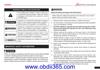
  • 1. LAUNCH PAD V User's Manual I Read all safety warnings and instructions. *Note: Failure to follow the warnings and instructions may result in electric shock, fire and/or serious injury. 1. Always perform automotive testing in a safe environment. 2. Do not connect or disconnect any test equipment while the ignition is on or the engine is running. 3. DO NOT attempt to operate the tool while driving the vehicle. Have second personal operate the tool. Any distraction may cause an accident. 4. Before starting the engine, put the gear lever in the Neutral position (for manual transmission) or in the Park (for automatic transmission) position to avoid injury. 5. NEVER smoke or allow a spark or flame in vicinity of battery or engine. Do not operate the tool in explosive atmospheres, such as in the presence of flammable liquids, gases, or heavy dust. 6. Keep a fire extinguisher suitable for gasoline/chemical/electrical fires nearby. 7. Wear an ANSI-approved eye shield when testing or repairing vehicles. 8. Put blocks in front of the drive wheels and never leave the vehicle unattended while testing. 9. Use extreme caution when working around the ignition coil, distributor cap, ignition wires and spark plugs. These components create hazardous voltage when the engine is running. 10. To avoid damaging the tool or generating false data, please make sure the vehicle battery is fully charged and the connection to the vehicle DLC (Data Link Connector) is clear and secure. WARNING SYMBOLS AND DEFINITIONS This safety alert symbol is used to alert you to potential injury hazards. Obey all safety messages that follow this symbol to avoid possible injury. Indicates an imminently hazardous situation which, if not avoided, could result in death or serious injury to the operator or to bystanders. Indicates a potentially hazardous situation which, if not avoided, could result in death or serious injury to the operator or to bystanders. Indicates a hazardous situation which, if not avoided, could result in minor or moderate injury to the operator or to bystanders. Addresses practices not related to personal injury. IMPORTANT SAFETY INFORMATION When an engine is operating, keep the service area well-ventilated or attach a building exhaust removal system to the engine exhaust system. Engines produce various poisonous compounds (hydrocarbon, carbon monoxide, nitrogen oxides, etc.) that cause slower reaction time and result in death or serious personal injury. www.obdii365.com
  • 2. II LAUNCH PAD V User's Manual 11. Automotive batteries contain sulfuric acid that is harmful to skin. In operation, direct contact with the automotive batteries should be avoided. Keep the ignition sources away from the battery at all times. 12. Keep the tool dry, clean, free from oil, water or grease. Use a mild detergent on a clean cloth to clear the outside of the equipment when necessary. 13. Keep clothing, hair, hands, tools, test equipment, etc. away from all moving or hot engine parts. 14. Store the tool and accessories in a locked area out of the reach of children. 15. Do not use the tool while standing in water. 16. Do not expose the tool or power adaptor to rain or wet conditions. Water entering the tool or power adaptor increases the risk of electric shock. Table of Contents 1 Introduction......................................................................................1 1.1 Product Profile................................................................................1 1.2 Features .........................................................................................1 1.3 Technical Specifications .................................................................2 2 Components & Controls .................................................................3 2.1 Display Tablet .................................................................................4 2.2 Docking Station (Optional)..............................................................5 2.3 VCI Device......................................................................................6 2.4 Accessory Checklist........................................................................7 3 Preparations.....................................................................................9 3.1 Charging the Tablet ........................................................................9 3.2 Power ON/OFF...............................................................................9 3.3 Locator & Navigation Buttons.......................................................10 3.4 Wi-Fi Setup...................................................................................10 4 Initial Use........................................................................................11 4.1 Getting Started .............................................................................11 4.2 Register & Download Diagnostic Software...................................11 4.3 Function Modules .........................................................................13 4.4 Vehicle Menu Layout ....................................................................14 4.5 Diagnostics toolbar.......................................................................14 5 Start Diagnostics...........................................................................16 5.1 Connections..................................................................................16 5.1.1 Preparation..........................................................................16 www.obdii365.com
  • 3. LAUNCH PAD V User's Manual III 5.1.2 DLC Location.......................................................................16 5.1.3 Vehicle Connection (For Passenger Vehicle Version) .........16 5.1.3 Vehicle Connection (For Commercial Vehicle Version/Diesel & Gasoline Version)......................................................................17 5.2 Communication Setup ..................................................................18 5.3 Start Diagnostics ..........................................................................18 5.3.1 Intelligent Diagnosis ............................................................18 5.3.2 Local Diagnosis ...................................................................20 5.4 Maintenance Reset.......................................................................31 5.4.1 Oil Reset Service.................................................................31 5.4.2 Electronic Parking Brake Reset...........................................32 5.4.3 Steering Angle Calibration...................................................32 5.4.4 ABS Bleeding.......................................................................32 5.4.5 Tire Pressure Monitor System Reset...................................32 5.4.6 Gear Learning......................................................................32 5.4.7 IMMO Service......................................................................33 5.4.8 Injector Coding ....................................................................33 5.4.9 Battery Maintenance System Reset ....................................33 5.4.10 Diesel Particulate Filter (DPF) Regeneration ....................33 5.4.11 Electronic Throttle Position Reset .....................................34 5.4.12 Gearbox Matching .............................................................34 5.4.13 AFS (Adaptive Front-lighting System) Reset ....................34 5.4.14 Sunroof Initialization ..........................................................34 5.4.15 Suspension Calibration .....................................................34 5.5 Remote Diagnosis ........................................................................35 5.5.1 Interface Layout...................................................................35 5.5.2 Add Friends .........................................................................35 5.5.3 Start Instant Messaging.......................................................36 5.5.4 Launch Remote Diagnosis (Device-To-Device)...................37 5.5.5 Launch Remote Diagnosis (Device-To-PC).........................38 5.6 Diagnostic History.........................................................................40 5.7 Software Update...........................................................................40 5.7.1 Update Diagnostic Software & APP.....................................40 5.7.2 Set Frequently Used software .............................................41 5.8 Store.............................................................................................41 5.9 ADAS............................................................................................42 5.10 Feedback....................................................................................43 6 User Info.........................................................................................44 6.1 My Report.....................................................................................44 6.2 VCI................................................................................................45 6.3 Immobilizer Programmer ..............................................................45 6.4 Activate VCI..................................................................................46 6.5 Fix connector firmware/system.....................................................46 6.6 My News.......................................................................................46 6.7 Data Stream Sample ....................................................................46 6.8 Vehicle Voltage.............................................................................46 6.9 My Order.......................................................................................46 6.10 Subscription Renewal Card........................................................46 6.11 Profile..........................................................................................46 6.12 Change Password ......................................................................47 6.13 Settings.......................................................................................47 6.13.1 Units ..................................................................................47 www.obdii365.com
  • 4. IV LAUNCH PAD V User's Manual 6.13.2 Shop Information ...............................................................47 6.13.3 Printer Set..........................................................................47 6.13.4 Clear Cache.......................................................................48 6.13.5 About .................................................................................48 6.13.6 Diagnostic Software Auto Update......................................48 6.13.7 Login/Exit from current account.........................................48 6.14 Diagnostic Software Clear..........................................................48 7 ToolBox ..........................................................................................49 7.1 Sensorbox & Multimeter (Optional) ..............................................49 7.1.1 Product summary ................................................................49 7.1.2 Components and Accessories.............................................50 7.1.3 Sensor Simulation ...............................................................51 7.1.4 Multimeter............................................................................55 7.2 Battery Tester (V1.0, Optional) .....................................................56 7.2.1 Product Summary................................................................56 7.2.2 Test Environment.................................................................57 7.2.3 Components and Accessories.............................................57 7.2.4 Connections & Operations...................................................58 7.2.5 Precautions on battery test .................................................60 7.2 Battery Detection (V2.0, Optional)................................................62 7.2.1 Product Summary................................................................62 7.2.2 Battery Health Test .............................................................64 7.2.3 Start System Test ...............................................................67 7.2.4 Charging Health Test..........................................................68 7.2.5 Reports...............................................................................70 7.3 Oscilloscope (Optional) ................................................................72 7.3.1 Introduction..........................................................................72 7.3.2 Structure & Accessories ......................................................72 7.3.3 Connection & Initial Use ......................................................75 7.3.4 Operations...........................................................................79 7.4 Ignition (Optional) .........................................................................85 7.4.1 Secondary-distributor ignition analysis................................85 7.4.2 Secondary-simultaneous ignition analysis...........................87 7.4.3 Secondary-direct ignition analysis.......................................88 7.4.4 Waveform analysis mode ....................................................89 7.5 Videoscope (Optional)..................................................................92 7.5.1 Introduction..........................................................................92 7.5.2 Components & controls .......................................................93 7.5.3 Technical Parameters..........................................................93 7.5.4 Connections & Operations...................................................94 8 Other Modules ...............................................................................95 8.1 Email.............................................................................................95 8.2 Browser ........................................................................................95 8.3 TeamViewer..................................................................................95 8.3.1 TeamViewer QuickSupport..................................................95 8.3.2 TeamViewer.........................................................................96 8.4 Wireless Upgrade.........................................................................96 8.5 Files..............................................................................................96 8.6 Gallery ..........................................................................................97 8.7 Recording Master .........................................................................97 Appendix - FAQ.................................................................................98 www.obdii365.com
  • 5. LAUNCH PAD V User's Manual 1 • Remote Diagnosis: This option aims to help repair shops or technicians launch instant messaging and remote diagnosis, making the repair job getting fixed faster. • Maintenance & Reset: All kinds of common maintenance and reset items including Oil lamp reset, DPF regeneration, ABS bleeding can be done. • One-click Update: Lets you update your diagnostic software online. • Diagnostic History: Provides a quick access to the tested vehicles and users can choose to view the test report or resume from previous diagnostic session, without the necessity of starting from scratch. • Pre- and Post- Repair Result Comparison: By comparing the pre- repair and post-repair report, you can clearly determine which vehicle issues have been fixed and which remained unsolved. • Diagnostic Feedback: Enables you to submit the vehicle issue to us for analysis and troubleshooting. • Toolbox: Scopebox, Sensorbox, Batterybox and Videoscope (sold separately) are available for extending the functions of the tablet. • Vehicle Coverage: Quick dial to view the vehicle models that the tablet covers. 2. WLAN connection is supported. 3. ADAS calibration: Optional. This function needs to be activated before normal use and only works with the LAUNCH-specific ADAS calibration tool. 4. Web browser: Users can make online search and visit any website. 5. File Manager: Lets you manage files or downloaded files stored in memory card efficiently. 6. Settings: To configure your personalized tablet. 1 Introduction 1.1 Product Profile X-431 PAD V is an evolutionary smart solution for specialized automotive diagnosis and maintenance. It inherits from LAUNCH’s advanced diagnosing technology and is characterized by covering a wide range of vehicles, featuring powerful functions, and providing precise test result. Through the wireless communication between VCI device and the tablet, it achieves full car model and full system vehicle trouble diagnosis, which include Reading DTCs, Clearing DTCs, Reading Data Stream, Actuation Test and Special Functions. Moreover, taking advantage of the mobile Internet, it also integrates One-click Update, Remote Diagnosis which helps to diagnose vehicle issues more efficiently, and greatly increase customer’s retention and boost shop revenue. This tool adopts a higher performance-price ratio display tablet, which comes loaded with two Wi-Fi modules, powerful 8-core 2GHz processor, 4G RAM, and a 10.1” sunlight readable capacitive touch screen with a resolution of 1920 x 1200 pixels. 1.2 Features 1. Diagnose: • Smart Diagnosis: This module allows you to use the VIN information of the currently identified vehicle to access its data (including vehicle information, historical diagnostic records) from the cloud server to perform quick test. • Local Diagnosis: To perform diagnosis by executing on-screen commands step by step. Diagnosis functions include: Read DTCs, Clear DTCs, Read Data Stream, Special Functions etc. www.obdii365.com
  • 6. 2 LAUNCH PAD V User's Manual B. VCI Device Item Description Working voltage DC 9V ~ 36V Memory 256MB ROM 8GB USB Type B x 1 Bluetooth BT2.1 & 4.2 WiFi 2.4G/5GHz dual frequency 1.3 Technical Specifications A. Display Tablet Item Description Operating system Android CPU 8-core processor, 2GHz Display 10.1 inch capacitive touch screen with 1920 x 1200 resolution Memory 4GB Hard disk 64GB Connectivity • Wi-Fi: 2.4G/5GHz dual frequency • Universal serial BUS Ports (1 x Type-C + 1 x Type-A) Cameras 8MP front-facing camera + 13MP rear- facing camera Size 320mm x 211mm x 46mm Operating Temperature -10℃ ~ 50℃(14 ~122℉) Storage Temperature -20℃ ~ 70℃(-4 ~158℉) www.obdii365.com
  • 7. LAUNCH PAD V User's Manual 3 2 Components & Controls There are three main components to the diagnostic system: • Display Tablet -- the central processor and monitor for the system (For details, please refer to Chapter 2.1.) Fig. 2-1 • Docking Station -- the platform for charging the tablet and extending functions (For details, please refer to Chapter 2.2.) Fig. 2-2 • VCI Device -- the device for accessing vehicle data (For details, please refer to Chapter 2.3.) Fig. 2-3 www.obdii365.com
  • 8. 4 LAUNCH PAD V User's Manual 2.1 Display Tablet Fig. 2-4 Top & front views Table 2-1 formulates ports and indicators of display tablet: No. Name & Descriptions 1 Memory Card Slot -- To store the memory card for storage expansion. 2 Type C Charging Port -- Reserved for charging the tablet. 3 Power/Screen Lock Button -- To turn the tablet on/off with long press, or lock the screen with short press. 4 Volume Buttons -- To adjust the volume. *Note: Press and hold [POWER] and [VOL -] key to capture the current screenshot. 5 Data I/O Port -- Reserved for add-on modules (such as Batterybox, Scopebox and Sensorbox), and other devices with similar port. 6 Microphone 7 Charging indicator -- It illuminates red while the tablet is charging. Once charging is finished, it will illuminate solid green. 8 10.1" Capacitive Touch Screen 9 Ambient Light Sensor 10 Front Camera www.obdii365.com
  • 9. LAUNCH PAD V User's Manual 5 2.2 Docking Station (Optional) Fig. 2-6 Docking Station Table 2-3 formulates ports of the docking station No. Name & Descriptions 1 Charging Slot -- To charge the tablet. 2 OBD16 Socket -- To store the VCI device to avoid loss. 3 DC 5V OUT Port -- (Reserved for charging other USB devices only.) 4 Type C Charging Port -- Use the power adaptor to supply power to the docking station through connection to AC outlet. 5 Power LED -- Illuminates solid green when it is powered up. Fig. 2-5 Rear view Table 2-2 formulates parts of display tablet (rear): No. Name & Descriptions 11 Rear Camera 12 Camera Flash 13 Audio Speaker 14 Charging Slot 15 Adjustable Kickstand - Flip out it to any angle and work comfortable at your desk, or hang it on automotive part. www.obdii365.com
  • 10. 6 LAUNCH PAD V User's Manual 2.3 VCI Device The VCI device works as a vehicle communication interface device, which is used to connect to the vehicle’s DLC (Data Link Connector) socket via OBD II extension cable to read the vehicle data and then send it to the tablet via Wi-Fi or data cable. Fig. 2-7 VCI device Table 2-4 formulates ports and indicators of VCI device: No. Name & Descriptions 1 OBD II-16 Diagnostic Connector -- Use the OBD II extension cable to connect VCI device to the vehicle’s OBDII DLC. 2 LED Indicators -- It is defined as follows: • Power: It illuminates solid red when the module is powered on. • Vehicle: While communicating with the vehicle, the indicator lights up and flashes. Otherwise, it will not illuminate. • BT: It illuminates when the VCI device is working in Bluetooth communication mode. • I/O: It lights up when the VCI device is connected to the tablet via data cable. • Wireless: It illuminates when the VCI device is working in Wi-Fi communication mode. 3 Reset Hole -- To reset the VCI device. 4 Data I/O port -- For connecting the VCI device to the tablet via data cable to perform vehicle diagnosis. 5 DC-IN power jack -- For connecting the power adaptor. www.obdii365.com
  • 11. LAUNCH PAD V User's Manual 7 2.4 Accessory Checklist Common accessories are same, but for different destinations, the accessories (such as diagnostic software, testing connectors) may vary. Please consult from the local agency or check the package list supplied with this tool together. Table 2-5 -- Common accessories and descriptions No. Name Qt. Picture 1 Display Tablet 1 2 VCI Device 1 (To connect to vehicle’s DLC.) 3 Docking Station 1 (Optional. To charge the tablet.) 4 Cigarette Lighter Cable 1 (To supply power to non-16pin dongle via vehicle’s cigarette lighter receptacle.) 5 Power Adaptor 1 (To charge the tablet.) 6 Cigarette Lighter Cable 1 (To provide power to the non-16 pin dongle through connection to the Cigarette Lighter receptacle.) 7 Battery Clamps Cable 1 (To provide power to the non-16 pin dongle through connection to the vehicle's battery.) www.obdii365.com
  • 12. 8 LAUNCH PAD V User's Manual 8 OBD II extension cable 1 (To connect the VCI device for extension purpose.) 9 OBD I Adaptor 1 (A adaptor cable for connecting non-16 pin dongle.) 10 Password Envelope 1 (A piece of paper bearing Product S/N and Activation Code, which is required for your registration.) 11 Non-16pin Connector Kit (Optional) www.obdii365.com
  • 13. LAUNCH PAD V User's Manual 9 3 Preparations 3.1 Charging the Tablet *Notes: • Only use the included power adaptor to recharge the tablet. Use of any other adaptor will damage the tool. We assume no responsibility for damage or loss resulting from using other similar adaptors other than the specified one. • Always charge on a non-flammable surface in a well-ventilated area. 1. To check the battery power level, press and hold the Power button about 3 seconds to turn on the tablet. 2. Power level is indicated as a percentage in the upper right corner of the screen. If the power level drops below 10% while the tablet is on, a "Connect Charger" notification will appear on the screen. A. Charging with the Included 5V Power Adaptor 1. Connect one end of the power adaptor to Type C charging port of the tablet, and the other end to the AC outlet. 2. The charging LED illuminates solid red and the charging sym- bol will apeear on the screen. 3. Once it illuminates solid green, it indicates that the battery is fully charged and the charging complete sym- bol replaces the charging symbol. Disconnect the pow- er adaptor from the AC outlet. B. Charging with the Docking Station 1. Locate the charging slot on the bottom of the tablet and docking station. 3. Insert one end of the included power cord to the charging port of the docking station, then the other end into the AC outlet. The charging LED illuminates solid red while charging and the charging symbol will apeear on the screen. 2. Align the charging slots, and then dock the tablet into the station to ensure that it is firmly seated on the docking station. 4. Once it illuminates solid green, it indicates that the battery is fully charged and the charging complete sym- bol replaces the charging symbol. Disconnect the dock- ing station from the AC outlet. 3.2 Power ON/OFF *Note: If it is the first time you use the tablet or the tablet keeps idle for a long time, it could fail to be turned on. It results from low battery. In this case, please recharge it for a while and try to turn it on. 1. Press and hold the POWER but- ton for about 3 seconds to turn on the tablet. The system starts initializing and then enters the Home screen. 2. To turn the tablet off, press and hold the POWER button until an option menu appears. Tap "Power Off". www.obdii365.com
  • 14. 10 LAUNCH PAD V User's Manual 3.3 Locator & Navigation Buttons 1 2 3 4 5 6 Fig. 3-1 On-screen keys and status bar are as follows: 1 Tap to visit the Launch’s official website. 2 Tap to capture the current screen and all captured screenshots are stored in the Screenshots folder. 3 : Shows whether the VCI device is properly connected or not. 4 Tap to display a list of applications that are currently running or recently used. To open an application, tap it. To remove an application, swipe it upwards. 5 Tap to navigate to the Android System’s home screen. 6 Tap to return to the previous screen or exit the application. 3.4 Wi-Fi Setup The tablet has dual built-in Wi-Fi communication modules. One is used to communicate with the tablet, and the other allows the tablet to get online. Once you’re online, you can register your tool, update diagnostic software & APK, browse the Internet, get apps and send email on your network. If the VCI device is successfully activated, the tablet will automatically connect to the VCI device. In this case it is not necessary for the user to manually configure it again. *Note: Once WLAN is set as ON, the tablet will consume more power. While it keeps unused, please set it off to save power. While WLAN is not in use, please turn it off to conserve battery power. Connect to a Wi-Fi Network 1. On the Home screen, tap Tablet Settings > WLAN. 2. Move the Wi-Fi switch to ON, the tablet starts searching for available wireless LANs. 3. Select the desired Wi-Fi net- work from the list. If the cho- sen network is open, you can connect directly. A password may be required for secured networks. Disconnect from a Wi-Fi Network 1. On the Home screen, tap Tablet Settings > WLAN. 2. Tap the network with a “Con- nected” status, then tap “For- get”. www.obdii365.com
  • 15. LAUNCH PAD V User's Manual 11 4 Initial Use 4.1 Getting Started For new users, please follow the operation chart shown in Fig. 4-1 to get familiar with and start using this tool. Tap “ Diagnose” Select vehicle Select test system Select test function Select diagnostic software version Tap “Login” to register Is VCI connector activated ? No Download/Update diagnostic software Yes …… (Refer to Chapter 4.2) Register & Activate OK Fig. 4-1 *Note: Before registering, please make sure that the tablet has a strong and stable Wi-Fi signal. 4.2 Register & Download Diagnostic Software On the home screen, tap the application icon to launch it, and then tap “Login” to enter the login interface of diagnosis software. Fig. 4-2 (If you are a new user, follow A to proceed.) (If you have registered to be a member, go to B to login the system directly.) (In case you forgot password, refer to C to reset a new password.) A. If you are a new user, tap “New Registration” to enter registration page. See Fig. 4-3. Fig. 4-3 In Fig. 4-3, fill in the information in each field (Items with * must be filled). After inputting, tap “Register”, a screen similar to the following www.obdii365.com
  • 16. 12 LAUNCH PAD V User's Manual will appear: Fig. 4-4 In Fig. 4-4, input the Serial Number and Activation Code, which can be found in the password envelope. Fig. 4-5 *Note: To exit and activate it later, tap “Skip”. In this case, you can activate your connector by tapping “Activate VCI” under the “User Info” tab. Tap “Activate” to finish your registration. See Fig. 4-6. Fig. 4-6 To download the diagnostic software, tap “Yes” to enter the download page. Tap “No” to download and install it later. On download page, tap “Update” to start downloading. To pause downloading, tap “Stop”. To resume it, tap “Continue”. Once download is complete, the system will install the software package automatically. *Notes: • In process of download, please make sure the tablet has a strong Wi-Fi signal. It may take several minutes to finish it, please be patient to wait. • To use the AutoDetect (VINScan) function, you have to download the corresponding diagnostic software and AutoSearch file. B. If you have registered to be a member, input your name and password, and then tap the “Login” button to enter the main menu screen directly. *Note: The tablet has an auto-save function. Once the username and password are correctly entered, the system will automatically store it. Next time you login the system, you will not be asked to input the account manually. C. If you forgot the password, tap “Retrieve password” and then follow on-screen instructions to set a new password. www.obdii365.com
  • 17. LAUNCH PAD V User's Manual 13 4.3 Function Modules Fig. 4-7 It mainly includes the following items: Intelligent Diagnose This module allows you to obtain vehicle data from the cloud server to perform quick test via reading VIN, which provides a perfect solution to various defects resulting from step-by- step menu selection. In addition, user can also check the historical repair records online through this module. Local Diagnose To diagnose a vehicle manually. ADAS This function enables users to perform ADAS (Advanced Driver Assistance System) calibration operations. The ADAS calibration software is disabled by default. Before using this function, users must activate the ADAS function using the ADAS Activation Card. Software Update To update vehicle diagnostic software and APK. Remote Diagnose This option aims to help repair shops or technicians launch instant messaging and remote diagnosis, making the repair job getting fixed faster. Reset To perform all kinds of common repair & maintenance items, including electronic throttle position reset, ABS bleeding, DPF regeneration, oil lamp reset etc. *Note: This module only applies to Passenger Vehicle /Gasoline & Diesel Version. Feedback To feed back the recent 20 diagnostic logs to us for issue analysis. Maintenance Abundant maintenance data are available, which helps repair professionals diagnose and repair vehicles efficiently, accurately and profitably. Toolbox Includes Camera, Browser, Oscilloscope, Ignition, Sensor, Multimeter, Battery etc. User Info To manage VCI, diagnostic reports & records, change password, configure Wi-Fi printer, sample data and logout / login etc. Vehicle Coverage To check the vehicle models supported on the tablet. Tablet Setting Configures the system setting of the tablet. www.obdii365.com
  • 18. 14 LAUNCH PAD V User's Manual 1 VINScan button: Tap it to scan the Vehicle Identification Number (VIN) code of your vehicle. OBD VIN and INPUT VIN are included. This function does not apply to the commercial vehicles. *Note: Before using this function, the corresponding diagnostic software and Auto search file need to be downloaded on your tool first while downloading the diagnostic software. 2 All Tab: Displays all the vehicle makes in the vehicle menu. 3 Common Tab: Displays all frequently-used vehicle makes. 4 Regional buttons: Tap different buttons to switch to corresponding vehicles. 5 HD: If you have purchased a Gasoline & Diesel Version and activated it, this tab will appear. 6 History Button: Generally once a vehicle diagnosis is performed, the tablet will record the every details of diagnostic process. This function provides a quick access to the previously tested vehicles. Testing can be resumed from the previous operation without starting from scratch. 7 Store: Allows you to renew the subscription of diagnostic software and check the order status. 8 Search bar: Input the desired vehicle model to quickly locate it. 4.5 Diagnostics toolbar The diagnostics toolbar contains a number of buttons that allow you to print the displayed data or make other controls. It is displayed on Other Modules Includes TeamViewer, Email, Browser, Wireless Upgrade and FAQ etc. 4.4 Vehicle Menu Layout After downloading the diagnostic software, you can go to “Local Diagnose” to check if all software are completely downloaded and installed. Tap “Local Diagnosis”, a screen similar to the following figure appears: 1 2 3 4 5 6 7 8 Fig. 4-8 www.obdii365.com
  • 19. LAUNCH PAD V User's Manual 15 the upper right corner of the screen and goes through the whole diagnostic session. The table below provides a brief description for the operations of the diagnostics toolbar buttons: Home Tap to navigate to the home screen. Print Tap to print the current screen. To perform printing, you need to purchase an extra Wi-Fi printer separately. Exit Session Tap to exit the current diagnostic session. www.obdii365.com
  • 20. 16 LAUNCH PAD V User's Manual 5 Start Diagnostics 5.1 Connections 5.1.1 Preparation Normal testing conditions • Turn on the vehicle power supply. • Vehicle battery voltage range should be 9-18V or 11-36V and working voltage of the tablet is 5V. • Throttle should be closed at its close position. • Ignition timing and idle speed should be within specified range; water and transmission oil temperature are within normal working range (water temperature is 90-110℃ and transmission oil temperature is 50-80℃). Select testing connectors/adaptor cables If the tablet is testing vehicles equipped with universal OBD II 16 PIN diagnostic socket, please use the included VCI device. (For vehicles with non-OBD II 16 PIN diagnostic socket, a non-16 PIN dongle is required.) 5.1.2 DLC Location For Passenger Vehicles, the DLC (Data Link Connector or Diagnostic Link Connector) is the standardized 16-cavity connector where diagnostic code readers interface with the vehicle’s on-board computer. The DLC is usually located 12 inches from the center of the instrument panel (dash), under or around the driver’s side for most vehicles. If Data Link Connector is not located under dashboard, a label should be there telling location. For some Asian and European vehicles, the DLC is located behind the ashtray and the ashtray must be removed to access the connector. If the DLC cannot be found, refer to the vehicle’s service manual for the location. Fig. 5-1 For Commercial Vehicles, the DLC is located in the driver’s cab. 5.1.3 Vehicle Connection (For Passenger Vehicle Version) The method used to connect the VCI device to a vehicle’s DLC depends on the vehicle’s configuration as follows: • A vehicle equipped with an OBD II management system supplies both communication and 12V power through a standardized DLC. • A vehicle not equipped with an OBD II management system supplies communication through a DLC connection, and in some cases supplies 12V power through the cigarette lighter receptacle or a connection to the vehicle battery. Follow the steps mentioned below to connect OBD II vehicle: 1. Locate vehicle’s DLC socket. 2. Use the OBD II extension cable to connect the VCI device to the vehicle’s DLC socket. 3. Choose one of the two ways to obtain power from: A. Power adaptor: Connect one end of the included power adaptor to Power interface of the tablet, and the other end to AC outlet. B. Internal battery pack: For details on how to recharge the tablet, see “Chapter 3.1 Charging the tablet”. www.obdii365.com
  • 21. LAUNCH PAD V User's Manual 17 For non-OBDII vehicle, proceed as follows: 1. Locate vehicle’s DLC socket. 2. Select the corresponding non-16pin dongle. 3. Plug the non-16pin end of the non-16pin adaptor into the DLC socket, then connect the other end to the OBD I adaptor, and then tighten the captive screws. 4. Connect the other end of the adaptor to the included VCI device. 5. To supply power to OBD I adaptor from: A. Cigaretter Lighter: Connect one end of the cigarette lighter cable to vehicle’s cigarette lighter receptacle, and the other end to the DC-IN jack of the VCI device. VCI device Cigarette lighter OBD I adaptor Non-16pin adaptor To vehicle's DLC To Cigarette lighter receptacle Fig. 5-2 B. Battery Clamps Cable: Connect one end of the battery clamps cable to vehicle’s battery, and the other end to the power jack of OBDI adaptor. VCI device Battery clamps cable OBD I adaptor Non-16pin adaptor To vehicle's DLC To vehicle's battery Fig. 5-3 5.1.3 Vehicle Connection (For Commercial Vehicle Version/ Diesel & Gasoline Version) The method used to connect the VCI device to a vehicle’s DLC depends on the vehicle’s configuration as follows: For OBD II vehicle, directly plug the VCI device into the vehicle’s DLC (OBD II extension cable is recommended). For non-OBD II vehicle, follow either of the ways to proceed: 1. Locate vehicle’s DLC socket. 2. Select the corresponding non-16pin dongle. 3. Plug the non-16pin end of the non-16pin adaptor into the DLC socket, then connect the other end to the OBD II extension cable. 4. Connect the other end of the adaptor to the included VCI device. 5. To supply power to OBD I adaptor from: A. Cigaretter Lighter: Connect one end of the cigarette lighter cable to vehicle’s cigarette lighter receptacle, and the other end to the DC-IN jack of the VCI device. www.obdii365.com
  • 22. 18 LAUNCH PAD V User's Manual VCI device Cigarette lighter OBD II extension cable Non-16pin adaptor To vehicle's DLC To Cigarette lighter receptacle Fig. 5-4 B. Battery clamps cable: Connect one end of the battery clamps cable to vehicle’s battery (Red to + & Black to - ), and the other end to the DC-IN jack of the VCI device. VCI device Battery clamps cable OBD II extension cable Non-16pin adaptor To vehicle's DLC To vehicle's battery Fig. 5-5 5.2 Communication Setup There are two kinds of ways available for the tablet to communicate with the VCI device: Wi-Fi and USB cable. After the sign-up is successfully completed, the Wi-Fi communication between the tablet and the VCI device is automatically done and user has no need to configure it again. The USB cable connection is a simple & quick way to establish communication between the tablet and the VCI module. After properly connecting the USB cable from the tablet to the VCI, the VCI navigation button at the bottom of the screen becomes highlighted indicating the USB connection is successful. *Note: The USB connection provides the most stable and fastest communication. When all communication methods are applied at the same time, the tablet will use the USB communication as the default priority. 5.3 Start Diagnostics 5.3.1 Intelligent Diagnosis Through simple Wi-Fi communication between the tablet and VCI, you can easily get the VIN (Vehicle Identification Number) information of the currently identified vehicle. Once the VIN is successfully identified, the system will retrieve it from the remote server and then guide you to vehicle information page without the necessity of step-by-step manual menu selection. The vehicle information page lists all historical diagnostic records of the vehicle, which lets the technician have a total command of the vehicle faults. In addition, a quick dial to local diagnosis and diagnostic function are also available on this page for reducing the roundabout time and increasing productivity. *Notes: • Before using this function, please make sure the VCI is properly connected to the vehicle’s DLC. For detailed connection, see Chapter 5.1.3 “Vehicle Connection”. • A stable network connection is required for this function. Follow the steps below to proceed. 1. Tap “Intelligent Diagnose” on the Job Menu to enter Fig. 5-6. www.obdii365.com
  • 23. LAUNCH PAD V User's Manual 19 Fig. 5-6 2. After pairing is complete, the handset starts reading the vehicle VIN. A. If the VIN can be found from the remote server database, a screen similar to the following figure displays: Fig. 5-7 • Tap “Diagnostic” to start a new diagnostic session. • Tap “Scan History” to view its historical repair record. If there are records available, it will be listed on the screen in sequence of date. If no records exist, the screen will show “No Record”. Fig. 5-8 • Tap “View record” to view the details of the current diagnostic report. • To perform other functions, tap “Quick access” to directly go to the function selection screen. Choose the desired one to start a new diagnostic session. B. If the handset failed to access the VIN information, the screen will display as below: Fig. 5-9 www.obdii365.com
  • 24. 20 LAUNCH PAD V User's Manual In this mode, you need to input the VIN manually or tap to scan it. 1) Tap to launch the VIN recognition module. Fig. 5-10 Place the VIN inside the viewfinder rectangle to scan it. The most recognizable location for this number is in the top left corner on the vehicle’s dashboard. Other locations include the driver’s door or post, and the firewall under the hood. • To switch the display orientation, tap . • To turn the flash on, tap . • If you have scanned the VIN of the vehicle, tap to choose it from the record list. • In case the handset failed to detect it, tap to enter it manually. • Tap to switch the camera to barcode pattern recognition mode. • indicates the camera is in character pattern recognition mode (default mode). After scanning, the screen automatically displays the result. Fig. 5-11 • If the VIN scanned is incorrect, tap the result field to modify it and then tap “OK”. If the VIN exists on the remote server, the system will enter the vehicle information screen. See Fig. 5-8. • To scan it again, tap “REPEAT”. 2) Input the VIN, and tap “OK”, the system will automatically identify the vehicle model and directly navigate to the vehicle information page. *Note: In general, vehicle identification numbers are standardized - all contain 17 characters. VIN characters may be capital letters A through Z and numbers 1 through 0; however, the letters I, O and Q are never used in order to avoid mistakes of misreading. No signs or spaces are allowed in the VIN. 5.3.2 Local Diagnosis Tap “Local Diagnose” to enter the vehicle selection page. 2 approaches are provided for you to access the vehicle diagnostic software. Choose any one of the following ways: 1. VINSCAN This function enables you to access it more quickly. www.obdii365.com
  • 25. LAUNCH PAD V User's Manual 21 • To switch the display orientation, tap . • To turn the flash on, tap . • If you have scanned the VIN of the vehicle, tap to choose it from the record list. • In case the handset failed to detect it, tap to enter it manually. • Tap to switch the camera to barcode pattern recognition mode. • indicates the camera is in character pattern recognition mode (default mode). Once the test vehicle is successfully identified, the tablet will jump to the function selection page directly. Tap the desired option to perform the corresponding function. *Note: Before using this function, the corresponding diagnostic software and Auto search file need to be downloaded on your tool first while downloading the diagnostic software. B. INPUT VIN: In this mode, you need to input the VIN manually. In general, vehicle identification numbers are standardized - all contain 17 characters. VIN characters may be capital letters A through Z and numbers 1 through 0; however, the letters I, O and Q are never used in order to avoid mistakes of misreading. No signs or spaces are allowed in the VIN. Tap “INPUT VIN” and a screen similar to Fig. 5-14 will appear: Fig. 5-14 In this case, automatic scan (OBD VIN) and manual input (INPUT VIN) are available. Tap “VINScan”, the screen displays as follows: Fig. 5-12 A. Camera Scan: In this mode, the VCI device should be plugged into the vehicle’s DLC. Tap “Camera Scan”, a screen similar to the following appears: Fig. 5-13 Place the VIN inside the viewfinder rectangle to scan it. The most recognizable location for this number is in the top left corner on the vehicle’s dashboard. Other locations include the driver’s door or post, and the firewall under the hood. www.obdii365.com
  • 26. 22 LAUNCH PAD V User's Manual Input the VIN, and tap “Confirm”, the system will automatically identify the vehicle model and directly navigate to the function selection page. 2. Manual Selection Tap a corresponding diagnostic software logo, and then follow the on- screen instruction to access the diagnostic software. Take Demo as an example to demonstrate how to diagnose a vehicle. 1). Select diagnostic software version: Tap the “DEMO” to go to Step 2. (*Note: If more than one version is available on this tablet, it will be listed on the screen.) Fig. 5-15 On-screen Buttons: Vehicle Coverage: Tap to view the vehicle models that the current diagnostic software covers. What’s new: Tap to view the optimized items and enhancements. Introduction: Tap to check the software function list. Note: Tap to read some precautions on using the current diagnostic software. OK: Tap it to go to next step. 2). Select test item: Select the desired test item to proceed. Fig. 5-16 5.3.2.1 Health Report (Quick Test) This function varies from vehicle to vehicle. It enables you to quickly access all the electronic control units of the vehicle and generate a detailed report about vehicle health. Tap “Health Report”, the system starts scanning the ECUs. Once the scanning is complete, a screen similar to the following appears: Fig. 5-17 In Fig. 5-17, the tested system with fault code appears in red and the system with OK displays in white (normally). www.obdii365.com
  • 27. LAUNCH PAD V User's Manual 23 *Note: Diagnostic Trouble Codes or Fault Codes can be used to identify which engine systems or components that are malfunctioning. Never replace a part based only on the DTC definition. Retrieving and using DTCs for troubleshooting vehicle operation is only one part of an overall diagnostic strategy. Follow testing procedures (in vehicle’s service manual), instructions and flowcharts to confirm the locations of the problem. On-screen Buttons: : Tap to display the details of DTCs existing in the current system. Tap to hide it. Highlight certain DTC item, and tap to open the browser to retrieve it in Google engine. Fig. 5-18 Enter: Tap to select other test functions. Fig. 5-19 Report: Tap to save the diagnostic result as a report. Fig. 5-20 www.obdii365.com
  • 28. 24 LAUNCH PAD V User's Manual *Note: Diagnostic report is classified into three categories: Pre-Repair report, Post-Repair report and Diagnostic Scan. No matter which type you saved the report as, the report type will be appended as a tag on the upper right corner of the diagnostic report for easier identification. Tap to select the report type from the option list and input the required information, and then tap “OK”. *Note: To facilitate the comparison of the pre-repair and post-repair reports and get accurate test result, please make sure you saved the right type of the diagnostic report. To save the report as a common diagnostic report, select “Diagnostic Scan”. Fig. 5-21 Enter the technician and customer name and then tap “OK” to confirm and navigate to the report details page. *Note: For workshop information, tap “Change” to revise it. Alternatively you can also set it in “User Info” -> “Settings” -> “Print Information”. Once you configured the information, it will be automatically generated every time you saved the diagnostic report. All vehicle and workshop information will be appended as tags on the diagnostic report. To ignore the workshop information, tap “Skip” to go to the report details page. On the report details page, tap “Save” to save it. All diagnostic reports can be accessed from “User Info” -> “My Reports” -> “Health Report”. Help: Tap to view the help information of the selected DTC item. Compare Results: Tap to select the pre-repair report to compare. By comparison of the pre- and post- repair reports, you can easily identify which DTCs are cleared and which remain unfixed. www.obdii365.com
  • 29. LAUNCH PAD V User's Manual 25 The DTC status of post-repair The DTC status of pre-repair Fig. 5-22 *Note: Before performing this function, please make sure that: • You have saved a pre-repair report of the currently tested vehicle, and • You have already made some repairs and service and cleared the DTCs after the pre-repair reported is generated. Otherwise, no differences exist between the pre- and post- repair reports. Clear DTC: Tap to clear the existing diagnostic trouble codes. *Note: Clearing DTCs does not fix the problem(s) that caused the code(s) to be set. If proper repairs to correct the problem that caused the code(s) to be set are not made, the code(s) will appear again and the check engine light will illuminate as soon as the problem that cause the DTC to set manifests itself. 5.3.2.2 System Scan This option allows you to quickly scan which systems are installed on the vehicle. In Fig. 5-16, tap “System Scan”, the system starts scanning the systems. Once the scanning is complete, the screen will display the result. Fig. 5-23 Tap the desired system to advance to the test function selection page. For detailed operations on test function, please refer to Chapter 5.3.2.3. 5.3.2.3 System Selection This option allows you manually select the test system and function step by step. In Fig. 5-16, tap “System Selection”, the screen displays as follows: www.obdii365.com
  • 30. 26 LAUNCH PAD V User's Manual Fig. 5-24 Swipe the screen from the bottom to view the vehicle system on the next page. Tap the desired system (take “ECM” for example) to jump to the test function page. Fig. 5-25 *Note: Different vehicle has different diagnostic menus. A. Version Information This function is used to read the version information of system mode, vehicle VIN, software and ECU. In Fig. 5-25, tap “Version Information”, the screen displays as follows: Fig. 5-26 Tap “OK” to confirm and exit. B. Read Fault Code This function displays the detailed information of DTC records retrieved from the vehicle’s control system. In Fig. 5-25, tap “Read Fault Code”, the screen will display the diagnostic result. Fig. 5-27 www.obdii365.com
  • 31. LAUNCH PAD V User's Manual 27 *Note: Retrieving and using DTCs for troubleshooting vehicle operation is only one part of an overall diagnostic strategy. Never replace a part based only on the DTC definition. Each DTC has a set of testing procedures, instructions and flow charts that must be followed to confirm the location of the problem. This information can be found in the vehicle’s service manual. On-screen Buttons: Freeze Frame: When an emission-related fault occurs, certain vehicle conditions are recorded by the on-board computer. This information is referred to as freeze frame data. Freeze frame data includes a snapshot of critical parameter values at the time the DTC is set. Help: Tap to view the help information. Code Search: Tap it to search for more information about the current DTC online. Report: To save the current data in text format. All diagnostic reports can be accessed from “User Info” -> “My Reports” -> “Diagnostic Report”. C. Clear Fault Code After reading the retrieved codes from the vehicle and certain repairs have been carried out, you can use this function to erase the codes from the vehicle. Before performing this function, please be sure the vehicle’s ignition key is in the ON position with the engine off. Clearing DTCs does not fix the problem(s) that caused the code(s) to be set. If proper repairs to correct the problem that caused the code(s) to be set are not made, the code(s) will appear again and the check engine light will illuminate as soon as the problem that cause the DTC to set manifests itself. In Fig. 5-25, tap “Clear Fault Code”, a confirmation dialog box pops up on the screen. Tap “Yes” and the system will automatically delete the currently existing trouble code. *Note: After clearing, you should retrieve trouble codes once more or turn ignition on and retrieve codes again. If there are still some trouble codes in the system, please troubleshoot the code using a factory diagnosis guide, then clear the code and recheck. D. Read Data Stream This option lets you view and capture (record) real-time Live Data. This data including current operating status for parameters and/or sensor information can provide insight on overall vehicle performance. It can also be used to guide vehicle repair. *Note: If you must drive the vehicle in order to perform a troubleshooting procedure, always have a second person help you. Trying to drive and operate the diagnostic tool at the same time is dangerous, and could cause a serious traffic accident. In Fig. 5-25, tap “Read Data Stream”, the system will display data stream items. Fig. 5-28 www.obdii365.com
  • 32. 28 LAUNCH PAD V User's Manual On-screen Buttons: Select All: Tap it to select all items of the current page. To select certain data stream item, just check the box before the item name. Unselect: Tap it to deselect all data stream items. OK: Tap it to confirm and jump to the next step. After selecting the desired items, tap “OK” to enter the data stream reading page. Fig. 5-29 *Notes: 1. If the value of the data stream item is out of the range of the standard (reference) value, the whole line will display in red. If it complies with the reference value, it displays in blue (normal mode). 2. The indicator 1/X shown on the bottom of the screen stands for the current page/total page number. Swipe the screen from the right/left to advance/return to the next/previous page. There are 3 types of display modes available for data viewing, allowing you to view various types of parameters in the most suitable way. • Value – this is the default mode which displays the parameters in texts and shows in list format. • Graph – displays the parameters in waveform graphs. • Combine – this option is mostly used in graph merge status for data comparison. In this case, different items are marked in different colors. On-screen Buttons: : Tap it to view the waveform graph of the current data stream item. Fig. 5-30 • Min/Max: Tap to define the maximum/minimum value. Once the value goes beyond the specified value, the system will alarm. *Note: The real time (Live Data) vehicle operating information (values/status) that the on-board computer supplies to the tool for each sensor, actuator, switch, etc. is called Parameter Identification Data (PID). Graph: Tap it to view the waveform. www.obdii365.com
  • 33. LAUNCH PAD V User's Manual 29 Fig. 5-31 • Combine: This option is mostly used in graph merge status for data comparison. Fig. 5-32 • Value: Tap to display the parameters in texts. • Customize: Tap , a pull-down list of the data stream items appears on the screen. Select (Maximum 8 data stream items can be selected)/deselect the desired items and then screen will display/remove the waveforms corresponding to these items immediately. Fig. 5-33 Select Sample DS: Tap it to select the sample DS file, the values you customized and saved in process of DS sampling will be imported into the “Standard Range”(See below) column for your comparison. *Note: Before executing this function, you have to sample the values of data stream items and save it as an sample DS file. www.obdii365.com
  • 34. 30 LAUNCH PAD V User's Manual Fig. 5-34 Report: To save the current data as a diagnostic report. All diagnostic reports can be accessed from “User Info” -> “My Reports” -> “Health Report”. Record: Tap to start recording diagnostic data. Recorded live data can serve as valuable information to help you in troubleshooting of vehicle problems. All diagnostic records can be replayed from “User Info” -> “My Reports” -> “Recorded Data”. *Note: The saved file follows the naming rule: It begins with vehicle type, and then the product S/N and ends with record starting time (To differentiate between files, please configure the accurate system time). Help: Tap to view the help information. Sample DS: This item enables you to customize the standard range of live data stream items and save it as DS sample file. Each time you run the data stream items, you can call out the corresponding sample data to overwrite the current standard range. Tap it to start recording the sample data (*Only data stream items with measurement units will be recorded), and the screen displays as below: Fig. 5-35 Once recording is complete, tap to stop it and navigate to the data revision screen. Fig. 5-36 Tap the Min./Max. value to change it. After modifying all desired items, tap “Save” to save it as a sample DS file. All DS files are stored under the “Data Stream Sample” file in “User Info.”. E. Actuation Test This option is used to access vehicle-specific subsystem and component tests. Available test vary by vehicle manufacturer, year, and model. During the actuation test, the tablet outputs commands to the ECU in order to drive the actuators, and then determines the integrity of the system or parts by reading the ECU data, or by monitoring the operation of the actuators, such as switching a injector between two operating states. In Fig. 5-25, tap “Actuation Test”, the system will display as follows: www.obdii365.com
  • 35. LAUNCH PAD V User's Manual 31 Fig. 5-37 Simply follow the on-screen instructions and make appropriate selections to complete the test. Each time when an operation is successfully executed, “Completed” displays. 5.4 Maintenance Reset In addition to amazing & powerful diagnostic function, the tablet also features various service functions. The most commonly performed service functions contain: • Oil Reset Service • Electronic Parking Brake Reset • Steering Angle Calibration • ABS Bleeding • TPMS (Tire Pressure Monitor System) Reset • Gear Learning • IMMO Service • Injector Coding • Battery Maintenance System • Diesel Particulate Filter (DPF) Regeneration • Electronic Throttle Position Reset • Gearbox Matching • AFS (Adaptive Front-lighting System) Reset • Sunroof Initialization • Suspension Calibration There are two methods to reset service lamp: Manual reset or Auto reset. Auto reset follows the principle of sending command from the tool to vehicle’s ECU to do resetting. While using manual reset, users just follow the on-screen instructions to select appropriate execution options, enter correct data or values, and perform necessary actions, the system will guide you through the complete performance for various service operations. Select “Reset” Select the desired reset item (e.g. oil lamp reset etc.) Select the car brand Select the service mode (The available mode varies from vehicle to vehicle) Follow the instructions on the screen to operate Figure 5-3 5.4.1 Oil Reset Service This function allows you to perform reset for the engine oil life system, which calculates an optimal oil life change interval depending on the www.obdii365.com
  • 36. 32 LAUNCH PAD V User's Manual vehicle driving conditions and climate. This function can be performed in the following cases: 1. If the service lamp is on, you must provide service for the car. After service, you need to reset the driving mileage or driving time so that the service lamp turns off and the system enables the new service cycle. 2. After changing engine oil or electric appliances that monitor oil life, you need to reset the service lamp. 5.4.2 Electronic Parking Brake Reset 1. If the brake pad wears the brake pad sense line, the brake pad sense line sends a signal sense line to the on-board computer to replace the brake pad. After replacing the brake pad, you must reset the brake pad. Otherwise, the car alarms. 2. Reset must be performed in the following cases: a) The brake pad and brake pad wear sensor are replaced. b) The brake pad indicator lamp is on. c) The brake pad sensor circuit is short, which is recovered. d) The servo motor is replaced. 5.4.3 Steering Angle Calibration To reset the steering angle, first find the relative zero point position for the car to drive in straight line. Taking this position as reference, the ECU can calculate the accurate angle for left and right steering. After replacing the steering angle position sensor, replacing steering mechanical parts (such as steering gearbox, steering column, end tie rod, steering knuckle), performing four-wheel alignment, or recovering car body, you must reset the steering angle. 5.4.4 ABS Bleeding This function allows you to perform various bi-directional tests to check the operating conditions of Anti-lock Braking System (ABS). 1. When the ABS contains air, the ABS bleeding function must be performed to bleed the brake system to restore ABS brake sensitivity. 2. If the ABS computer, ABS pump, brake master cylinder, brake cylinder, brake line, or brake fluid is replaced, the ABS bleeding function must be performed to bleed the ABS. 5.4.5 Tire Pressure Monitor System Reset This function allows you to quickly look up the tire sensor IDs from the vehicle’s ECU, as well as to perform TPMS replacement and sensor test. 1. After the tire pressure MIL turns on and maintenance is performed, the tire pressure resetting function must be performed to reset tire pressure and turn off the tire pressure MIL. 2. Tire pressure resetting must be performed after maintenance is performed in the following cases: tire pressure is too low, tire leaks, tire pressure monitoring device is replaced or installed, tire is replaced, tire pressure sensor is damaged, and tire is replaced for the car with tire pressure monitoring function. 5.4.6 Gear Learning The crankshaft position sensor learns crankshaft tooth machining tolerance and saves to the computer to more accurately diagnose engine misfires. If tooth learning is not performed for a car equipped with Delphi engine, the MIL turns on after the engine is started. The diagnostic device detects the DTC P1336 ‘tooth not learned’. In this case, you must use the diagnostic device to perform tooth learning for the car. After tooth learning is successful, the MIL turns off. www.obdii365.com
  • 37. LAUNCH PAD V User's Manual 33 After the engine ECU, crankshaft position sensor, or crankshaft flywheel is replaced, or the DTC ‘tooth not learned’ is present, tooth learning must be performed. 5.4.7 IMMO Service An immobilizer is an anti-theft mechanism that prevents a vehicle’s engine from starting unless the correct ignition key or other device is present. Most new vehicles have an immobilizer as standard equipment. An important advantage of this system is that it doesn’t require the car owner to activate it since it operates automatically. An immobilizer is considered as providing much more effective anti-theft protection than an audible alarm alone. As an anti-theft device, an immobilizer disables one of the systems needed to start a car’s engine, usually the ignition or the fuel supply. This is accomplished by radio frequency identification between a transponder in the ignition key and a device called a radio frequency reader in the steering column. When the key is placed in the ignition, the transponder sends a signal with a unique identification code to the reader, which relays it to a receiver in the vehicle’s computer control module. If the code is correct, the computer allows the fuel supply and ignition systems to operate and start the car. If the code is incorrect or absent, the computer disables the system, and the car will be unable to start until the correct key is placed in the ignition. To prevent the car being used by unauthorized keys, the anti-theft key matching function must be performed so that the immobilizer control system on the car identifies and authorizes remote control keys to normally use the car. When the ignition switch key, ignition switch, combined instrument panel, ECU, BCM, or remote control battery is replaced, anti-theft key matching must be performed. 5.4.8 Injector Coding Write injector actual code or rewrite code in the ECU to the injector code of the corresponding cylinder so as to more accurately control or correct cylinder injection quantity. After the ECU or injector is replaced, injector code of each cylinder must be confirmed or re-coded so that the cylinder can better identify injectors to accurately control fuel injection. 5.4.9 Battery Maintenance System Reset This function enables you to perform a resetting operation on the monitoring unit of vehicle battery, in which the original low battery fault information will be cleared and battery matching will be done. Battery matching must be performed in the following cases: a) Main battery is replaced. Battery matching must be performed to clear original low battery information and prevent the related control module from detecting false information. If the related control module detects false information, it will invalidate some electric auxiliary functions, such as automatic start & stop function, sunroof without one-key trigger function, power window without automatic function. b) Battery monitoring sensor. Battery matching is performed to re- match the control module and motoring sensor to detect battery power usage more accurately, which can avoid an error message displaying on the instrument panel. 5.4.10 Diesel Particulate Filter (DPF) Regeneration DPF regeneration is used to clear PM (Particulate Matter) from the DPF filter through continuous combustion oxidation mode (such as high temperature heating combustion, fuel additive or catalyst reduce PM ignition combustion) to stabilize the filter performance. www.obdii365.com
  • 38. 34 LAUNCH PAD V User's Manual DPF regeneration may be performed in the following cases: a) The exhaust back pressure sensor is replaced. b) The PM trap is removed or replaced. c) The fuel additive nozzle is removed or replaced. d) The catalytic oxidizer is removed or replaced. e) The DPF regeneration MIL is on and maintenance is performed. f) The DPF regeneration control module is replaced. 5.4.11 Electronic Throttle Position Reset This function enables you to make initial settings to throttle actuators and returns the “learned” values stored on ECU to the default state. Doing so can accurately control the actions of regulating throttle (or idle engine) to adjust the amount of air intake. 5.4.12 Gearbox Matching 1. This function can complete the gearbox self-learning to improve gear shifting quality. 2. When the gearbox is disassembled or repaired (after some of the car battery is powered off), it will lead to shift delay or impact problem. In this case, this function needs to be done so that the gearbox can automatically compensate according to the driving conditions so as to achieve more comfortable and better shift quality. 5.4.13 AFS (Adaptive Front-lighting System) Reset This feature is used to initialize the adaptive headlamp system. According to the ambient light intensity, the adaptive headlamp system may decide whether to automatically turn on the headlamps, and timely adjust the headlamp lighting angle while monitoring the vehicle speed and body posture. 5.4.14 Sunroof Initialization This function can set the sunroof lock off, closed when it rains, sliding / tilting sunroof memory function, temperature threshold outside the car etc. 5.4.15 Suspension Calibration 1. This function can adjust the height of the body. 2. When replacing the body height sensor in the air suspension system, or control module or when the vehicle level is incorrect, you need to perform this function to adjust the body height sensor for level calibration. www.obdii365.com
  • 39. LAUNCH PAD V User's Manual 35 5.5 Remote Diagnosis This option aims to help repair shops or technicians launch instant messaging and remote diagnosis, making the repair job getting fixed faster. 5.5.1 Interface Layout 2 1 5 4 3 Fig. 5-39 1 Message tab Once an incoming message reaches, a red dot will appear on the upper right corner of the tab. 2 Search bar Directly input the login username of the tablet (App) to start searching, and then tap the desired one to add it into your friend list. 3 Friends List By default, the screen appears blank. 4 WEB Remote switch Tap to slide the switch to ON, the tablet keeps online and becomes visible on the web client. In this case, inform the technician of your product S/N, and he/she will control your tablet remotely. 5 Contact tab Tap to enter the friend list. 5.5.2 Add Friends Tap “Contact” to enter the contact page. By default it appears blank. In the search bar, input the partner’s username and tap “Search” button next to the search bar to starts searching from Launch’s golo business database. The partner must be the users who have registered their Launch’s diagnostic tools. They may be the following: • Workshop • Technician • golo users Once the result matches the keyword, a screen similar to the following will appear: www.obdii365.com
  • 40. 36 LAUNCH PAD V User's Manual Fig. 5-40 Tap “Add”, a dialog box pops up: Fig. 5-41 Tap “CONFIRM” to send your request. Once the partner receives the request, a beep will sound. Tap the “Message” tab: • Once the partner agreed your request, he/she will automatically be listed in the Contact tab. • If a technician sent you a friend request, you can tap “Agree” to confirm and his/her name will appear in the friend list (Contact). Or tap “Ignore” to ignore this request. 5.5.3 Start Instant Messaging *Note: The I/M (Instant Messaging) function is open to all users who had Launch’s diagnostic tool equipped with this module. After adding your friends, tap the desired one’s photo to enter a screen similar to the following: Fig. 5-42 Tap the input field and use the on-screen keyboard to enter the text message, and then tap “Send” to send it. • Tap to send the voice message. • Tap to send the emoj. • Tap to call out more function options. • Tap “Clear” to delete all the partner’s dialog logs. • Tap “Close” to close the current dialog. Fig. 5-43 File: Choose diagnostic reports or local files to send. Picture: Choose screenshots or pictures to send. www.obdii365.com
  • 41. LAUNCH PAD V User's Manual 37 Remote Diagnostic: To start a remote diagnostic session. For details, refer to Chapter 5.5.4. Camera: Open camera to take pictures. 5.5.4 Launch Remote Diagnosis (Device-To-Device) The tablet is allowed to initiate remote diagnosis with other diagnostic tools (including but not limited to this product) of Launch family, which are equipped with this module. * Notes: Before performing this operation, please make sure the following no matter which side sends the remote request: • Turn on the vehicle power supply. • Throttle should be in a closed position. • The tablet should be properly connected to the vehicle’s DLC and a successful communication is required. In Fig. 5-43, tap “Remote Diagnose”, a pull-down menu including the following options appears: Fig. 5-44 These options are defined as follows: Actions Results Request control remote device Request to control the partner’s device remotely to help him diagnose the vehicle. *Notes: • Remote diagnosis has the same diagnostic steps as manual diagnosis. • In process of remote diagnosis, tap the button to send a voice message. • Once vehicle diagnosis is complete, a report will be created. Input your comments on this report, and then tap “Send Report” to send it to the partner. • If you have a local vehicle diagnosis in process, please exit it first before starting remote diagnosis. Tap “ Request control remote device” Wait for partner’ s confirmation Start connecting after request confirmed Start Diagnosis Generate diagnostic report www.obdii365.com
  • 42. 38 LAUNCH PAD V User's Manual Invite remote diagnostic assistant If you need support, just use this option to invite a technician to perform a remote control on your tool. *Notes: • Remote diagnosis has the same diagnostic steps as manual diagnosis. • In process of remote diagnosis, tap the button to send voice message. • Once you received the report from the partner, tap “View Report” to view details. All diagnostic reports are saved “User Info” -> “My Report” -> “Remote Reports”. Tap “ Invite remote diagnostic assistant” Choose the desired diagnostic software W ai tf orpart ner’ s conf i rm at i on Start connecting after request confirmed Start Diagnosis Generate diagnostic report ancel o cancel this operation. 5.5.5 Launch Remote Diagnosis (Device-To-PC) cept that the remote diagnosis can e done et een different aunchs diagnostic tools that come loaded ith the module, user also can as for remote control from client technician. Slide the switch to ON Notify the partner of the remote diagnostic web link I nputt he part ner’ s of f i ci alaccountand passw ord Input the Serial Number of your handset Start Diagnosis Generate diagnostic report www.obdii365.com
  • 43. LAUNCH PAD V User's Manual 39 Fig. 5-45 Tap the “Web Remote” tab, the screen displays as follows: Fig. 5-46 1. Slide the switch “Allow device to be connected to the WEB client remote diagnostic device” to ON so that the partner can find and connect to this device while using the PC. 2. Notify the partner of the PC client website http://remote.x431.com/ cn/. When the partner accesses the link, the PC displays as below: *Note: Before processing remote diagnosis, please make sure the tablet is properly connected to the vehicle. Fig. 5-47 3. Tell the partner to input his own official technician account and password, and then tap “Login” to navigate to the following figure. Fig. 5-48 4. Tell the partner to check the box “Serial number” and enter the www.obdii365.com
  • 44. 40 LAUNCH PAD V User's Manual Serial Number provided by you, and then tap “Start remote diagnosis” to control your device remotely. In process of remote diagnosis, please note the following things: 1) You are not suggested to execute any actions. 2) The partner is not allowed to save any diagnostic reports or records on your tablet. The operations in remote diagnosis are same as those in local diagnosis. Once the session is complete, a remote diagnostic report will be automatically generated. 5.6 Diagnostic History Generally once a vehicle diagnosis is performed, the tablet will record the every details of diagnostic process. The History function provides a quick access to the tested vehicles and users can resume from the last operation, without starting from scratch. Tap “History”, all diagnostic records will be listed on the screen in date sequence. Fig. 5-49 • Tap certain vehicle model to view the details of the last diagnostic report. • To delete certain diagnostic history, select it and then tap “Delete”. To delete all historical records, tap “Select All” and then tap “Delete”. • Tap “Restore” to directly navigate to the function selection page of last diagnostic operation. Choose the desired option to proceed. 5.7 Software Update This module allows you to update the diagnostic software & App and set frequently used software. If you did not download the software in process of product registration or a pop-up message prompting you that some new software can be updated, you may use this option to download it or keep it synchronized with the latest version. 5.7.1 Update Diagnostic Software & APP Tap “Software Update” on the Home screen to enter the update center. Fig. 5-50 By default, all diagnostic software is selected. To deselect certain www.obdii365.com
  • 45. LAUNCH PAD V User's Manual 41 software, tap “Unselect”, and then check the box next to vehicle model. Tap “Update” to start downloading. It may take several minutes to finish it, please be patient to wait. To pause downloading, tap “Stop”. To resume it, tap “Continue”. If network connection failure occurs, tap “Retry” to try again. Once download is finished, the software packages will be installed automatically. 5.7.2 Set Frequently Used software To easily locate and quickly update some frequently used software, you can use the “Common Software” option to create a frequently used software list. Fig. 5-51 Tap “Common software” tap “+”, a pop-up window appears. Select the checkbox before the software name and tap “SAVE”, the software will be displayed in the Common software list. Next time you want to update it, just go to “Common Software”. 5.8 Store If the software subscription is due or expires, user can go to “Local Diagnose” -> “Store” to make a subscription renewal. Fig. 5-52 Tap “Configuration renewal” to enter. Fig. 5-53 There are two ways available for you to make payment: PayPal and www.obdii365.com
  • 46. 42 LAUNCH PAD V User's Manual Subscription Renewal Card (*need to buy it from the local dealer where you purchased the tool). A. Using PayPal 1. Tap “Renewal” on the update page to navigate to the renewal type selection screen. 2. Select “PayPal”, and then follow the on-screen instructions to finish the transaction. 3. After payment, go to update center to update the diagnostic software. B. Using Subscription Renewal Card 1. Tap “Renewal” to navigate to the renewal type selection screen. 2. Select “Subscription Renewal Card”. Fig. 5-54 3. Input the 24-digit password of Subscription Renewal Card and then tap “Submit” to finish the renewal. 4. Go to the update center to update the diagnostic software. 5.9 ADAS Advanced Driver Assistance Systems (ADAS) are electronic components in vehicles, which include a wide range of safety features for vehicles such as autonomous emergency braking (AEB), lane departure warning (LDW), lane keep assist, blind spot elimination, night vision cameras and adaptive lighting. The cameras and sensors used by these systems have to be precisely calibrated and adjusted. Incorrect calibration resulting from windscreen replacement or wheel alignment can cause the system to deliver incorrect results or even fail completely, resulting in a serious accident or even a fatality. The ADAS feature on this diagnostic tool is disabled by default and user needs to activate this feature with the Activation Code (optional) before performing this function. Moreover, it also requires the diagnostic tool to work with the X-431 ADAS PRO calibration tool manufactured by LAUNCH (calibration tools from other manufacturers will not be supported). As a comprehensive and flexible calibration tool, the X-431 ADAS PRO calibration tool enables you to effectively and accurately calibrate a wide range of camera-based & radar-based driver assistance systems, e.g. the front camera for the lane departure warning system, the radar sensor for the ACC (Adaptive Cruise Control) or the camera for adaptive headlights. Follow the steps below to activate it. 1. Tap “ADAS Calibration”. Fig. 5-55 www.obdii365.com
  • 47. LAUNCH PAD V User's Manual 43 2. Tap “Activate” to enter the ADAS activation screen. Fig. 5-56 3. Scratch or scrap the designated area on the Activation Card to reveal the password, and input the 24-digit password to activate it. Fig. 5-57 4. Now the ADAS function becomes accessible and is ready for use. 5.10 Feedback This item allows you to feedback your diagnostic problems to us for analysis and troubleshooting. Tap “Feedback”, the following 3 options will be displayed on the left column of the screen. A. Feedback Tap a tested vehicle model to enter the feedback screen. 1) Tap “Choose File” to open the target folder and choose the desired diagnostic logs. 2) Choose the failure type and fill in the detailed failure description in the blank text box and telephone or email address. After inputting, tap “Submit Result” to send it to us. B. History Tap it to view all diagnostic feedback records. Different process states are marked with different colors. C. Offline list Tap it to display all diagnostic feedback logs which have not been submitted successfully due to network failure. Once the tablet gets a stable network signal, it will be uploaded to the remote server automatically. www.obdii365.com
  • 48. 44 LAUNCH PAD V User's Manual 6 User Info 6.1 My Report This option is used to view, delete or share the saved reports. Tap “My Report”, there are total 3 options available. In case the DTC result is saved on Read Trouble Code page, the files will be listed under Health Report tab. Fig. 6-1 • To select certain report, check the box before the report. To select all reports, tap “Select All”. To deselect all, tap “Unselect”. • To share the report with others, select the desired one and then tap “Share”. • Select the desired report and then tap “Delete” to delete it. • To change the filename of report, tap “Rename”. • To quickly locate the desired report, tap “Filter”. • To exit the full screen, tap “Exit full screen”. If user records the running parameters while reading data stream, it will be saved as .x431 file and appear under Recorded Data tab. Fig. 6-2 Tap the desired one to enter: Fig. 6-3 Select the desired data stream items and tap “Confirm” to jump to the playback page: www.obdii365.com
  • 49. LAUNCH PAD V User's Manual 45 Fig. 6-4 On-screen Buttons: Graph – displays the parameters in waveform graphs. Value – this is the default mode which displays the parameters in texts and shows in list format. Combine – this option is mostly used in graph merge status for data comparison. In this case, different items are marked in different colors. Frame Playback – plays back the recorded data stream items frame by frame. Once it is in frame playback mode, this button changes into “Auto Playback”. Remote Diagnostic Report lists all diagnostic reports generated in process of remote diagnosis. 6.2 VCI This option allows you to manage all your activated VCI devices. If several VCI connectors are activated on this tool, a list of connectors will be displayed on the screen. Once you choose the connector that belongs to other account, you have to log out, and then input the right account to continue. 6.3 Immobilizer Programmer X-PROG Immobilizer programmer is specially designed to read and write vehicle key chip data, clone and produce exclusive keys. It only works together with LAUNCH-specific diagnostic tool to accurately read and write the data in a quick and reliable manner. X-PROG Immobilizer Programmer It only applies to the vehicle with 12V battery voltage and OBD II diagnostic socket. Please bind X-PROG to LAUNCH-specific diagnostic tool before using to ensure they can work together. There are only three chances available for you to bind/unbind the X-PROG to/from the scanner. Pay extreme caution to do such operations. Before binding, connection must be made. Refer to the user manual included with this device for detailed connection. www.obdii365.com
  • 50. 46 LAUNCH PAD V User's Manual 6.4 Activate VCI This item lets you activate a new VCI device. Fig. 6-5 Input the Serial Number and Activation Code, and then tap “Activate” to activate it. For details on how to obtain Activation Code, tap the link below to get help. 6.5 Fix connector firmware/system Use this item to upgrade and fix diagnostic firmware. During fixing, please do not cut power or switch to other interfaces. 6.6 My News This option allows you to receive some commercial and promotional activity messages. 6.7 Data Stream Sample This feature allows you to manage the recorded data stream sample files. 6.8 Vehicle Voltage This item is used to detect the voltage of the currently tested vehicle when the VCI is plugged into the vehicle’s DLC. 6.9 My Order This item allows you to check the status of all your orders. 6.10 Subscription Renewal Card This item is used to check the status of the subscription renewal card. Fig. 6-7 1. Input the 12-digit subscription renewal card number. 2. Tap “Search” to get the search result. 6.11 Profile Use this item to view and configure personal information. • Tap the user image to change it. • Tap > next to “Free Upgrade Period” to check the due date of all diagnostic software. www.obdii365.com
  • 51. LAUNCH PAD V User's Manual 47 6.12 Change Password This item allows you to modify your login password. 6.13 Settings It enables you to make some application settings and view software version information etc. 6.13.1 Units It is designed to configure the measurement unit. Metric System and English System are available. 6.13.2 Shop Information This option lets you define your print information. It mainly includes Workshop, Address, Telephone, Fax and License Plate. After inputting, tap “Save”. Once you saved the print information, it will be entered automatically in the “Add Information” box every time you save the diagnostic report. 6.13.3 Printer Set This option is used to establish a wireless connection between the tablet and the printer (sold separately) while performing printing operations. The App is compatible with the “LAUNCH Wi-Fi Printer” (sold separately) and “System” printer (external printers loaded with Wi-Fi hotspot). Here we take “LAUNCH printer” for example to demonstrate how to configure the printer. 1. Tap “Printer Set”. Fig. 6-8 A. If it is the first time you have operated this printer, please proceed the following: 2. For initial use, you are suggested to reset the printer: Press and hold [MODE] & [FEED] for 8 seconds, the following resetting command will be printed out: at + default = 1 ok at + reboot = 1 rebooting... 3. Tap “Reset” to configure Wi-Fi printer. Step 1: Connect the printer: Tap “Scan” to start scanning and select the desired printer hotspot named with X-431PRINTER-XXXX (XXXX stands for 4 characters), and then tap “Connect” to enter Step 2. Step 2: Join the Wi-Fi printer into LAN: Tap “Scan” to select the desired local Wi-Fi network from the list, and type in the security password (If it is an open network, www.obdii365.com
  • 52. 48 LAUNCH PAD V User's Manual password is not required), and then tap “Confirm”. 4. Once the Wi-Fi network of the printer is connected and the printer is found, tap “Printing test” to test the printing. Now you can use the Wi-Fi printer to print! If the printer is not found, please reset the printer to default factory settings (refer to Step 2 for details) and check whether the current device and the printer are on the same LAN. B. If you have configured the Wi-Fi printer to the LAN: 2. Tap “Connect to Printer”: a). If the local network remains as it is, tap “Test Print” directly to test the printing. b). If the local network changes, you have to reset the Wi-Fi printer. 6.13.4 Clear Cache This item is used to clear the App cache. Tap “Clear Cache”, a pop-up window will appear on the screen. Tap “OK” to clear cache and the system will restart the App. 6.13.5 About The software version information and disclaimer are included. 6.13.6 Diagnostic Software Auto Update This option is used to set whether automatic update function is ON. 6.13.7 Login/Exit from current account To logout the current user ID, tap “Exit from current account”. To login the system again, tap “Login”. 6.14 Diagnostic Software Clear This item allows you to hide/clear the diagnostic software that is not frequently used. Tap “Diagnostic Software Clear”, the screen displays as follows: Fig. 6-9 Under the “Hide Software” tab, select the desired software logo (a “Checkmark” will show in the checkbox located at the lower right corner) and tap “Hide”, it will become invisible. Tap “Unhide” to undo the hide operation. Under the “Remove Software” tab, select the desired software logo and tap “Delete”, it will disappear from the screen. *Note: Removing software may completely delete the software from the tablet. If some software is not used and the tablet runs out of space, you can use this feature to remove it. To re-download it, go to “Update” -> “All Software”. www.obdii365.com
  • 53. LAUNCH PAD V User's Manual 49 7 ToolBox 7.1 Sensorbox & Multimeter (Optional) 7.1.1 Product summary The tablet provides an optional function of automotive sensor simulation test. “Sensor” function is specially designed to diagnose and simulate vehicle sensor faults quickly and conveniently, including “DC voltage simulation”, “Fixed frequency simulation”, “Predefined waveform simulation” and “Hand-painted waveform simulation”. Vehicle sensors are the signal input devices for electrical control systems, which can transform all kinds of running parameters, such as vehicle speed, coolant temperature, engine RPM, air flow, throttle opening, etc., into the electronic signal for the vehicle computer who can optimize the engine running status per the above-mentioned parameters to keep the engine working in a prime status. Meanwhile, it integrates the functions of automobile multimeter, which enables users to perform voltage, resistance and frequency test. (The function utilizes the same hardware device as the sensor module) It features automotive sensor simulation test and multimeter test function. Sensorbox Parameters Scope Precision ±5% Voltage range -5V~+5V Max output current 70mA Predefined frequency range 0~150Hz Square-wave signal pulse frequency 0~15KHz Square-wave signal duty ratio 10%~90% Multimeter Parameters Scope Precision ±5% Voltage test Testing range DC-400V~+400V Input impedance 10Mohm Resistance test Testing range 0~40Mohm Frequency test Testing range 0~25KHz Input impedance 1000Gohm Input voltage 1~12V www.obdii365.com
  • 54. 50 LAUNCH PAD V User's Manual 7.1.2 Components and Accessories 7.1.2.1 Components & controls Sensorbox Below shows the ports and indicators for the Sensorbox No. Name Description 1 Data receiving LED Indicator (green) for receiving data from the diagnostic tool. 2 Data sending LED Indicator (green) for sending data to the diagnostic tool. 3 Power LED It keeps steady on (red) after theSensorbox is powered on. 4 B-shaped data I/O port Connect to the diagnostic tool with data cable. 5 Power Interface Connect to power supply through the power adaptor. 6 COM Common terminal of multimeter 7 VΩHz Testing terminal of multimeter 7.1.2.2 Accessories The Sensorbox accessories include sensor test cable, probe etc. For detailed items, please see the packing list. Below formulates the Sensorbox accessories: No. Name Picture 1 Sensor test cable 2 Sensor probes 3 Data Cable Connects the Sensorbox and diagnostic tool so that the sampled signal can be displayed on the diagnosƟc tool. www.obdii365.com
  • 55. LAUNCH PAD V User's Manual 51 4 Power adapter To supply power to the Sensorbox through connection to AC outlet. 5 Battery clamps cable To supply power to the Sensorbox through connection to vehicle's battery. 6 Electronic control converting cord 1 7 Electronic control converting cord 2 7.1.3 Sensor Simulation 7.1.3.1 Connections 1. Firstly, power on the diagnostic tool. 2. Connect the B-shaped terminal of data cable to the B-shaped port of the Sensorbox, and the other end to the Data I/O port of the diagnostic tool. 3. Plug one end of the sensor test cable (black) into the “COM” interface of the Sensorbox, then connect the other end to the test probe or electronic control converting cable. 4. Connect one end of the sensor test cable (red) into the “VΩHz” interface of the Sensorbox, and then connect the other end to the test probe or electronic control converting cable. *Note: Choose corresponding cables and test probes according to different terminals. 7.1.3.2 Simulation test Simulation test enables users to exactly judge if the sensor is good or not to avoid replacing components blindly. For example, the trouble code indicates the fault is in water temperature sensor itself. But we need to confirm whether the fault results from water temperature sensor or the connections between ECU and sensors, or ECU itself. In this case, we can make full use of simulation test to input the signal of simulating water temperature sensor, instead of water temperature sensor, to the microcomputer. If the engine works better and the fault vanishes, the fault is in the water temperature sensor. If the fault still occurs, input the signal to the corresponding terminals of ECU. Consequently, if the fault disappears, the fault lies in the connection between water temperature sensor and ECU, otherwise, the fault exists in ECU. After all connections are properly made, power on the diagnostic tool, www.obdii365.com
  • 56. 52 LAUNCH PAD V User's Manual launch the application and enter the “Toolbox” function menu interface, then tap “Sensor” to enter the test selection screen. Main menu screen 1. DC voltage simulation On the main menu screen, tap [Current voltage], then tap “+” or “-” to adjust the output voltage value. Alternatively, user can also tap edit box, then use the on-screen keyboard to input the desired value directly. After selecting or inputting the desired voltage based on the working characteristics of sensor, tap the button, then the tablet will begin to output the simulation voltages. Please note the red probe is the output terminal of simulation voltage. 2. Fixed frequency simulation This option enables you to simulate the square wave signal of pulse frequency of 0.1 ~ 15 kHz, amplitude range of -5V ~ +5 V and duty cycle 10% ~ 90%. On the main menu screen, tap “Fixed frequency simulation” to enter a screen similar to the following figure. Tap the setting option tab, then tap “+” or “-” to adjust the output,After setting, tap to perform the test. 3. Predefined waveform simulation The tablet provides some common sensor waveforms which have been predefined to facilitate users to simulate sensor signals. As long as you call out the predefined waveform, then tap to start simulating output of corresponding sensor waveform and no more parameter settings of simulation waveform are required. On the main menu screen, tap “Predefined waveform simulation” to enter the following screen. www.obdii365.com
  • 57. LAUNCH PAD V User's Manual 53 Here, tap button, a screen similar to the following figure will appear. In above figure, the left setting column stands for sensor types and the right area displays waveform. The sensor types are explained as below: ECT: Coolant Temperature Sensor EVP: EGR Valve Position Sensor HO2S: Heated Oxygen Sensor IAT: Intake Air Temperature Sensor MAF: Mass Air Flow Sensor MAP: Manifold Absolute Pressure Sensor TP: Throttle Position Sensor VAF: Volume Air Flow Sensor VSS: Vehicle Speed Sensor For example, tap “ECT” – “Warm (NTC Thermistor)”, the right screen will display the waveform of the sensor. Tap the waveform, then the pre-defined waveform has been set. www.obdii365.com
  • 58. 54 LAUNCH PAD V User's Manual PWS-3 Tap button to perform simulation test. 4. Hand-painted waveform simulation This option offers great convenience for users to simulate special waveform or fault wave. Users only draw the shape of waveform which needs to be simulated in central drawing area, and then configure some parameters on the top, namely high level, low level, and cycle of waveform, then tap , the tablet will output a waveform as desired. Just draw a complete periodic waveform (when it is outpuƩed, the system will regard the waveform in the drawing area as a periodic one). Users should draw as large as wave in drawing zone so that the system can sample more points to reduce tolerance. While drawing, just pay attention to the shape of waveform, high level, low level and period can be ignored, which can be set in the Configure opƟon. On the main menu screen, tap “Hand-painted waveform simulation”, a screen similar to the following figure will appear. Button descriptions: [ ]: Save the current waveform. [ ]: Loads the previously saved hand-drawn waveform. [ ]: Clear all hand-drawn waveform. [ ]: Tap to call out the predefined waveform for reference. [ ]: Continues the following operation. 7.1.3.3 Precautions on checking vehicle sensor • Hold the connector when plugging or unplugging it. Do not pull the cable for unplugging. • At first check the fuse, fusible line and terminals. Then check others after eliminating these faults. • When measuring voltage, the ignition switch should be on and the battery voltage should not be less than 11V. • When measuring voltage, please shake the lead lightly in the vertical and horizontal direction for more precision. • When checking whether there is open in the line, disconnect the CEU and the relevant sensor at first, then measure the resistance among the ports of sensor in order to determine whether open- circuit / contact fault exists or not. • When checking if there is a short in the line, please disconnect the CEU and the relevant sensor, then measure the resistance value of the ports between the connected port and the vehicle body. If the resistance value is more than 1MΩ, no fault occurs. • Before disassembling the engine electrical control system cable, cut off the power supply, that is, turn the ignition switch OFF and disconnect the cables on the battery poles. • Contact the test probe and the two terminals/ the two leads to be measured when measuring the voltage between the two terminals or the two leads. • Contact the red test probe to the terminal/ the cable to be www.obdii365.com