Downloaded 318 times


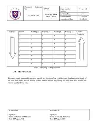


This document provides instructions for an experiment on introducing stepper motors using a PIC microcontroller development board. It describes connecting a stepper motor to a motor driver circuit using a PIC16F877A microcontroller and programming it using MikroC to control the stepper motor's speed and direction by sequentially energizing its coil windings. The document explains stepper motor theory, driver circuits, connection configurations, stepping sequences and motor speed control through programming delays.