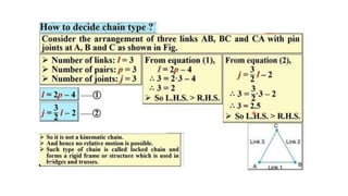
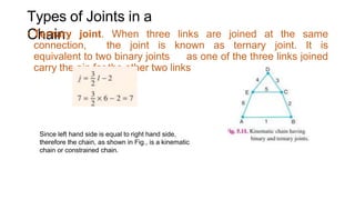
Kinematics of Machinery
(Formally Known as Theory of Machine)
SE Mechanical (2019 Course)
Unit – I
Fundamentals of Mechanism
By
Dr. Somnath Kolgiri
Associate Professor
Mechanical Engineering Department
P G Moze College of Engineering, Wagholi
Kinematic Link or
Element
• Each part of a machine, which moves relative to some other
part, is known as a kinematic link (or simply link) or
element.
• Link may consist of several parts, which are rigidly
fastened together, A link or element need not to be a rigid
body, but it must be a resistant body.
Video on describing kinematic link
Characteristics of the link
• 1. It should have relative motion,
and
• 2. It must be a resistant body.
Types of
Links
• Rigid link. A rigid link is one which does not undergo any
deformation while transmitting motion.
• Flexible link. A flexible link is one which is partly deformed in a
manner not to affect the transmission of motion. For example,
belts, ropes, chains and wires are flexible links and
transmit tensile forces only
• Fluid link. A fluid link is one which is formed by having a
fluid in a receptacle and the motion is transmitted through
the fluid by pressure or compression only, as in the
case of hydraulic presses, jacks and brakes.
Video on braking system
Structure
• It is an assemblage of a number of resistant bodies (known as
members) having no relative motion between them and meant
for carrying loads having straining action. A railway bridge, a
roof truss, machine frames etc., are the examples of a
structure.
Types of Constrained Motions
• Completely constrained motion. When the motion between a
pair is limited to a definite direction irrespective of the
direction of force applied, then the motion is said to be a
completely constrained motion.
• Incompletely constrained motion. When the motion between
a pair can take place in more than one direction, then the
motion is called an incompletely constrained motion.
• Successfully constrained motion. The motions which is
incompletely constrained type, by some external means it
becomes completely constrained.
Video Explaining Constrained motions
Kinematic
Pair
Kinematic Pair : The two links or elements of a machine,
when in contact with each other, are said to form a pair. If the
relative motion between them is completely or successfully
constrained (i.e. in a definite direction), the pair is known as
kinematic pair.
Classification of Kinematic
Pairs
• 1. According to the type of relative motion between the
elements.
a. Sliding pair. When the two elements of a pair are
connected in such a way that one can only slide relative
to the other, the pair is known as a sliding pair.
b. Turning pair. When the two elements of a pair are
connected in such a way that one can only turn or revolve
about a fixed axis of another link, the pair is known as turning
pair.
c. Rolling pair. When the two elements of a pair are
connected in such a way that one rolls over another fixed
link, the pair is known as rolling pair
Classification of Kinematic
Pairs
d. Screw pair. When the two elements of a pair are connected
in such a way that one element can turn about the other by
screw threads, the pair is known as screw pair
e. Spherical pair. When the two elements of a pair are
connected in such a way that one element (with spherical
shape) turns or swivels about the other fixed element
Classification of Kinematic
Pairs
• 2. According to the type of contact between the elements
a) Lower pair. When the two elements of a pair have a
surface contact when relative motion takes place and the
surface of one element slides over the surface of the other.
b) Higher pair. When the two elements of a pair have a line or
point contact when relative motion takes place and the
motion between the two elements is partly turning and partly
sliding
Classification of Kinematic
Pairs
• 3. According to the type of closure
a) Self closed pair. When the two elements of a pair are
connected together mechanically in such a way that only
required kind of relative motion occurs
b) Force - closed pair. When the two elements of a pair
are not connected mechanically but are kept in contact by
the action of external forces
lower pair
• A lower pair is one in which there occurs a surface or area
contact between two members,
Animations for describing of kinematic
pairs
Kinematic
Chain
• In mechanical engineering, a kinematic chain is an assembly of
rigid bodies connected by joints to provide constrained (or
desired) motion
Example 2
Types of Joints in a Chain
• 1. Binary joint: When two links are joined at the same
connection, the joint is known as binary joint. For
example, a chain as shown in Fig, has four links and four
binary joins at A, B,C and D.
Types of Joints in a
Chain
• Ternary joint. When three links are joined at the same
connection, the joint is known as ternary joint. It is
equivalent to two binary joints as one of the three links joined
carry the pin for the other two links
Since left hand side is equal to right hand side,
therefore the chain, as shown in Fig., is a kinematic
chain or constrained chain.
Types of Joints in a Chain
• 3. Quaternary joint: When four links are joined at the
same connection, the joint is called a quaternary joint. It
is equivalent to three binary joints
Example
Homewor
k
• Specify the figure below which type of kinematic chain and
why?
Reference
• Khurmi, R. S., & Gupta, J. K. (2005). A textbook of machine
design. S. Chand publishing.
• https://www.youtube.com/watch?v=aCm66igL2s4
• https://www.youtube.com/watch?v=cU1PLmkjwIg
• https://www.youtube.com/watch?v=sNLaKPCY-bM

Kom_Unit1.pptx

  • 1.
    Kinematics of Machinery (FormallyKnown as Theory of Machine) SE Mechanical (2019 Course) Unit – I Fundamentals of Mechanism By Dr. Somnath Kolgiri Associate Professor Mechanical Engineering Department P G Moze College of Engineering, Wagholi
  • 2.
    Kinematic Link or Element •Each part of a machine, which moves relative to some other part, is known as a kinematic link (or simply link) or element. • Link may consist of several parts, which are rigidly fastened together, A link or element need not to be a rigid body, but it must be a resistant body.
  • 3.
    Video on describingkinematic link
  • 4.
    Characteristics of thelink • 1. It should have relative motion, and • 2. It must be a resistant body.
  • 5.
    Types of Links • Rigidlink. A rigid link is one which does not undergo any deformation while transmitting motion. • Flexible link. A flexible link is one which is partly deformed in a manner not to affect the transmission of motion. For example, belts, ropes, chains and wires are flexible links and transmit tensile forces only • Fluid link. A fluid link is one which is formed by having a fluid in a receptacle and the motion is transmitted through the fluid by pressure or compression only, as in the case of hydraulic presses, jacks and brakes.
  • 6.
  • 7.
    Structure • It isan assemblage of a number of resistant bodies (known as members) having no relative motion between them and meant for carrying loads having straining action. A railway bridge, a roof truss, machine frames etc., are the examples of a structure.
  • 10.
    Types of ConstrainedMotions • Completely constrained motion. When the motion between a pair is limited to a definite direction irrespective of the direction of force applied, then the motion is said to be a completely constrained motion. • Incompletely constrained motion. When the motion between a pair can take place in more than one direction, then the motion is called an incompletely constrained motion. • Successfully constrained motion. The motions which is incompletely constrained type, by some external means it becomes completely constrained.
  • 11.
  • 12.
    Kinematic Pair Kinematic Pair :The two links or elements of a machine, when in contact with each other, are said to form a pair. If the relative motion between them is completely or successfully constrained (i.e. in a definite direction), the pair is known as kinematic pair.
  • 13.
    Classification of Kinematic Pairs •1. According to the type of relative motion between the elements. a. Sliding pair. When the two elements of a pair are connected in such a way that one can only slide relative to the other, the pair is known as a sliding pair. b. Turning pair. When the two elements of a pair are connected in such a way that one can only turn or revolve about a fixed axis of another link, the pair is known as turning pair. c. Rolling pair. When the two elements of a pair are connected in such a way that one rolls over another fixed link, the pair is known as rolling pair
  • 14.
    Classification of Kinematic Pairs d.Screw pair. When the two elements of a pair are connected in such a way that one element can turn about the other by screw threads, the pair is known as screw pair e. Spherical pair. When the two elements of a pair are connected in such a way that one element (with spherical shape) turns or swivels about the other fixed element
  • 15.
    Classification of Kinematic Pairs •2. According to the type of contact between the elements a) Lower pair. When the two elements of a pair have a surface contact when relative motion takes place and the surface of one element slides over the surface of the other. b) Higher pair. When the two elements of a pair have a line or point contact when relative motion takes place and the motion between the two elements is partly turning and partly sliding
  • 16.
    Classification of Kinematic Pairs •3. According to the type of closure a) Self closed pair. When the two elements of a pair are connected together mechanically in such a way that only required kind of relative motion occurs b) Force - closed pair. When the two elements of a pair are not connected mechanically but are kept in contact by the action of external forces
  • 17.
    lower pair • Alower pair is one in which there occurs a surface or area contact between two members,
  • 18.
    Animations for describingof kinematic pairs
  • 19.
    Kinematic Chain • In mechanicalengineering, a kinematic chain is an assembly of rigid bodies connected by joints to provide constrained (or desired) motion
  • 23.
  • 24.
    Types of Jointsin a Chain • 1. Binary joint: When two links are joined at the same connection, the joint is known as binary joint. For example, a chain as shown in Fig, has four links and four binary joins at A, B,C and D.
  • 25.
    Types of Jointsin a Chain • Ternary joint. When three links are joined at the same connection, the joint is known as ternary joint. It is equivalent to two binary joints as one of the three links joined carry the pin for the other two links Since left hand side is equal to right hand side, therefore the chain, as shown in Fig., is a kinematic chain or constrained chain.
  • 26.
    Types of Jointsin a Chain • 3. Quaternary joint: When four links are joined at the same connection, the joint is called a quaternary joint. It is equivalent to three binary joints
  • 27.
  • 28.
    Homewor k • Specify thefigure below which type of kinematic chain and why?
  • 29.
    Reference • Khurmi, R.S., & Gupta, J. K. (2005). A textbook of machine design. S. Chand publishing. • https://www.youtube.com/watch?v=aCm66igL2s4 • https://www.youtube.com/watch?v=cU1PLmkjwIg • https://www.youtube.com/watch?v=sNLaKPCY-bM