This document provides instructions for removing and installing a clutch assembly on TM2187 tractors. The key steps include:
1. Separating the engine from the clutch housing.
2. Removing six cap screws and the clutch assembly. Inspecting components and making any necessary repairs.
3. Installing the clutch assembly over the PTO clutch disk using an alignment tool, then tightening the cap screws and checking rotation.
4. Reinstalling the engine to the clutch housing.
Symptoms like intermittent starting and key recognition errors signal potential problems with your Mercedes’ EIS. Use diagnostic steps like error code checks and spare key tests. Professional diagnosis and solutions like EIS replacement ensure safe driving. Consult a qualified technician for accurate diagnosis and repair.
What Does the PARKTRONIC Inoperative, See Owner's Manual Message Mean for You...Autohaus Service and Sales
Learn what "PARKTRONIC Inoperative, See Owner's Manual" means for your Mercedes-Benz. This message indicates a malfunction in the parking assistance system, potentially due to sensor issues or electrical faults. Prompt attention is crucial to ensure safety and functionality. Follow steps outlined for diagnosis and repair in the owner's manual.
𝘼𝙣𝙩𝙞𝙦𝙪𝙚 𝙋𝙡𝙖𝙨𝙩𝙞𝙘 𝙏𝙧𝙖𝙙𝙚𝙧𝙨 𝙞𝙨 𝙫𝙚𝙧𝙮 𝙛𝙖𝙢𝙤𝙪𝙨 𝙛𝙤𝙧 𝙢𝙖𝙣𝙪𝙛𝙖𝙘𝙩𝙪𝙧𝙞𝙣𝙜 𝙩𝙝𝙚𝙞𝙧 𝙥𝙧𝙤𝙙𝙪𝙘𝙩𝙨. 𝙒𝙚 𝙝𝙖𝙫𝙚 𝙖𝙡𝙡 𝙩𝙝𝙚 𝙥𝙡𝙖𝙨𝙩𝙞𝙘 𝙜𝙧𝙖𝙣𝙪𝙡𝙚𝙨 𝙪𝙨𝙚𝙙 𝙞𝙣 𝙖𝙪𝙩𝙤𝙢𝙤𝙩𝙞𝙫𝙚 𝙖𝙣𝙙 𝙖𝙪𝙩𝙤 𝙥𝙖𝙧𝙩𝙨 𝙖𝙣𝙙 𝙖𝙡𝙡 𝙩𝙝𝙚 𝙛𝙖𝙢𝙤𝙪𝙨 𝙘𝙤𝙢𝙥𝙖𝙣𝙞𝙚𝙨 𝙗𝙪𝙮 𝙩𝙝𝙚 𝙜𝙧𝙖𝙣𝙪𝙡𝙚𝙨 𝙛𝙧𝙤𝙢 𝙪𝙨.
Over the 10 years, we have gained a strong foothold in the market due to our range's high quality, competitive prices, and time-lined delivery schedules.
Why Is Your BMW X3 Hood Not Responding To Release CommandsDart Auto
Experiencing difficulty opening your BMW X3's hood? This guide explores potential issues like mechanical obstruction, hood release mechanism failure, electrical problems, and emergency release malfunctions. Troubleshooting tips include basic checks, clearing obstructions, applying pressure, and using the emergency release.
Core technology of Hyundai Motor Group's EV platform 'E-GMP'Hyundai Motor Group
What’s the force behind Hyundai Motor Group's EV performance and quality?
Maximized driving performance and quick charging time through high-density battery pack and fast charging technology and applicable to various vehicle types!
Discover more about Hyundai Motor Group’s EV platform ‘E-GMP’!
Things to remember while upgrading the brakes of your carjennifermiller8137
Upgrading the brakes of your car? Keep these things in mind before doing so. Additionally, start using an OBD 2 GPS tracker so that you never miss a vehicle maintenance appointment. On top of this, a car GPS tracker will also let you master good driving habits that will let you increase the operational life of your car’s brakes.
5 Warning Signs Your BMW's Intelligent Battery Sensor Needs AttentionBertini's German Motors
IBS monitors and manages your BMW’s battery performance. If it malfunctions, you will have to deal with an array of electrical issues in your vehicle. Recognize warning signs like dimming headlights, frequent battery replacements, and electrical malfunctions to address potential IBS issues promptly.
What Does the Active Steering Malfunction Warning Mean for Your BMWTanner Motors
Discover the reasons why your BMW’s Active Steering malfunction warning might come on. From electrical glitches to mechanical failures and software anomalies, addressing these promptly with professional inspection and maintenance ensures continued safety and performance on the road, maintaining the integrity of your driving experience.
In this presentation, we have discussed a very important feature of BMW X5 cars… the Comfort Access. Things that can significantly limit its functionality. And things that you can try to restore the functionality of such a convenient feature of your vehicle.
"Trans Failsafe Prog" on your BMW X5 indicates potential transmission issues requiring immediate action. This safety feature activates in response to abnormalities like low fluid levels, leaks, faulty sensors, electrical or mechanical failures, and overheating.
Comprehensive program for Agricultural Finance, the Automotive Sector, and Empowerment . We will define the full scope and provide a detailed two-week plan for identifying strategic partners in each area within Limpopo, including target areas.:
1. Agricultural : Supporting Primary and Secondary Agriculture
• Scope: Provide support solutions to enhance agricultural productivity and sustainability.
• Target Areas: Polokwane, Tzaneen, Thohoyandou, Makhado, and Giyani.
2. Automotive Sector: Partnerships with Mechanics and Panel Beater Shops
• Scope: Develop collaborations with automotive service providers to improve service quality and business operations.
• Target Areas: Polokwane, Lephalale, Mokopane, Phalaborwa, and Bela-Bela.
3. Empowerment : Focusing on Women Empowerment
• Scope: Provide business support support and training to women-owned businesses, promoting economic inclusion.
• Target Areas: Polokwane, Thohoyandou, Musina, Burgersfort, and Louis Trichardt.
We will also prioritize Industrial Economic Zone areas and their priorities.
Sign up on https://profilesmes.online/welcome/
To be eligible:
1. You must have a registered business and operate in Limpopo
2. Generate revenue
3. Sectors : Agriculture ( primary and secondary) and Automative
Women and Youth are encouraged to apply even if you don't fall in those sectors.
What Exactly Is The Common Rail Direct Injection System & How Does It WorkMotor Cars International
Learn about Common Rail Direct Injection (CRDi) - the revolutionary technology that has made diesel engines more efficient. Explore its workings, advantages like enhanced fuel efficiency and increased power output, along with drawbacks such as complexity and higher initial cost. Compare CRDi with traditional diesel engines and discover why it's the preferred choice for modern engines.
What Exactly Is The Common Rail Direct Injection System & How Does It Work
John deere 5603 tractor service repair technical manual (tm2187)
1. TM2187 - 5225, 5325, 5425, 5525, 5625, and 5603 Tractors Repair
Technical Manual
Remove and Install Clutch Assembly
Remove and Install Clutch Assembly
NOTE:
Clutch assembly can be removed and installed without any finger adjustment procedures.
If clutch assembly has been disassembled for inspection or repair, see PTO Clutch Finger Adjustment
and Traction Clutch Finger Adjustment procedures in Section 50, Group 10.
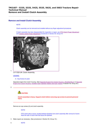
1.
LV11252-UN: Clutch Assembly
LEGEND:
A - Cap Screw (6 used)
Separate engine from clutch housing. (See Separate Engine from Clutch Housing—Straddle Mount or Separate
Engine from Clutch Housing—Isolated Open Operator Station and Cab Tractors in Section 50, Group 05.)
2.
CAUTION:
Clutch assembly is heavy. Support clutch before removing cap screws to prevent personal
injury.
Remove six cap screws (A) and clutch assembly.
NOTE:
PTO clutch disk is loose, located between flywheel and clutch assembly after removal of clutch.
Note the side of clutch disk that faces the flywheel.
3. Make repairs as necessary. (See procedures in Section 50, Group 10.)
4. NOTE:
1/4
2020/1/4file:///C:/ProgramData/Service%20ADVISOR/Temp/TM2187_09001faa802bbf...
2. 5-cylinder tractors, from factory, are equipped with standard three-pad PTO clutch disk. All tractors
are serviced with high-capacity four-pad PTO clutch disk.
Inspect and replace PTO clutch disk if friction surfaces are contaminated with grease or oil, or if thickness of disk is not
within specifications.
5.
LV11253-UN: Fly Wheel/Pilot Bearing
LEGEND:
A - Pilot Bearing
Inspect pilot bearing (A) for wear or damage. Replace if necessary. (See procedure in CTM104 or CTM301.)
6. IMPORTANT:
When installing the PTO clutch disk (A), make sure the side of the disk stamped “Flywheel Side” faces
the engine flywheel and that the alignment pins (B) face the rear of the tractor.
NOTE:
To aid during installation of clutch assembly to flywheel, use JDG689 clutch alignment tool (D) to
align and rotate PTO clutch disk (A) while the clutch cap screws are being tightened.
Item Measurement Specification
PTO Clutch Disk Thickness 7.6—6.6 mm (0.300—0.260 in.)
2/4
2020/1/4file:///C:/ProgramData/Service%20ADVISOR/Temp/TM2187_09001faa802bbf...
4. LV8839-UN: JDG689 Alignment Tool
LEGEND:
A - PTO Clutch Disk
B - Alignment Pin (4 used)
C - Clutch Assembly
D - Clutch Alignment Tool JDG689
Install and position the PTO clutch disk (A) against the flywheel. Make sure the alignment pins (B) are facing away
from engine.
7. Install the clutch assembly (C) over PTO clutch disk (A) using JDG689 Clutch Alignment Tool. Install cap screws and
evenly tighten in a crisscross pattern to specification.
8. After cap screws are tightened to specifications, make sure PTO clutch disk rotates freely. Remove clutch alignment
tool.
9. Install engine to clutch housing. (See Install Engine to Clutch Housing—Straddle Mount or Install Engine to Clutch
Housing—Isolated Open Operator Station and Cab Tractors in Section 50, Group 05.)
Item Measurement Specification
Clutch Assembly Mounting Cap
Screw
Torque 36 N˙m (27 lb-ft)
JG31785,00000E6-19-20041012
4/4
2020/1/4file:///C:/ProgramData/Service%20ADVISOR/Temp/TM2187_09001faa802bbf...
5. TM2187 - 5225, 5325, 5425, 5525, 5625, and 5603 Tractors Repair
Technical Manual
Disassemble and Inspect Clutch Assembly
Disassemble and Inspect Clutch Assembly
LV5351-UN: PTO Pressure Plate
LV4660-UN: Clutch
LEGEND:
A - Lock Nut (3 used)
B - PTO Pressure Plate
C - Spring (3 used)
D - Washer (3 used)
1/9
2020/1/4file:///C:/ProgramData/Service%20ADVISOR/Temp/TM2187_09001faa802bbf...
6. 1. NOTE:
Do not reuse three lock nuts (A). New lock nuts are available through the parts catalog.
Remove three lock nuts (A) and PTO pressure plate (B). Discard three lock nuts (A) after removal.
2. Clean any rust or oil from PTO pressure plate drive surface. Inspect drive surface for distortion, cracks and heat
damage. Replace if necessary.
3. Remove three springs (C) and washers (D).
4. NOTE:
The heads of three adjustable socket head screws (A) on JDG1337 Clutch Repair Fixture are
used to support the clutch assembly on a flat surface during disassembly.
LV4661-UN: Support Plate
LEGEND:
A - Adjustable Socket Head Screw (3 used)
B - Clutch Support Plate (Part of JDG1337)
C - Machined Surface
Install the clutch support plate (B) flush with machined surface (C) on back of clutch.
2/9
2020/1/4file:///C:/ProgramData/Service%20ADVISOR/Temp/TM2187_09001faa802bbf...
7. 5.
LV4662-UN: Compression Plate
LV4664-UN: Repair Fixture
LEGEND:
A - Compression Plate (Part of JDG1337)
B - Bolt (6 used)
C - Large Spring Washer
D - Bolt
E - Spring Washer Retainer (6 used)
Position clutch and support plate on flat work area.
3/9
2020/1/4file:///C:/ProgramData/Service%20ADVISOR/Temp/TM2187_09001faa802bbf...
8. 6. Install compression plate (A) on flywheel side of clutch. Adjust all six bolts (B) until touching large spring washer (C).
7. Make sure all six bolts (B) are resting on large spring washer (C) and not on any of the six spring washer retainers (E)
located around the clutch.
8. Finger-tighten bolt (D) into threaded hole in center of bottom support plate.
9. IMPORTANT:
Use short bursts from a pneumatic impact wrench to tighten bolt in center of clutch compression plate
until all six spring washer retainers can be removed.
LV4665-UN: Tighten Compression Plate
LEGEND:
A - Bolt
B - Large Spring Washer
C - Retainer (6 used)
Slowly tighten bolt (A) in center of compression plate to compress large spring washer (B) and remove six spring
washer retainers (C).
10. After all six spring washer retainers (C) have been removed, slowly loosen bolt (A) to relieve tension of large spring
washer (B).
11. Remove clutch compression plate from clutch assembly.
4/9
2020/1/4file:///C:/ProgramData/Service%20ADVISOR/Temp/TM2187_09001faa802bbf...
9. 12.
LV4667-UN: Large Spring Washer
LV4668-UN: Traction Clutch Pressure Plate
LEGEND:
A - Spring Washer
B - Ring
C - Traction Clutch Front Pressure Plate
D - Lock Nut and Cap Screw (3 used)
Remove spring washer (A) and ring (B).
13. NOTE:
5/9
2020/1/4file:///C:/ProgramData/Service%20ADVISOR/Temp/TM2187_09001faa802bbf...
10. Do not loosen or remove three lock nuts and cap screws (D) on traction clutch front pressure plate
(C).
Remove traction clutch front pressure plate (C).
14. Clean any rust or oil from traction clutch front pressure plate drive surface. Inspect drive surface for distortion, cracks
and heat damage. Replace if necessary.
15. NOTE:
Note the direction of raised center hub (B) to aid during installation.
LV5375-UN: Traction Clutch Disk
LEGEND:
A - Traction Clutch Disk
B - Center Hub
Remove traction clutch disk (A). Note the direction of center hub (B) on disk (A) to aid during installation.
16. IMPORTANT:
During inspection, if traction clutch disk thickness is within 6—6.25 mm (0.235—0.246 in.), it is
recommended that the traction clutch disk be replaced.
Inspect and replace traction clutch disk if friction surfaces are contaminated with grease or oil or if thickness of disk is
not within specification.
Item Measurement Specification
Traction Clutch Disk Thickness 10—6 mm (0.395—0.235 in.)
6/9
2020/1/4file:///C:/ProgramData/Service%20ADVISOR/Temp/TM2187_09001faa802bbf...
11. 17.
LV5379-UN: Machine Pressure Plates
LEGEND:
A - PTO Clutch Pressure Plate
B - Traction Clutch Front Pressure Plate
C - Traction Clutch Rear Pressure Plate
Machine drive surfaces of pressure plates, if necessary, until surface is free of scores, cracks and heat discoloration.
18. Measure the thickness of pressure plates at dimensions (A, B and C). Replace parts that are not within specification.
Item Measurement Specification
Clutch Pressure Plate
PTO Clutch Pressure Plate Thickness 16.2 mm (0.638 in.) minimum
Traction Clutch Front Pressure Plate Thickness 26.7 mm (1.051 in.) minimum
Traction Clutch Rear Pressure Plate Thickness 15.8 mm (0.622 in.) minimum
7/9
2020/1/4file:///C:/ProgramData/Service%20ADVISOR/Temp/TM2187_09001faa802bbf...
12. 19. NOTE:
Bushing (D) is crimped. If replacing bushing, make sure new bushing is securely crimped to pin
(F).
PTO clutch and traction clutch finger assemblies are serviced as separate kits. Kits are available
through the parts catalog.
LV4649-UN: Clutch Release Fingers
LEGEND:
A - Traction Clutch Rear Pressure Plate
B - Adjuster (3 used)
C - Bushing (6 used)
D - Bushing (12 used)
E - Traction Clutch Release Finger (3 used)
F - Pin (6 used)
G - Pin (6 used)
H - Spring (3 used)
I - Spring (3 used)
J - PTO Clutch Release Finger (3 used)
K - Adjuster (3 used)
L - Bushing (3 used)
8/9
2020/1/4file:///C:/ProgramData/Service%20ADVISOR/Temp/TM2187_09001faa802bbf...
13. Disassemble parts (A—L).
20. Inspect all parts for wear or damage. Replace as necessary.
21. Crimp new bushing (D) to pin (F).
22. Clean any rust or oil from traction clutch rear pressure plate drive surface. Inspect drive surface for distortion, cracks
and heat damage. Replace if necessary.
JG31785,00000E7-19-20041012
9/9
2020/1/4file:///C:/ProgramData/Service%20ADVISOR/Temp/TM2187_09001faa802bbf...
14. Thank you very much for
your reading. Please Click
Here. Then Get COMPLETE
MANUAL. NO WAITING
NOTE:
If there is no response to
click on the link above,
please download the PDF
document first and then
click on it.
15. TM2187 - 5225, 5325, 5425, 5525, 5625, and 5603 Tractors Repair
Technical Manual
Assemble Clutch Assembly
Assemble Clutch Assembly
1.
LV4661-UN: Support Plate
LEGEND:
A - Adjustable Socket Head Screw (3 used)
B - Clutch Support Plate (Part of JDG1337)
C - Machined Surface
Install support plate (B) flush with machined surface (C) on clutch.
2. Make sure adjustable socket head screws (A) all have equal lengths.
3. Place support plate and clutch on flat work area.
4. NOTE:
Make sure raised hub side of traction clutch disk is facing downward.
Traction clutch disk (A) will align with threaded hub in center of support plate from JDG1337
Clutch Repair Fixture.
1/7
2020/1/4file:///C:/ProgramData/Service%20ADVISOR/Temp/TM2187_09001faa802bbf...
16. LV5375-UN: Traction Clutch Disk
LV4668-UN: Front Pressure Plate
LEGEND:
A - Traction Clutch Disk
B - Raised Hub
C - Traction Clutch Front Pressure Plate
D - Cap Screw (3 used)
Install traction clutch disk (A) with raised hub (B) side downward.
5. Install traction clutch front pressure plate (C). Make sure cap screws (D) seat inside adjusters.
2/7
2020/1/4file:///C:/ProgramData/Service%20ADVISOR/Temp/TM2187_09001faa802bbf...
17. 6.
LV1611-UN: Spring Washer Free Height
LEGEND:
A - Spring Washer
B - Free Height Dimension
Place spring washer (A) on a workbench or any flat surface and measure free height dimension (B). Replace spring
washer if less than specification.
7.
LV4667-UN: Spring Washer and Ring
LEGEND:
Item Measurement Specification
Clutch Spring Washer Height 13 mm (0.512 in.)
3/7
2020/1/4file:///C:/ProgramData/Service%20ADVISOR/Temp/TM2187_09001faa802bbf...