Why Is Your BMW X3 Hood Not Responding To Release CommandsDart Auto
Experiencing difficulty opening your BMW X3's hood? This guide explores potential issues like mechanical obstruction, hood release mechanism failure, electrical problems, and emergency release malfunctions. Troubleshooting tips include basic checks, clearing obstructions, applying pressure, and using the emergency release.
Symptoms like intermittent starting and key recognition errors signal potential problems with your Mercedes’ EIS. Use diagnostic steps like error code checks and spare key tests. Professional diagnosis and solutions like EIS replacement ensure safe driving. Consult a qualified technician for accurate diagnosis and repair.
Comprehensive program for Agricultural Finance, the Automotive Sector, and Empowerment . We will define the full scope and provide a detailed two-week plan for identifying strategic partners in each area within Limpopo, including target areas.:
1. Agricultural : Supporting Primary and Secondary Agriculture
• Scope: Provide support solutions to enhance agricultural productivity and sustainability.
• Target Areas: Polokwane, Tzaneen, Thohoyandou, Makhado, and Giyani.
2. Automotive Sector: Partnerships with Mechanics and Panel Beater Shops
• Scope: Develop collaborations with automotive service providers to improve service quality and business operations.
• Target Areas: Polokwane, Lephalale, Mokopane, Phalaborwa, and Bela-Bela.
3. Empowerment : Focusing on Women Empowerment
• Scope: Provide business support support and training to women-owned businesses, promoting economic inclusion.
• Target Areas: Polokwane, Thohoyandou, Musina, Burgersfort, and Louis Trichardt.
We will also prioritize Industrial Economic Zone areas and their priorities.
Sign up on https://profilesmes.online/welcome/
To be eligible:
1. You must have a registered business and operate in Limpopo
2. Generate revenue
3. Sectors : Agriculture ( primary and secondary) and Automative
Women and Youth are encouraged to apply even if you don't fall in those sectors.
What Does the PARKTRONIC Inoperative, See Owner's Manual Message Mean for You...Autohaus Service and Sales
Learn what "PARKTRONIC Inoperative, See Owner's Manual" means for your Mercedes-Benz. This message indicates a malfunction in the parking assistance system, potentially due to sensor issues or electrical faults. Prompt attention is crucial to ensure safety and functionality. Follow steps outlined for diagnosis and repair in the owner's manual.
𝘼𝙣𝙩𝙞𝙦𝙪𝙚 𝙋𝙡𝙖𝙨𝙩𝙞𝙘 𝙏𝙧𝙖𝙙𝙚𝙧𝙨 𝙞𝙨 𝙫𝙚𝙧𝙮 𝙛𝙖𝙢𝙤𝙪𝙨 𝙛𝙤𝙧 𝙢𝙖𝙣𝙪𝙛𝙖𝙘𝙩𝙪𝙧𝙞𝙣𝙜 𝙩𝙝𝙚𝙞𝙧 𝙥𝙧𝙤𝙙𝙪𝙘𝙩𝙨. 𝙒𝙚 𝙝𝙖𝙫𝙚 𝙖𝙡𝙡 𝙩𝙝𝙚 𝙥𝙡𝙖𝙨𝙩𝙞𝙘 𝙜𝙧𝙖𝙣𝙪𝙡𝙚𝙨 𝙪𝙨𝙚𝙙 𝙞𝙣 𝙖𝙪𝙩𝙤𝙢𝙤𝙩𝙞𝙫𝙚 𝙖𝙣𝙙 𝙖𝙪𝙩𝙤 𝙥𝙖𝙧𝙩𝙨 𝙖𝙣𝙙 𝙖𝙡𝙡 𝙩𝙝𝙚 𝙛𝙖𝙢𝙤𝙪𝙨 𝙘𝙤𝙢𝙥𝙖𝙣𝙞𝙚𝙨 𝙗𝙪𝙮 𝙩𝙝𝙚 𝙜𝙧𝙖𝙣𝙪𝙡𝙚𝙨 𝙛𝙧𝙤𝙢 𝙪𝙨.
Over the 10 years, we have gained a strong foothold in the market due to our range's high quality, competitive prices, and time-lined delivery schedules.
In this presentation, we have discussed a very important feature of BMW X5 cars… the Comfort Access. Things that can significantly limit its functionality. And things that you can try to restore the functionality of such a convenient feature of your vehicle.
What Does the Active Steering Malfunction Warning Mean for Your BMWTanner Motors
Discover the reasons why your BMW’s Active Steering malfunction warning might come on. From electrical glitches to mechanical failures and software anomalies, addressing these promptly with professional inspection and maintenance ensures continued safety and performance on the road, maintaining the integrity of your driving experience.
5 Warning Signs Your BMW's Intelligent Battery Sensor Needs AttentionBertini's German Motors
IBS monitors and manages your BMW’s battery performance. If it malfunctions, you will have to deal with an array of electrical issues in your vehicle. Recognize warning signs like dimming headlights, frequent battery replacements, and electrical malfunctions to address potential IBS issues promptly.
What Exactly Is The Common Rail Direct Injection System & How Does It WorkMotor Cars International
Learn about Common Rail Direct Injection (CRDi) - the revolutionary technology that has made diesel engines more efficient. Explore its workings, advantages like enhanced fuel efficiency and increased power output, along with drawbacks such as complexity and higher initial cost. Compare CRDi with traditional diesel engines and discover why it's the preferred choice for modern engines.
Core technology of Hyundai Motor Group's EV platform 'E-GMP'Hyundai Motor Group
What’s the force behind Hyundai Motor Group's EV performance and quality?
Maximized driving performance and quick charging time through high-density battery pack and fast charging technology and applicable to various vehicle types!
Discover more about Hyundai Motor Group’s EV platform ‘E-GMP’!
Things to remember while upgrading the brakes of your carjennifermiller8137
Upgrading the brakes of your car? Keep these things in mind before doing so. Additionally, start using an OBD 2 GPS tracker so that you never miss a vehicle maintenance appointment. On top of this, a car GPS tracker will also let you master good driving habits that will let you increase the operational life of your car’s brakes.
"Trans Failsafe Prog" on your BMW X5 indicates potential transmission issues requiring immediate action. This safety feature activates in response to abnormalities like low fluid levels, leaks, faulty sensors, electrical or mechanical failures, and overheating.
John Deere 50D Compact Excavator Service Repair Technical Manual (TM2264).pdf
1. TM2264 - 35D and 50D Excavator
Fuel Injection Pump Remove and Install
Fuel Injection Pump Remove and Install
Fuel Injection Pump Remove
1. IMPORTANT:
Never steam clean or pour cold water on injection pump while the pump is running or warm. Doing so
can damage the pump.
Clean injection lines and area around the injection pump with cleaning solvent or a steam cleaner.
2. Remove radiator, fan, and belt.
See Radiator Remove and Install—35D (S.N. —254999) . (Group 0510.)
See Radiator Remove and Install—35D (S.N. 255000— ) . (Group 0510.)
See Radiator Remove and Install—50D (S.N. —274999) . (Group 0510.)
See Radiator Remove and Install—50D (S.N. 275000— ) . (Group 0510.)
3. Remove intake manifold. See Intake Manifold Remove and Install . (Group 0400.)
4. Lower air conditioning compressor.
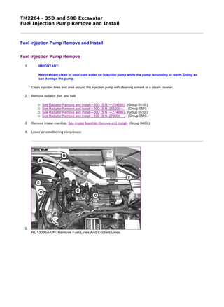
5.
RG13396A-UN: Remove Fuel Lines And Coolant Lines.
1/10
2019/11/19
file:///C:/ProgramData/Service%20ADVISOR/Temp/TM2264_09001faa802a...
2. RG13397A-UN: Injection Pump Gear Cover
RG13398A-UN: Injection Pump Gear Timing Marks
LEGEND:
A - Fuel Inlet Line
B - Fuel Return Line
C - Injector Return Line
D - Coolant Line
E - Coolant Line
F - Fuel Shutoff Solenoid Wire Connector
G - Foam Spacer
H - Cap Screw (4 used)
I - Pump Gear Timing Mark
J - Idler Gear Timing Mark
Disconnect fuel inlet line (A), fuel return line (B), and injector return line (C).
6. Disconnect coolant lines (D and E).
7. Disconnect fuel shutoff solenoid wire connector (F).
8. Remove foam spacer (G).
9. Remove cap screws (H) and remove injection pump gear access cover.
10. NOTE:
For all the timing marks to become aligned, engine may need to be rotated up to fifty-two times.
2/10
2019/11/19
file:///C:/ProgramData/Service%20ADVISOR/Temp/TM2264_09001faa802a...
3. Alignment marks (I and J) are both identified with a stamped letter “B”.
Rotate engine in the direction of rotation until mark (I) on pump gear aligns with mark on idler gear (J) (both identified
by a stamped letter B). Use chalk or paint to mark injection pump gear to idler gear.
11.
RG13399A-UN: Injection Pump Timing Gear
RG13400A-UN: Injection Pump Timing Gear Puller
3/10
2019/11/19
file:///C:/ProgramData/Service%20ADVISOR/Temp/TM2264_09001faa802a...
4. TX1062018A-UN: Injection Pump Timing Marks
LEGEND:
A - Timing Gear Nut and Washer
B - Cap Screw (4 used)
C - Threaded Puller Holes
D - Puller Cap Screw (2 used)
E - Gear Puller
F - Injection Pump Timing Mark
G - Gear Cover Mounting Plate Timing Mark
Remove gear retaining nut and washer (A).
12. IMPORTANT:
Do not loosen or disturb cap screws (B) securing gear to the hub. Gear to hub adjustment is pre-set to
comply with strict EPA emissions requirements and is not adjustable. This procedure is done at the
pump manufacturer and cannot be duplicated in the field.
Install puller (E) into threaded holes (C) on gear using cap screws (D).
13. IMPORTANT:
Engine must not be rotated when timing gear is removed from injection pump shaft. Engine should only
be rotated when timing gear is securely fastened to pump or engine damage could result.
Remove gear and hub assembly from injection pump shaft. Gear will stay inside timing cover.
14. IMPORTANT:
Marks must be made on the injection pump and the gear cover mounting plate to correctly install the
pump. If marks are not made, there will be no way to properly time the injection pump.
Note position of timing marks on gear cover mounting plate (G) and injection pump (F). Pump must be installed at the
exact same timing mark as when removed. Scribe a line as accurately and straight as possible at the pump flange
mark (F) onto the gear cover mounting plate.
4/10
2019/11/19
file:///C:/ProgramData/Service%20ADVISOR/Temp/TM2264_09001faa802a...
5. 15.
RG13402A-UN: Injection Pump Mounting Points
LEGEND:
A - External Lube Line
B - Cap Screw
C - Nut (3 used)
Remove external lube line (A) from pump.
16. Remove cap screw (B).
17. IMPORTANT:
Marks must be made on the injection pump and the gear cover mounting plate to properly install pump.
You must also record the injection pump timing number marked on the pump to correctly install the
pump. If marks are not made and the timing number not recorded, there will be no way to properly time
the injection pump.
Remove pump flange mounting nuts (C) and remove pump.
18. NOTE:
The injection pump timing number is stamped on the engine side of the fuel injection pump
housing. Treat this number as though there is a decimal point between the two digits. (Example 68
= 6.8).
Find and record pump timing number stamped on pump. This number will be needed if pump is being replaced or
recalibrated.
IMPORTANT:
DO NOT attempt to service the injection pump or governor. If unit is in need of repair, it must be serviced
by a qualified EPA/CARB certified fuel injection repair shop. If replacement is necessary, replace entire
unit. Do not rotate engine while injection pump is removed. If engine is rotated, the timing gear cover
must be removed to ensure correct timing.
Pump Installation
5/10
2019/11/19
file:///C:/ProgramData/Service%20ADVISOR/Temp/TM2264_09001faa802a...
6. 1.
RG13399A-UN: Injection Pump Timing Gear
LEGEND:
A - Timing Gear Nut and Washer
B - Cap Screw (4 used)
C - Threaded Puller Holes
Install new O-ring on injection pump.
2. Put injection pump onto back of gear cover mounting plate. Install three mounting nuts. Do not tighten. Align key on
shaft with keyway in gear hub. Ensure gear is still aligned to idler gear.
3. Install nut and washer (A) on pump shaft. Tighten nut to specification.
4.
TX1062057A-UN: Injection Pump Timing Marks
Item Measurement Specification
Fuel Injection Pump Drive Gear
Hub-to-Shaft Retaining Nut
Torque 78—88 N˙m
58—65 lb-ft
6/10
2019/11/19
file:///C:/ProgramData/Service%20ADVISOR/Temp/TM2264_09001faa802a...
7. RG13415A-UN: Injection Pump Mounting
LEGEND:
A - Injection Pump Timing Mark
B - Gear Cover Mounting Plate Timing Mark
C - Pump Mounting Nut (3 used)
D - Cap Screw
E - External Lube Line
Align timing mark on injection pump (A) with correct mark on gear cover mounting plate (B).
5. Tighten three pump mounting nuts (C) to specification.
6. Install cap screw (D). Tighten to specification.
7. Fill pump with engine oil through external lube line port until oil runs out. Install external lube line. Tighten lube line
fitting (E) to specification.
8. Install cover for injection pump timing gear.
Item Measurement Specification
Injection Pump Mounting Nuts Torque 26 N˙m
228 lb-in.
Item Measurement Specification
Injection Pump Mounting Cap
Screw
Torque 26 N˙m
228 lb-in.
Item Measurement Specification
Injection Pump External Lube Line
Fitting
Torque 15 N˙m
133 lb-in.
7/10
2019/11/19
file:///C:/ProgramData/Service%20ADVISOR/Temp/TM2264_09001faa802a...
8. 9.
RG13396A-UN: Install Fuel and Coolant Lines
LEGEND:
A - Fuel Inlet Line
B - Fuel Return Line
C - Injectors Return Line
D - Coolant Line
E - Coolant Line
F - Fuel Shutoff Solenoid Wire Connector
G - Foam Spacer
Install spacer (G) between pump and engine block.
10. Connect fuel shutoff solenoid wire connector (F).
11. Connect fuel lines (A, B, and C).
12. Connect coolant lines (D and E).
13. Install intake manifold. See Intake Manifold Remove and Install . (Group 0400.)
14. Install radiator, fan, and belt.
See Radiator Remove and Install—35D (S.N. —254999) . (Group 0510.)
See Radiator Remove and Install—35D (S.N. 255000— ) . (Group 0510.)
See Radiator Remove and Install—50D (S.N. —274999) . (Group 0510.)
See Radiator Remove and Install—50D (S.N. 275000— ) . (Group 0510.)
New, Rebuilt, or Recalibrated Pump Timing
8/10
2019/11/19
file:///C:/ProgramData/Service%20ADVISOR/Temp/TM2264_09001faa802a...
9. 1.
RG13614-UN: Injection Pump Sticker
LEGEND:
A - Middle 0° Line
B - 1° Line
C - 2° Line
D - 0.5° Line
Install timing mark sticker supplied with pump so that the (A) line is exactly in-line with the mark that was made on the
gear cover mounting plate when the pump was removed.
2. IMPORTANT:
Injection pump timing can not be performed without injection pump timing numbers from original and
replacement pumps. There is no way to properly install the injection pump without these numbers.
Calculate the difference between the timing numbers, recorded earlier, from the original and replacement/recalibrated
pumps. This calculated number will be needed to correctly time the pump.
Example: If the timing number on the replacement/recalibrated pump was 6.0, and the timing number on the original
pump is 4.0 (fuel injection angle of replacement/recalibrated pump) - (fuel injection angle of original pump), the
replacement pump should be timed at the +2.0° (advanced) mark (C) on the new timing mark sticker.
3. NOTE:
Rotating the injection pump away from the cylinder block will advance the timing and rotating the
injection pump toward the cylinder block will delay the timing.
Set the pump to the correct timing mark using the calculated number difference between the original and replacement
pumps. Adjust timing accordingly using the new timing mark sticker.
4. Hold the pump at the correct timing mark and tighten three pump mounting nuts and cap screw to specification.
9/10
2019/11/19
file:///C:/ProgramData/Service%20ADVISOR/Temp/TM2264_09001faa802a...
10. 5. If removed, install timing cover. See Timing Gear Cover Remove and Install . (Group 0400.)
6.
RG13396A-UN: Install Fuel And Coolant Lines
LEGEND:
A - Fuel Inlet Line
B - Fuel Return Line
C - Injectors Return Line
D - Coolant Line
E - Coolant Line
F - Fuel Shutoff Solenoid Wire Connector
G - Foam Spacer
Install spacer (G) between pump and engine block.
7. Connect fuel shutoff solenoid wire connector (F).
8. Connect fuel lines (A, B, and C).
9. Connect coolant lines (D and E).
10. Install intake manifold. See Intake Manifold Remove and Install . (Group 0400.)
11. Install radiator, fan, and belt.
See Radiator Remove and Install—35D (S.N. —254999) . (Group 0510.)
See Radiator Remove and Install—35D (S.N. 255000— ) . (Group 0510.)
See Radiator Remove and Install—50D (S.N. —274999) . (Group 0510.)
See Radiator Remove and Install—50D (S.N. 275000— ) . (Group 0510.)
Item Measurement Specification
Injection Pump Mounting Nuts Torque 26 N˙m
228 lb-in.
Injection Pump Mounting Cap
Screw
Torque 26 N˙m
228 lb-in.
OUO1030,00000CA-19-20090721
10/10
2019/11/19
file:///C:/ProgramData/Service%20ADVISOR/Temp/TM2264_09001faa802a...
11. TM2264 - 35D and 50D Excavator
Fuel Injection Nozzles Remove and Install
Fuel Injection Nozzles Remove and Install
General Nozzle Service Precautions
Before removal, thoroughly remove all dirt from the cylinder head around fuel injection nozzles. Clean with compressed air to
prevent dirt from entering the cylinders. Plug the bore in the cylinder head after each nozzle has been removed. Cap fuel line
openings as soon as they are disconnected.
Immediately fit protective caps over the nozzle tips and the line connections to avoid handling damage and getting debris in
fuel system.
Do not bend the fuel delivery lines, as this may affect their durability. When loosening the fuel pressure lines, hold male union
of nozzle line stationary with a backup wrench.
1. IMPORTANT:
Never steam clean or pour cold water on injection pump while the pump is running or warm. Doing so
can damage the pump.
Clean the injection pump lines and area around the nozzles using a parts cleaning solvent or steam cleaner.
NOTE:
Nozzles are matched to the cylinders. If removing more than one nozzle, tag each nozzle,
according to the cylinder from which it was removed.
1/3
2019/11/19
file:///C:/ProgramData/Service%20ADVISOR/Temp/TM2264_09001faa802a...
12. 2.
RG13407-UN: Fuel Injector Components
LEGEND:
A - Cap Screw and Washer
B - Retaining Plate
C - Hose Clamp
D - Leak-Off Hose
E - Injection Nozzle
F - Ring
G - Heat Protector
Loosen fuel injection line connectors-to-nozzles slightly to release pressure in the fuel system.
3. Loosen line clamp(s) and remove fuel injection lines.
4. Remove clamps (C) and leak-off hoses (D).
5. Remove cap screw and washer (A) and retaining plate (B).
6. Remove injection nozzle (E), ring (F), and TEFLON ® heat protector (G). If ring and protector stay in cylinder head,
thread a cap screw into protector and pull from cylinder head.
2/3
2019/11/19
file:///C:/ProgramData/Service%20ADVISOR/Temp/TM2264_09001faa802a...
13. 7.
M82126A-UN: If Nozzles Stick in Cylinder Head
LEGEND:
A - Large Flat Washer
B - Nut (2 used)
C - Cap Screw
D - Old Injection Line Nut
E - Injection Nozzle
If nozzles are stuck in cylinder head:
Grind the head of a cap screw (C) so it fits inside a nut from an old injection line (D).
Use two nuts (B) to attach a large flat washer (A) to the cap screw.
Install assembly onto nozzle and use a puller and slide hammer to pull nozzle from cylinder head.
8. Test injection nozzles. Perform Fuel Injection Nozzle Check . (Group 9010-25.)
9. Installation is done in the reverse order of removal.
10. Tighten retaining plate nuts.
Item Measurement Specification
Fuel Injection Retaining Plate Cap
Screw
Torque 24—28 N˙m
212—248 lb-in
TEFLON is a trademark of Du Pont Co. OUO1030,00000CB-19-20051128
3/3
2019/11/19
file:///C:/ProgramData/Service%20ADVISOR/Temp/TM2264_09001faa802a...
14. TM2264 - 35D and 50D Excavator
Fuel Injection Nozzles Disassemble and Assemble
Fuel Injection Nozzles Disassemble and Assemble
Fuel Injection Nozzles Disassemble
RG11097A-UN: Hole-Type Nozzle
LEGEND:
A - Injector Body
B - Shims
C - Spring
D - Spring Seat
E - Separator Plate
F - Nozzle Valve
G - Nozzle Body
H - Retaining Nut
I - Index Pin (2 used)
NOTE:
If servicing more than one nozzle, keep parts for each nozzle separate from one another.
1. Disassemble fuel injection nozzles.
1/5
2019/11/19
file:///C:/ProgramData/Service%20ADVISOR/Temp/TM2264_09001faa802a...
15. 2. IMPORTANT:
If injection nozzles are disassembled to be cleaned, the same number and thickness of shims must be
installed.
Clean and inspect nozzle components.
Fuel Injection Nozzles Clean and Inspect
2/5
2019/11/19
file:///C:/ProgramData/Service%20ADVISOR/Temp/TM2264_09001faa802a...
17. M82326B-UN: Nozzle Body, Separator Plate, Contact & Sealing Surfaces
LEGEND:
A - Injector Body
B - Fuel Return Pipe
C - Shims
D - Spring
E - Index Pin
F - Separator Plate
G - Nozzle Body
H - Nozzle Valve
I - Retaining Nut
J - Spring Seat
K - Nozzle Contact Surfaces
L - Sealing Surfaces
NOTE:
To clean nozzles properly, JDF13B Nozzle Cleaning Kit is recommended. The cleaning kit is available
through the John Deere SERVICEGARD ™ Catalog.
1. Remove anti-corrosive grease from new or reconditioned nozzles by washing them thoroughly in diesel fuel.
2. IMPORTANT:
Never use a steel brush to clean nozzles as this will distort the spray hole.
Remove carbon from used nozzles, and clean by washing in diesel fuel. If parts are coated with hardened carbon or
lacquer, it may be necessary to use a brass wire brush (supplied in nozzle cleaning kit).
3. After removing carbon or lacquer from the exterior of nozzle, inspect sealing surfaces between separator plate and
nozzle body for nicks or scratches.
4. Inspect condition of separator plate and nozzle body. Contact area of separator plate (both parts) must not be scored
or pitted. Use an inspection magnifier to aid in making the inspection.
5. Check nozzle contact surface on separator plate for wear. If contact surface is more than specification, replace nozzle
assembly.
6. Inspect the piston (large) part of nozzle valve to see that it is not scratched or scored and that lower (tip) end of valve
is not broken. If any of these conditions are present, replace the nozzle assembly.
Item Measurement Specification
Fuel Injection Nozzle Contact
Surface
Size 0.10 mm
0.0039 in.
4/5
2019/11/19
file:///C:/ProgramData/Service%20ADVISOR/Temp/TM2264_09001faa802a...
18. 7.
M35919-UN: Nozzle Valve & Body
LEGEND:
A - Nozzle Valve
B - Nozzle Body
Further inspect the nozzle assembly by performing a slide test. Use the following procedure:
a. Dip the nozzle valve in clean diesel fuel. Insert valve (A) in nozzle body (B).
b. Hold nozzle vertical, and pull valve out about 1/3 of its engaged length as shown.
c. Release valve. Valve should slide down to its seat by its own weight.
Replace nozzle assembly if the valve does not slide freely to its seat.
Fuel Injection Nozzles Assemble
1. Assembly is done in the reverse order of disassembly.
2. Tighten retaining nut (H) to specification.
3. After assembly is complete, test injection nozzle. Perform Fuel Injection Nozzle Check . (Group 9010-25.)
Item Measurement Specification
Fuel Injection Nozzle Retaining Nut Torque 43 N˙m
31 lb-ft
SERVICEGARD is a trademark of Deere & Company. OUO1030,00000CC-19-20051128
5/5
2019/11/19
file:///C:/ProgramData/Service%20ADVISOR/Temp/TM2264_09001faa802a...
19. TM2264 - 35D and 50D Excavator
Rocker Arm Cover Remove and Install
Rocker Arm Cover Remove and Install
RG13393-UN: Rocker Arm Cover
LEGEND:
A - Special Nut (3 used)
B - Diaphragm Cover
C - Spring
D - Diaphragm
E - Oil Filler Cap
F - Gasket
G - Baffle
H - Baffle Plate
I - Gasket
J - Rocker Arm Cover
K - Crankcase Breather Tube
L - O-Ring
1/2
2019/11/19
file:///C:/ProgramData/Service%20ADVISOR/Temp/TM2264_09001faa802a...
20. M - Spring Plate
1. Remove the special nuts (A).
2. Disconnect crankcase breather tube (K).
3. Remove rocker arm cover (J) from cylinder head.
4. Remove diaphragm cover (B).
5. Remove and inspect spring (C) and diaphragm (D). Replace if damaged or deteriorated.
6. Remove baffle plate (H) and baffle (G).
7. Wash baffle in solvent and blow dry with compressed air. Replace baffle if it is damaged or deteriorated.
8. Install baffle and baffle plate.
9. Install diaphragm, spring plate (M), spring, and diaphragm cover.
10. Inspect gasket (I) and O-rings (L) before reinstalling rocker arm cover. Replace if damaged.
11. Clean cylinder head surface and install rocker arm cover on cylinder head. Install special nuts and tighten to
specification.
Item Measurement Specification
Rocker Arm Cover Special Nuts Torque 18 N˙m
156 lb-in.
OUO1030,000006C-19-20051128
2/2
2019/11/19
file:///C:/ProgramData/Service%20ADVISOR/Temp/TM2264_09001faa802a...
21. TM2264 - 35D and 50D Excavator
Rocker Arm Shaft Assembly Repair
Rocker Arm Shaft Assembly Repair
Rocker Arm Shaft Disassemble
1.
RG13416-UN: Rocker Arm Shaft Assembly
LEGEND:
A - Nut
B - Adjusting Screw
C - Mounting Cap Screw
D - Nut
E - Stud
F - Rocker Arm End Support
G - Rocker Arm Shaft
H - Push Rod
I - Valve Cap
J - Intake Valve Rocker Arm
K - Exhaust Valve Rocker Arm
L - Mounting Cap Screw
M - Rocker Arm Shaft Spring
N - Rocker Arm Center Support
Remove rocker arm cover. See Rocker Arm Cover Remove and Install . (Group 0400.)
2. Remove rocker arm end support mounting cap screws (C).
3. Remove rocker arm center support mounting cap screws (L).
4. Lift rocker arm assembly from cylinder head and set on bench.
5. NOTE:
When disassembling the rocker arm assembly, replace components in same location on rocker arm shaft they were removed from.
Slide rocker arm assembly components off rocker arm shaft while noting positions for reassembly.
6. Lift push rods (H) from cylinder head and note order of removal for reassembly in same positions in head.
Rocker Arm Shaft Inspect
1.
M35262A-UN: Measure Rocker Arm Shaft Outer Diameter
1/3
2019/11/19
file:///C:/ProgramData/Service%20ADVISOR/Temp/TM2264_09001faa802a...
22. Thank you very much for
your reading. Please Click
Here. Then Get COMPLETE
MANUAL. NO WAITING
NOTE:
If there is no response to
click on the link above,
please download the PDF
document first and then
click on it.
23. M82022A-UN: Measuring Rocker Arm ID
LEGEND:
A - Rocker Arm Shaft
B - Rocker Arm
Measure outer diameter of rocker arm shaft (A) at each rocker arm location.
Replace rocker arm shaft if less than wear limit.
2. Measure inner diameters of rocker arms (B) and supports.
Replace rocker arms or supports if ID is more than wear limit.
3.
M82023A-UN: Measure Length and Bending of Push Rod
LEGEND:
A - Push Rod Length
B - Push Rod Bend
Measure length (A) and bending (B) of push rod.
Replace push rod if not within specifications.
Item Measurement Specification
Rocker Arm Shaft OD 15.97—15.98 mm
0.6286—0.6293 in.
Wear Limit 15.95 mm
0.6280 in.
Item Measurement Specification
Rocker Arm Shaft Support ID 16.00—16.02 mm
0.630—0.631 in.
Wear Limit 16.09 mm
0.633 in.
Rocker Arm Shaft-to-Rocker Arm
and Shaft Support Clearance
Wear Limit 0.14 mm
0.006 in.
Item Measurement Specification
Push Rod Length 178.2—178.75 mm
7.018—7.037 in.
Push Rod Bend Wear Limit 0.03 mm
0.001 in.
2/3
2019/11/19
file:///C:/ProgramData/Service%20ADVISOR/Temp/TM2264_09001faa802a...
24. Rocker Arm Shaft Assemble
1. NOTE:
Lubricate all parts with clean oil during assembly.
Install push rods in cylinder head with ball-shaped end down in head. Push rods should be in same locations they were removed from.
2. Assemble rocker arm assembly components in the reverse order of removal.
3. Place rocker arm assembly on cylinder head. Align rocker arms with valves and push rods. Align rocker arm end supports and center supports with corresponding holes in head.
4. Install rocker arm support mounting cap screws and torque to specification.
5. Adjust valve clearance. See Engine Valve Lash (Clearance) Check and Adjustment . (Group 9010-25.)
Item Measurement Specification
Rocker Arm Support Cap Screws Torque 26 N˙m
230 lb-in.
OUO1030,000006F-19-20060105
3/3
2019/11/19
file:///C:/ProgramData/Service%20ADVISOR/Temp/TM2264_09001faa802a...
25. TM2264 - 35D and 50D Excavator
Cylinder Head Remove and Install
Cylinder Head Remove and Install
Cylinder Head Remove
T207557-UN: Cylinder Head Remove and Install
1/8
2019/11/19
file:///C:/ProgramData/Service%20ADVISOR/Temp/TM2264_09001faa802a...