The document provides information about India's Regional Navigation Satellite System (IRNSS). It discusses the following key points:
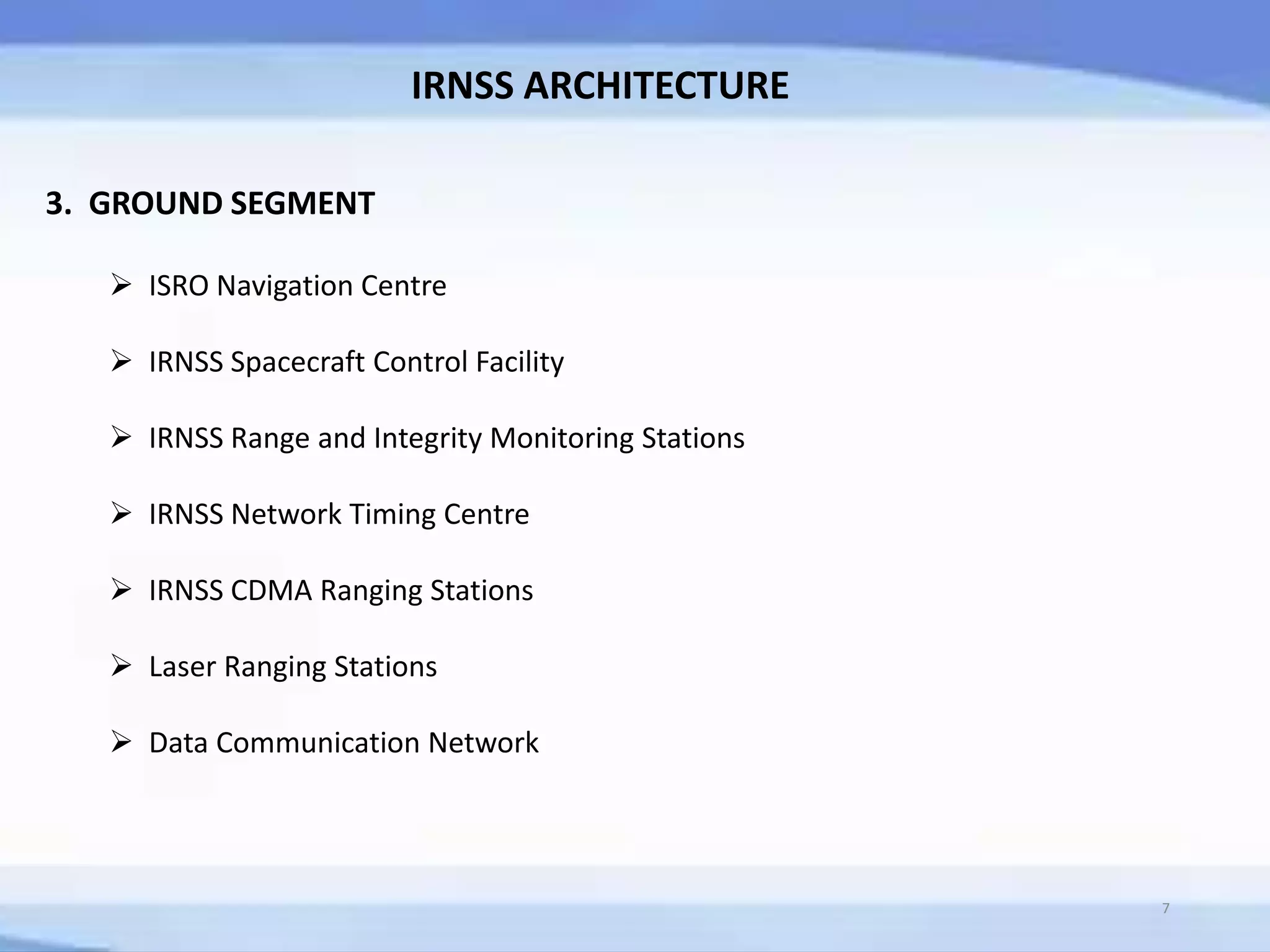
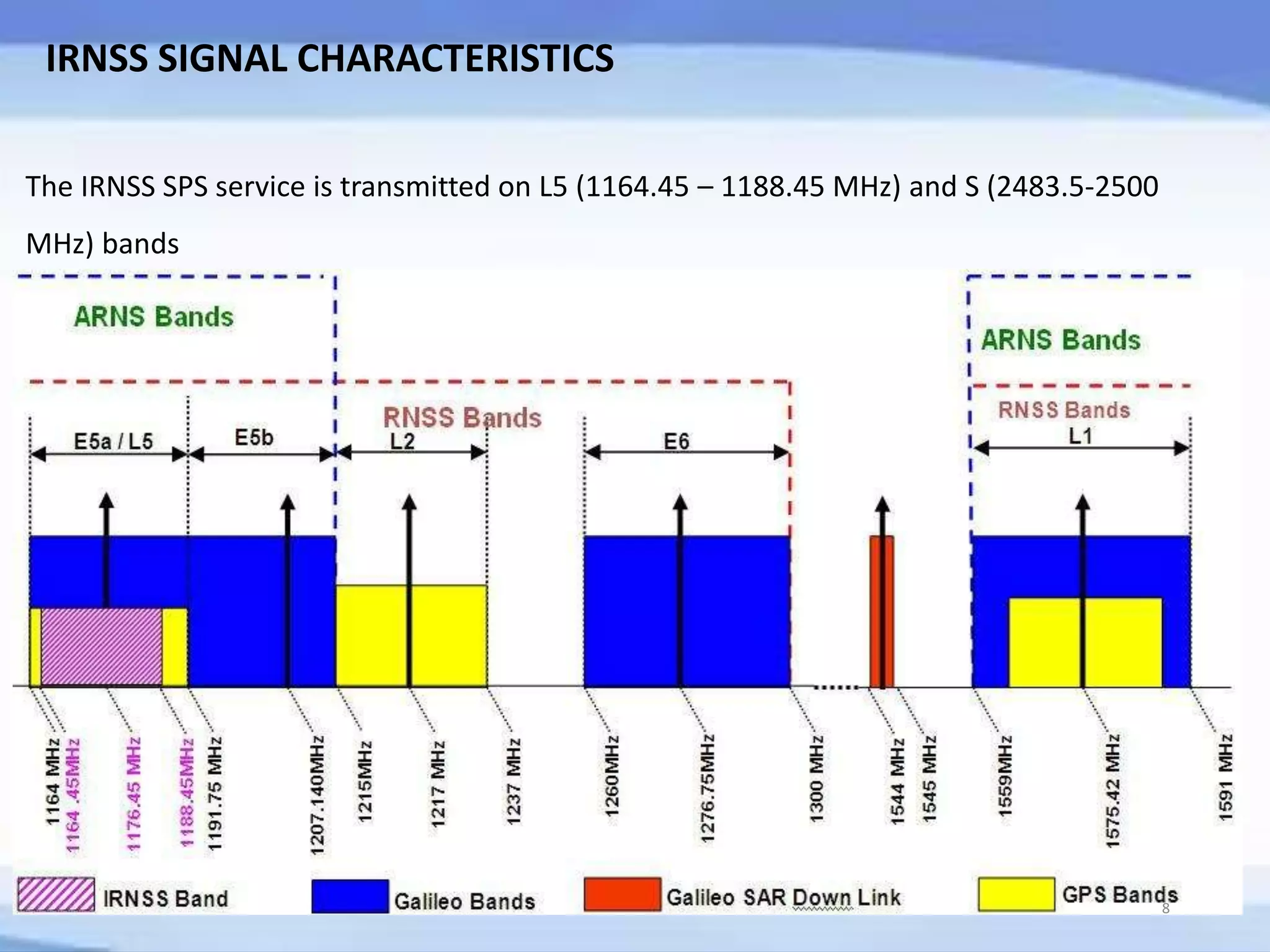
1. IRNSS architecture includes 7 satellites in geostationary and geosynchronous orbits that provide positioning services to India and surrounding areas. Signals are transmitted on L5 and S bands.
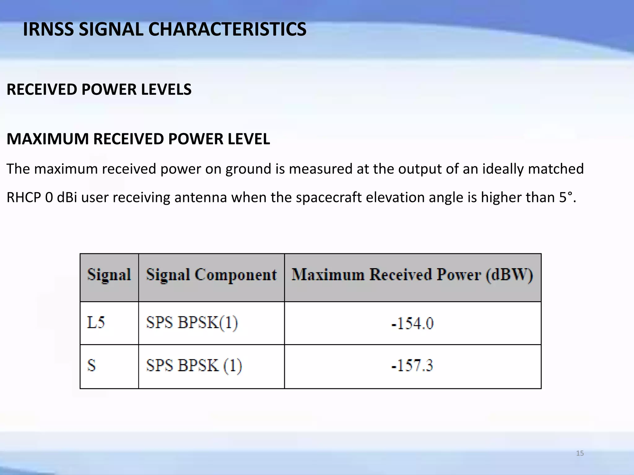
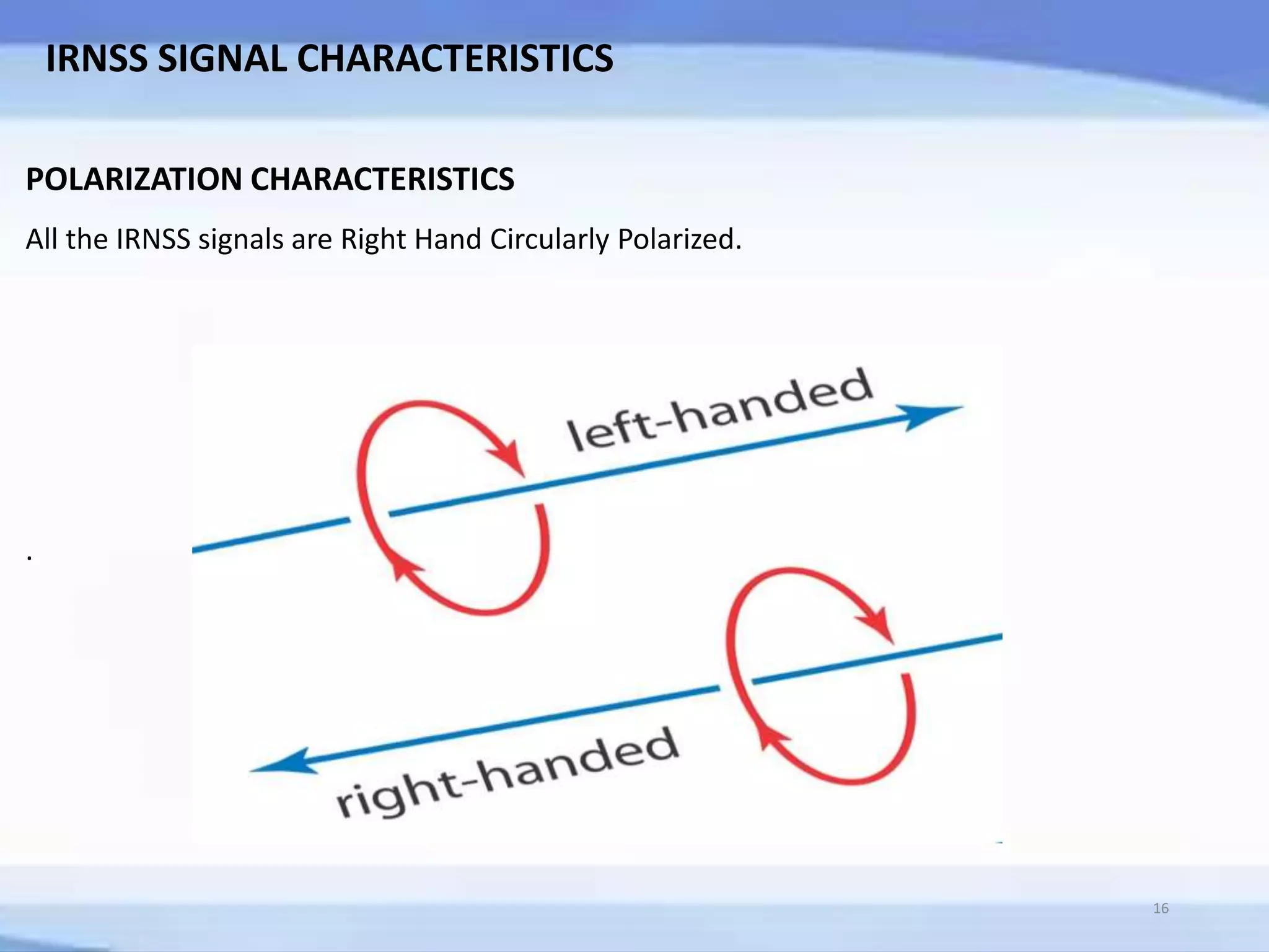
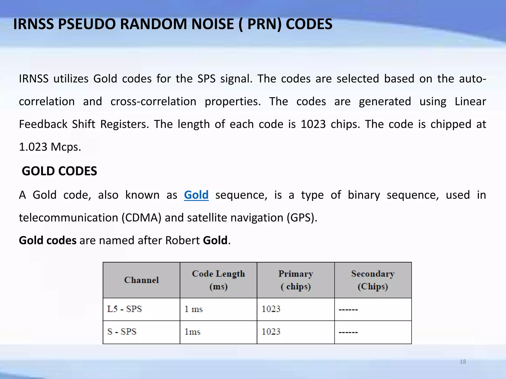
2. IRNSS signals use BPSK modulation and gold codes. Navigation data is transmitted at 50 symbols per second. Precise timing and positioning data is provided for users.
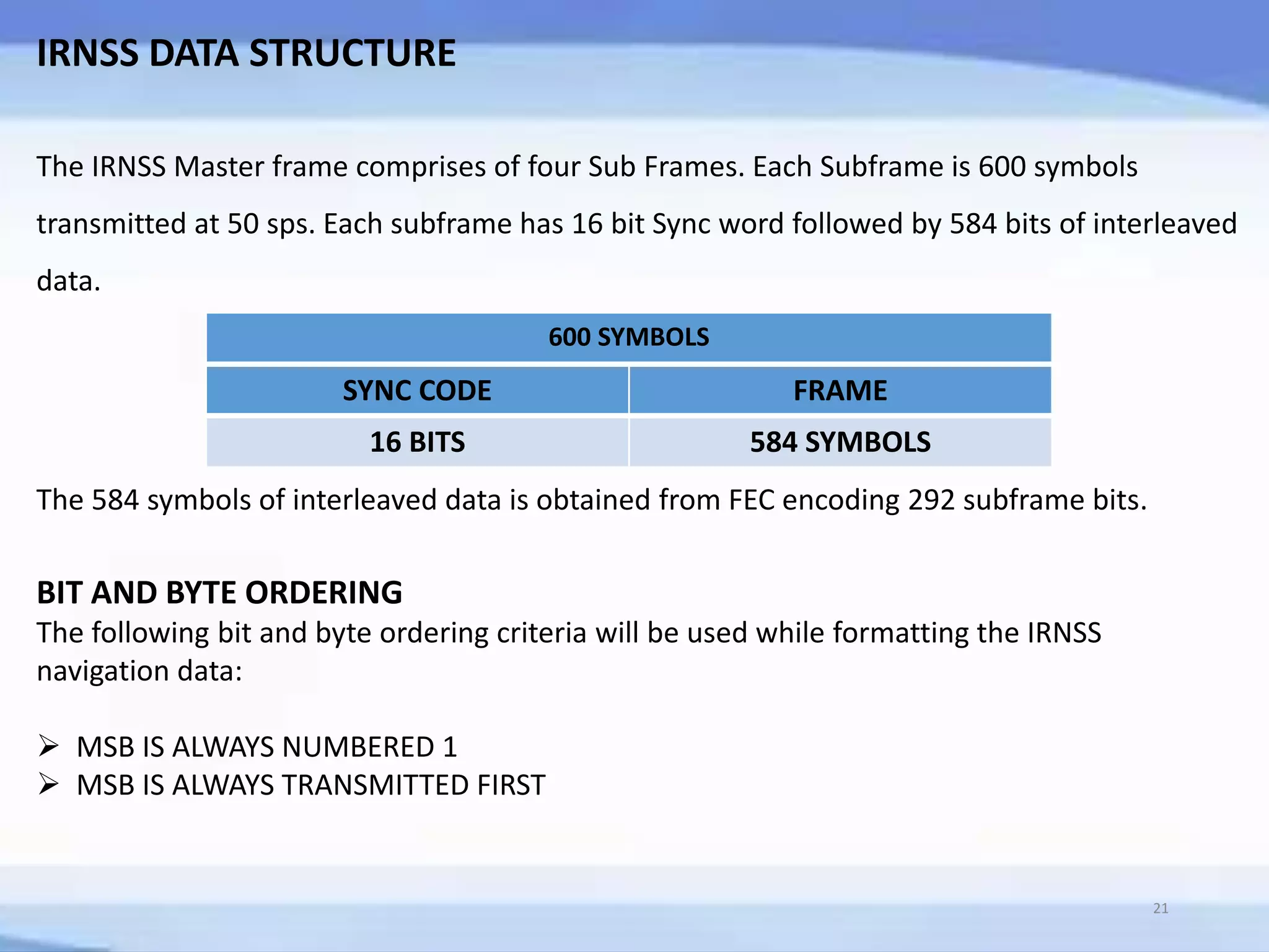
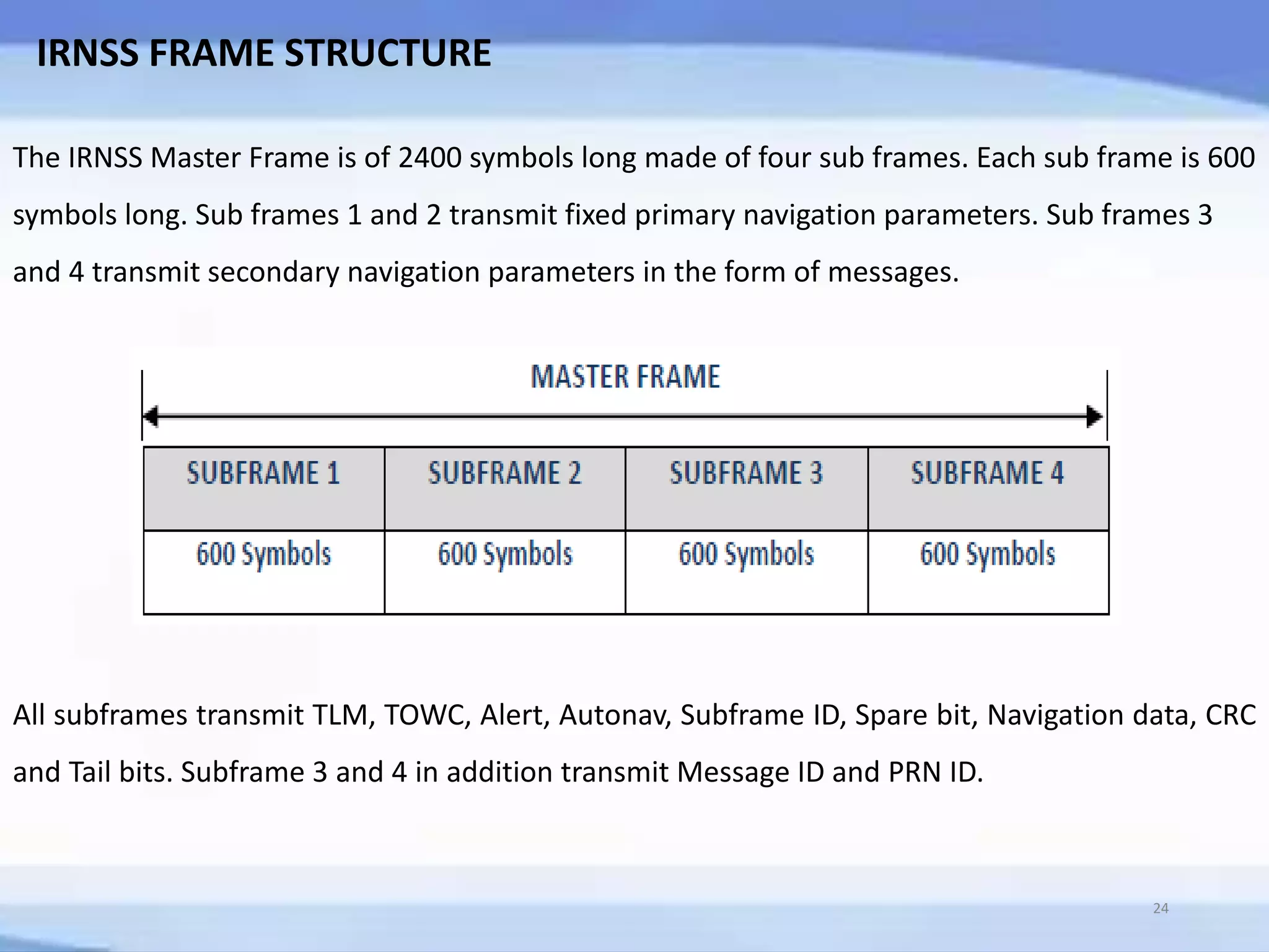
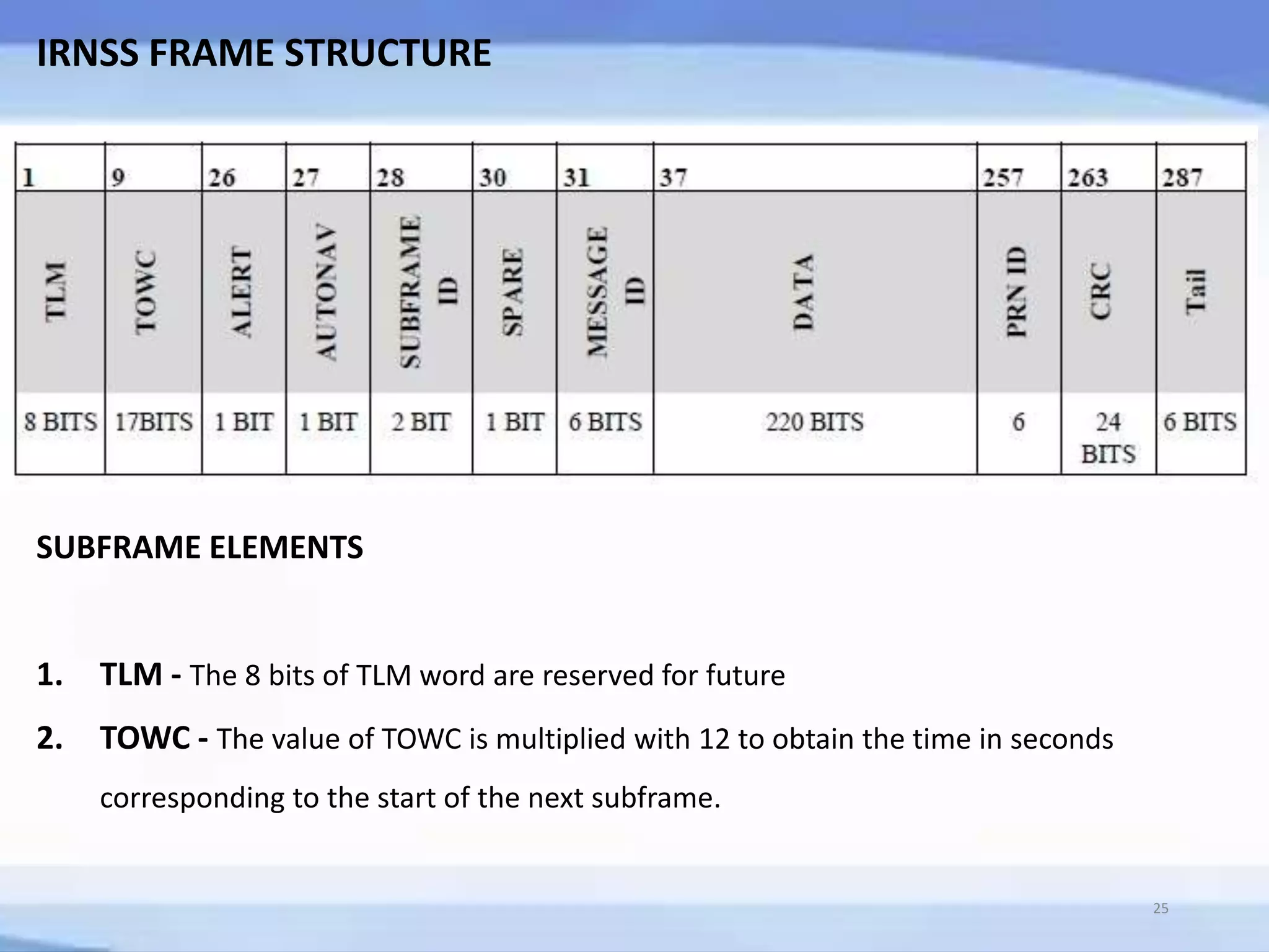
3. IRNSS frames have a master frame structure consisting of 4 subframes that transmit navigation parameters and messages for satellite identification and error correction.


![IRNSS DATA STRUCTURE
The Navigation data subframe of 292 bits is rate 1/2 convolution FEC [ FORWARD EROOR
CORRECTION ] ENCODED and clocked at 50 symbols per second.
INTERLEAVE
The 584 symbols of FEC encoded navigation data is interleaved using a block interleaver with n
columns and k rows. Data is written in columns and then, read in rows.
SYNC WORD
The Synchronization pattern for each of the subframe is 16-bit word. The Synchronization word
is not encoded. The synchronization pattern allows the receiver to achieve synchronization to
the subframe. The Sync pattern is EB90 Hex.
22](https://image.slidesharecdn.com/irnsstechsem-160517131535/75/IRNSS-22-2048.jpg)
![IRNSS DATA STRUCTURE
DATA CONTENTS
WEEK NUMBER - The Week Number is an integer counter that gives the sequential
week number from the origin of the IRNSS time. IRNSS Time is the reference time
generated by IRNWT located at INC. This parameter is coded in 10 bits which covers 1024
weeks (about 19 years).
CLOCK PARAMETERS - The clock coefficients transmitted as part of subframe 1 are
used for IRNSS time and clock corrections. These estimated corrections account for the
deterministic Satellite clock error having characteristics of bias, drift and aging.
ISSUE OF DATA EPHEMERIS AND CLOCK [IODEC] - For IRNSS satellites, the IODEC is a
8-bit number which indicates the issue number of the data set and thereby provides the
user with a convenient means of detecting any change in the ephemeris and clock
parameters.
23](https://image.slidesharecdn.com/irnsstechsem-160517131535/75/IRNSS-23-2048.jpg)


![33
REFERENCES
[1] INDIAN REGIONAL NAVIGATIONAL SATELLITE SYSTEM SIGNAL IN SPACE ICD FOR STANDARD
POSITIONING SYSTEM VERSION 1.0 – ISRO- June 2014.
[2] Analysis of IRNSS over Indian Subcontinent Vyasaraj Guru Rao1, Gérard Lachapelle1, Vijay Kumar
SB21Position, Location And Navigation (PLAN) Group, Department of Geomatics Engineering University of
Calgary 2Accord Software & Systems Pvt. Ltd. Bangalore, India. http://plan.geomatics.ucalgary.ca
[3] Indian Regional Navigation Satellite system signal in space ICD,Nov 2009, ISRO-ISAC-IRNSS-SPS-RS/1.0,
2009.
[4] Global positioning system: Theory and applications. Bradford W.Parkinson, James J. Spilker Jr. (Ch: 18)
[5] Relativity and the Global Positioning System, Neil Ashby.](https://image.slidesharecdn.com/irnsstechsem-160517131535/75/IRNSS-33-2048.jpg)
![34
REFERENCES
[6] IRNSS-1/B/C Retroreflector Array Characteristics;
http://ilrs.gsfc.nasa.gov/missions/satellite_missions/current_missions/irna_reflector.html.
[7] Thoelert S., Montenbruck O., Meurer M. (2014)“IRNSS-1A: signal and clock characterization of the
Indian regional navigation system”, GPS Solutions 18(1):147-152, DOI 10.1007/s1029013-0351-7.
[8] Pearlman M.R., Degnan J.J., Bosworth J.M. (2002)“The International Laser Ranging Service”, Advances
inSpace Research 30(2):135-143, DOI 10.1016/S0273-1177(02)00277-6.
[9] Springer T., Beutler G., Rothacher M. (1999) “Anew solar radiation pressure model for GPS
satellites”,GPS Solutions 2(3):50–62.
[10] Montenbruck O. Steigenberger P., Hauschild A.(2014) “Broadcast versus Precise Ephemerides: a
Multi-GNSS Perspective”, GPS Solutions, DOI 10.1007/s10291-014-0390-8.](https://image.slidesharecdn.com/irnsstechsem-160517131535/75/IRNSS-34-2048.jpg)


![Seller Deck - Presentation [Concert L2].PPTX](https://cdn.slidesharecdn.com/ss_thumbnails/sellerdeck-presentationconcertl2-251219171156-24982daf-thumbnail.jpg?width=640&height=640&fit=bounds)


