Download to read offline
![INTERNATIONAL RESEARCH JOURNAL OF ENGINEERING AND TECHNOLOGY (IRJET) E-ISSN: 2395-0056
VOLUME: 08 ISSUE: 01 | JAN 2021 WWW.IRJET.NET P-ISSN: 2395-0072
© 2021, IRJET | Impact Factor value: 7.529 | ISO 9001:2008 Certified Journal | Page 34
DFIG Control Design for Preventing SSR Mode
Deodatta Y. Shingare1, Dr. Sunil Kumar T. K.2
1Research Scholar, Dept. of Electrical Engineering, National Institute of Technology, Calicut, India
2Assistant Professor, Dept. of Electrical Engineering, National Institute of Technology, Calicut, India
-----------------------------------------------------------------------------***----------------------------------------------------------------------------
Abstract - This paper presents novel approach to design the
controller for Doubly-fed induction generator (DFIG) in
Stator-Voltage-oriented (SVO) synchronous reference frame
for preventing sub-synchronous resonance. The state-space
model of DFIG including inner current closed loop dynamics
with different feed-forward compensation schemes is
developed. The inner current loop dynamics is usually
ignored when SVO control is employed. The effect of inner
current loop dynamics on the sub-synchronous resonance
(SSR) mode of the system is illustrated through analysis and
simulation. The analysis makes it clear that the stability of
DFIG and also the SSR mode excitation in SVO depends
mainly on the tuning of the proportional-integral (PI)
controllers. Erroneous tuning results into instability and also
excitation of SSR mode. This paper contributes the tuning
methodology of the PI-controllers in order to secure the
stability of DFIG and also the additional advantage of
preventing SSR mode under SVO vector control scheme.
Key Words: doubly-fed induction generator (DFIG);
stator-voltage-oriented (SVO) vector control;
proportional-integral (PI) controller, sub-synchronous
resonance (SSR) mode, feed-forward compensation
1. INTRODUCTION
The most preferred topology for high power (+5 MW)
wind applications and currently very popular is Doubly-fed
induction generator (DFIG). Its independent active and
reactive power control along with variable-speed
operation offer many advantages over other fixed-speed
topologies [1]. Commercially important advantages of
employing DFIG in wind power applications include lower
power rating of power electronic interface and ultimately
the lower cost. Depending on the orientation of the
synchronously rotating dq0 reference frame [2], vector
control schemes employed for DFIG are: (1) stator flux
orientation (SFO) – d-axis aligned to stator flux vector and
(2) stator voltage orientation (SVO) – q-axis aligned to
stator voltage vector.
The reactive power production of the DFIG limits the
stability [3], when SFO is employed. However, when SVO is
employed, such stability problems do not exist [4]. In the
analysis of these schemes, it is considered that the rotor
current tracks its reference perfectly, ignoring the effect of
controller tuning on the stability of DFIG. The dynamics of
inner current loop is taken into account in stability
analysis of SFO based various implementations of the
vector control schemes in [5].
In this paper the inner current loop dynamics are taken
into account and the impact of the tuning of PI controllers
on the stability of DFIG and SSR mode in SVO is
investigated. Pole-assignment technique is followed for
controller design. Both the mathematical analysis and
simulations reveal that the erroneous tuning of the PI
controllers lead to the unstable operation of DFIG and/or
can also lead to SSR mode excitation in SVO vector control.
The paper is organized as follows: Section II includes the
mathematical model of DFIG. The pole-assignment design
strategy is detailed in Section III. The state-space model of
DFIG system in SVO is presented in Section IV. The stability
analysis of DFIG in SVO is carried out in Section V.
Simulation evaluation is presented in Section VI and finally
the conclusion in Section VII.
2. MATHEMATICAL MODEL OF DFIG SYSTEM
2.1 Park-model of DFIG
The T-equivalent circuit representing the Park Model [6] of
DFIG in synchronous reference frame, is shown in Fig.1.
Based on the T-equivalent circuit, the mathematical model
of DFIG system in per unit of system base is represented as
DFIG equations in synchronously rotating d-q reference
frame:
(1)
(2)
(3)
(4)
(5)
(6)
Fig.1 Park Model (T-equivalent circuit) of DFIG in
synchronous reference frame](https://image.slidesharecdn.com/irjet-v8i108-210518101729/75/IRJET-DFIG-Control-Design-for-Preventing-SSR-Mode-1-2048.jpg)
![INTERNATIONAL RESEARCH JOURNAL OF ENGINEERING AND TECHNOLOGY (IRJET) E-ISSN: 2395-0056
VOLUME: 08 ISSUE: 01 | JAN 2021 WWW.IRJET.NET P-ISSN: 2395-0072
© 2021, IRJET | Impact Factor value: 7.529 | ISO 9001:2008 Certified Journal | Page 35
(7)
(8)
(9)
(10)
where,
̅ : Stator voltage space vector
̅ : Rotor voltage space vector referred to
stator
̅ : Stator current space vector
̅ : Rotor current space vector referred to
stator
̅
̅
̅
̅ : Stator flux-linkage space vector (11)
̅̅̅ : Rotor flux-linkage space vector referred
to stator (12)
: Stator and rotor resistance referred to stator
: Stator and rotor leakage inductance referred to
stator,
: Magnetizing inductance referred to stator,
2.2 RSC Inner Rotor Current Control Loop
Eliminating the stator current and rotor flux linkages from
the stator and rotor voltage equations, finally we get the
rotor voltage as balance of emfs in the rotor circuit, which
is used to derive the rotor current control law.
̅ ̅ ̅ ̅ ̅ ̅ (13)
Thus the rotor voltage equation includes:
The rotor voltage injection: ̅
A voltage drop across the rotor resistance
̅
A cross-coupling induced emf term
̅
An induced emf term associated with stator flux
̅
An induced emf term associated with stator transients
̅ ( ) ( )
An induced emf term in the Thevenin’s equivalent
inductance (as seen from the rotor with stator short
circuited):
̅ ( )
Laplace transform of equation (13) and subsequent
simplification yields,
[ ]
[ ( ) ]
(14)
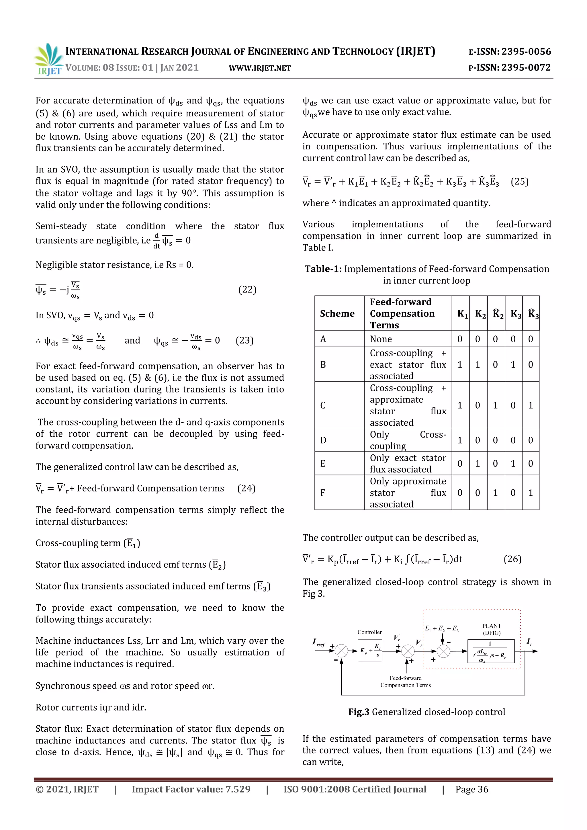
The equation (14) represents the process or plant, how the
injected voltage Vr in rotor circuit causes the current Ir.
The block diagram of plant is shown in Fig.2. The plant or
process can be represented by,
[ ( ) ]
(15)
r
b
rr
R
s
)
L
(
1
3
2
1 E
E
E
PLANT
(DFIG)
+
-
r
V r
I
The terms E1, E2 and E3 represent the internal
disturbances of the plant. From the stator flux-linkage
equations (5) & (6), the stator currents can be expressed
as:
(16)
(17)
Substituting these stator currents into stator voltage
equations (1) & (2) yields,
(18)
(19)
The equations (18) & (19) show that the stator flux and its
transients are function of both stator voltage and rotor
current, thus the terms E1, E2 and E3 depending on the
rotor current and stator flux are the internal disturbances.
For compensation of stator flux transient terms, the
following equations, derived from equations (18) & (19),
are used:
(20)
(21)
Fig.2 Block diagram of Plant (Open loop system)](https://image.slidesharecdn.com/irjet-v8i108-210518101729/75/IRJET-DFIG-Control-Design-for-Preventing-SSR-Mode-2-2048.jpg)
![INTERNATIONAL RESEARCH JOURNAL OF ENGINEERING AND TECHNOLOGY (IRJET) E-ISSN: 2395-0056
VOLUME: 08 ISSUE: 01 | JAN 2021 WWW.IRJET.NET P-ISSN: 2395-0072
© 2021, IRJET | Impact Factor value: 7.529 | ISO 9001:2008 Certified Journal | Page 37
̅ ̅ ̅ (27)
The transfer function between and is,
[ ( ) ]
(28)
Assuming that the feed-forward compensation nullifies
the effect of disturbances, we have .
The controller can be designed considering the process
model as,
[ ( ) ]
( )
* ( ) +
(29)
2.3 RSC Outer-loop Control Design:
2.3.1 Speed Control Loop:
Speed control of DFIG is essential for MPPT operation. The
inner current control loop dynamics is very fast as
compared to that of the outer speed control loop. Hence,
the effect of inner loop is ignored. The design technique is
same as that used for inner current control loop. In SVO,
electromagnetic torque is controlled by q-axis rotor
current
( ) (30)
The q-axis rotor current can control speed independently.
Transfer function between speed and q-axis rotor current
is given by:
[ ] (31)
Outer-loop
Controller
s
K
K io
po
-
+ + qr
I
rref
PLANT
2
s
K
K i
p PLANT
1
r
qrref
I
qr
V
Inner-loop
Controller
-
2.3.2 Reactive Power Control Loop:
Reactive Power control of DFIG is essential for maintaining
the power factor. The inner current control loop dynamics
is very fast as compared to that of the outer reactive power
control loop. Hence, the effect of inner loop is ignored. The
design technique is same as that used for inner current
control loop.
In SVO, Reactive Power is controlled by d-axis rotor
current
( ) ( ) (32)
The first term is constant under normal condition and
treated as disturbance.
Transfer function between Reactive power and rotor
current is given by:
* + (33)
Outer-loop
Controller
s
K
K io
po
-
+ + dr
I
sref
Q
PLANT
2
s
K
K i
p PLANT
1
s
Q
drref
I
dr
V
Inner-loop
Controller
-
3. PI-CONTROLLER DESIGN BASED ON POLE-
ASSIGNMENT TECHNIQUE
3.1 Pole-assignment design strategy:
The PI controller transfer function is expressed as,
* + (34)
The plant transfer function is,
( )
* ( ) +
(35)
The closed-loop transfer function T(s) is given by,
(36)
The characteristic equation is,
( )
( )
To determine the controller gains, the characteristic
equation is set to its standard form, .
The PI controller gains are:
and (37)
3.2 Selection of and
Actual system transfer function can be expressed as,
(38)
Fig. 4 Speed Control Loop
Fig. 5 Reactive Power Control Loop](https://image.slidesharecdn.com/irjet-v8i108-210518101729/75/IRJET-DFIG-Control-Design-for-Preventing-SSR-Mode-4-2048.jpg)
![INTERNATIONAL RESEARCH JOURNAL OF ENGINEERING AND TECHNOLOGY (IRJET) E-ISSN: 2395-0056
VOLUME: 08 ISSUE: 01 | JAN 2021 WWW.IRJET.NET P-ISSN: 2395-0072
© 2021, IRJET | Impact Factor value: 7.529 | ISO 9001:2008 Certified Journal | Page 38
Desired transfer function in standard form,
With known ‘a’ and ‘b’, if attempt is made to select and
n such that (2 n = a) making actual transfer function
same as desired one, the proportional gain becomes zero.
Therefore, this combination of and n is avoided.
Usually the damping coefficient is often chosen as 1 or
0.707 in practice. Therefore, with =0.707, the n is so
selected that the closed loop poles lie in the left-half of s-
plane, leading to system stability. Larger the n, wider is
the closed-loop bandwidth and faster is the system
response. The Bandwidth of the inner current loop
dynamics is considered as the tuning parameter for PI
controllers.
Here reduced order (first-order) model is used. Actually
system is complex (higher-order), so while selecting n, its
effect on closed-loop dominant poles is considered and
that n is selected which results in dominant closed-loop
poles sufficiently away from the imaginary axis in left-half
of s-plane.
It is also useful to choose n relative to the bandwidth of
the open-loop system * +. Here, a normalized
parameter 01 is proposed to be used where the desired
closed-loop bandwidth is calculated as:
* + (39)
The parameter is often selected around 0.9 to give a
satisfactory performance.
4. STATE-SPACE MODEL OF DFIG SYSTEM IN SVO
By eliminating the stator and rotor fluxes in equations (1)
to (8), the open-loop state-space model of DFIG is obtained
as,
[ ] [ ]
[ ] (40)
Referring to equations (24) & (25), taking into account the
feed-forward compensation terms of the control law, the
open-loop state-space model can be modified to
[ ] [ ]
[ ] (41)
The state-space model of closed-loop DFIG system is
derived by substituting and from equation (26)
into equation (41) with
∫( ) (42)
∫ (43)
[ ] [ ]
[ ] (44)
The system has six state variables, hence has six poles,
which are obtained from the eigenvalues of the system
matrix . For the DFIG parameters mentioned in Table II,
the bandwidth is selected and controller gains are
computed from equation (37).
For different compensation schemes, the closed-loop poles
of the system are determined and found that the system
has two very lightly damped poles close to the imaginary
axis in s-plane. These are the critical poles that decide the
stability of the system.
Table–2: DFIG parameters
Parameter Value
Paramete
rs
Value
Power
Rating
2 MVA
0.09231
pu
Line
Voltage
690 V
0.09955
pu
Frequency 50 Hz
3.95279
pu
0.00488
pu
4.0451 pu
0.00549
pu
4.0523 pu
5. STABILITY ANALYSIS OF DFIG IN SVO
Here the bandwidth (n) of the inner current loop
dynamics is considered as the tuning parameter of the PI
controllers. In this section, the impact of the bandwidth on
the stability and SSR mode of the system is investigated. If
the real part of the critical poles becomes positive, the
system becomes unstable. The damping ratio (ζ) of the
conjugate pair of the critical poles is observed as the
measure of the stability. The zero damping ratio or negative
value refers to the instability. The eigenvalue analysis is
carried out for all feed-forward compensation schemes by
varying the speed of DFIG in the range 0.7 pu to 1.2 pu. The
observations are as follows:](https://image.slidesharecdn.com/irjet-v8i108-210518101729/75/IRJET-DFIG-Control-Design-for-Preventing-SSR-Mode-5-2048.jpg)
![INTERNATIONAL RESEARCH JOURNAL OF ENGINEERING AND TECHNOLOGY (IRJET) E-ISSN: 2395-0056
VOLUME: 08 ISSUE: 01 | JAN 2021 WWW.IRJET.NET P-ISSN: 2395-0072
© 2021, IRJET | Impact Factor value: 7.529 | ISO 9001:2008 Certified Journal | Page 41
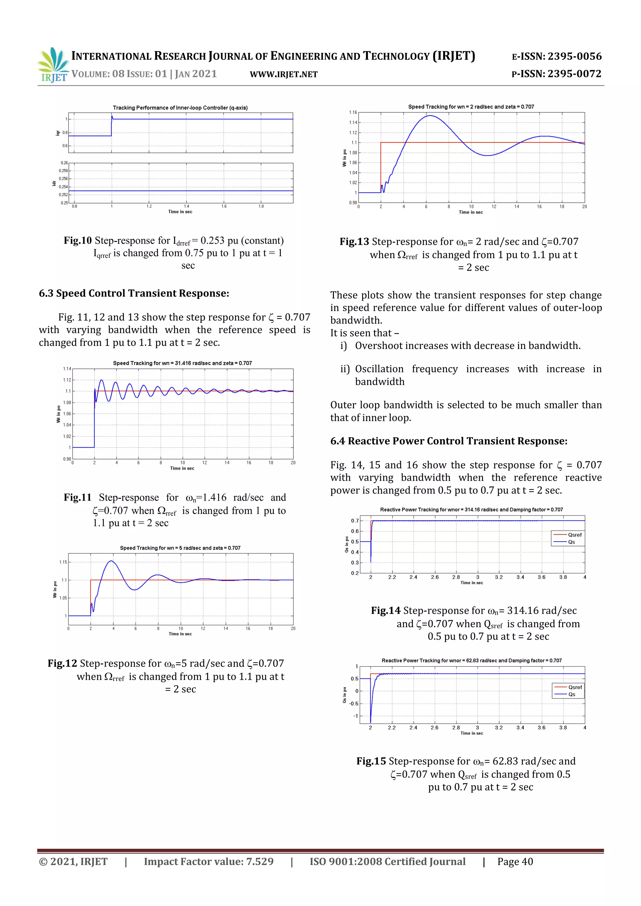
These plots show the transient response for step change in
reactive power reference value for different outer-loop
bandwidths. For lower bandwidth, much higher negative
pulse is observed. Therefore comparatiely higher
bandwidth is preferred.
The theoretical analysis is supported through simulations
in Matlab/Simulink. Thus the stability is accessed under a
small perturbation, which is the change in the reference
signal command. The instability of the inner current loop is
caused when the bandwidth is wrongly selected which
move the critical poles to the unstable region.
7. CONCLUSIONS
i) In SVO, independent control of speed and reactive
power is possible using q-axis and d-axis rotor current
control respectively employing decoupled control.
ii) For Inner-loop fast current control, higher bandwidth
is preferred to avoid the sub-synchronous oscillations
and for outer loop comparatively lower bandwidth is
chosen.
iii) While selecting bandwidth, the eigenvalue analysis is
used to identify the range of bandwidths causing sub-
synchronous resonance and oscillations.
iv) The compensation schemes based on approximate
stator flux estimation leads to instability.
v) The compensation scheme based on cross-coupling
and exact stator flux associated terms is found to be
better.
REFERENCES
[1] S. Muller, M. Deicke, R.W. de Doncker: “Doubly fed
induction generator systems for wind turbines”, IEEE
Ind. Appl. Mag., 2002, 8, (3), pp. 26–33
[2] Hopfensperger B., Atkinson D. J., Lakin R. A.: “Stator-
flux oriented control of doubly-fed induction machine
with and without position encoder”, IEE Proc. Electr.
Power Appl., 2007, 147, (4), pp. 241-250.
[3] Liu C., Weng H., Sun X., Li F.: “Research of stability of
double fed induction motor vector control system”,
Proc. Int. Conf. Elect. Machines and Systems 2001, 2,
(2), pp. 1203-1206.
[4] Petersson A., Harnefors L., Thiringer T.: “Comparison
between stator-flux and grid-flux-oriented rotor
current control of doubly-fed induction generators”,
IEEE 35th Annual Power Electronics Specialists Conf.
2004, vol. 1, pp. 482-486.
[5] Petersson A., Harnefors L., Thiringer T.: “Evaluation of
current control methods for wind turbines using
doubly-fed induction machines”, IEEE Trans, Power
Electron. 2005,20,(1), pp. 227-235.
[6] S. Chondrogiannis, M. Barnes: “Stability of doubly-fed
induction generator under SVO vector control”, IET
Renewable Power Generation, 2008, Vol. 2, N0. 3, pp.
170-180.
BIOGRAPHIES
1. Deodatta Y. Shingare, B.E. (Electrical), M. E. (Electrical
Power Systems), is presently persuing Ph. D. at National
Institute of Technology, Calicut, Kerla (India). His
research area includes DFIG-based wind farm control to
provide dynamic support to the grid under contingency
conditions.
2. Dr. Sunil Kumar T. K., B.Tech. (Electrical and
Electronics Engineering), N.S.S College of Engineering,
Palakkad, 1997, M.Tech. ( Power System), N.I.T.
Jamshedpur , Ph.D. I.I.T Kharagpur, is presently Assistant
Professor in the Department of Electrica Engineering,
National Institute of Technology, Calicut, Kerla (India).
His research area includes Model Matching Controller
Design Methods with Applications in Electric Power
Systems.
Fig.16 Step-response for n= 5 rad/sec and
=0.707 when Qsref is changed from 0.5
pu to 0.7 pu at t = 2 sec](https://image.slidesharecdn.com/irjet-v8i108-210518101729/75/IRJET-DFIG-Control-Design-for-Preventing-SSR-Mode-8-2048.jpg)

This document presents a novel approach to designing a controller for a Doubly-Fed Induction Generator (DFIG) using Stator-Voltage-Oriented (SVO) vector control to prevent sub-synchronous resonance (SSR). It develops a state-space model of the DFIG including inner current loop dynamics and different feed-forward compensation schemes. The analysis shows that the stability of the DFIG and excitation of SSR modes depends mainly on the tuning of the proportional-integral controllers. Erroneous tuning can result in instability or SSR excitation. The paper contributes a tuning methodology for the PI controllers to secure stability and prevent SSR under SVO control.