Interferometry For Precision Measurement Peter Langenbeck
Interferometry For Precision Measurement Peter Langenbeck
Interferometry For Precision Measurement Peter Langenbeck
Interferometry For Precision Measurement Peter Langenbeck
Interferometry For Precision Measurement Peter Langenbeck
1.
Interferometry For PrecisionMeasurement Peter
Langenbeck download
https://ebookbell.com/product/interferometry-for-precision-
measurement-peter-langenbeck-4965404
Explore and download more ebooks at ebookbell.com
2.
Here are somerecommended products that we believe you will be
interested in. You can click the link to download.
Precision Interferometry In A New Shape Higherorder Laguerregauss
Modes For Gravitational Wave Detection 1st Edition Paul Fulda Auth
https://ebookbell.com/product/precision-interferometry-in-a-new-shape-
higherorder-laguerregauss-modes-for-gravitational-wave-detection-1st-
edition-paul-fulda-auth-4342450
Optical Interferometry For Biology And Medicine 1st Edition David D
Nolte Auth
https://ebookbell.com/product/optical-interferometry-for-biology-and-
medicine-1st-edition-david-d-nolte-auth-2514774
Insar Principles Guidelines For Sar Interferometry Processing And
Interpretation
https://ebookbell.com/product/insar-principles-guidelines-for-sar-
interferometry-processing-and-interpretation-36904392
Coherent Atomic Manipulation And Cooling Interferometric Laser Cooling
And Composite Pulses For Atom Interferometry 1st Edition Alexander J
Dunning Auth
https://ebookbell.com/product/coherent-atomic-manipulation-and-
cooling-interferometric-laser-cooling-and-composite-pulses-for-atom-
interferometry-1st-edition-alexander-j-dunning-auth-5353968
3.
Optical Cavities ForOptical Atomic Clocks Atom Interferometry And
Gravitationalwave Detection 1st Ed 2019 Miguel Dovale Lvarez
https://ebookbell.com/product/optical-cavities-for-optical-atomic-
clocks-atom-interferometry-and-gravitationalwave-detection-1st-
ed-2019-miguel-dovale-lvarez-10797266
Development And Characterization Of A Dispersionencoded Method For
Lowcoherence Interferometry Christopher Taudt
https://ebookbell.com/product/development-and-characterization-of-a-
dispersionencoded-method-for-lowcoherence-interferometry-christopher-
taudt-37662748
Nulling Interferometers For Spacebased Highcontrast Visible Imaging
And Measurement Of Exoplanetary Environments 1st Edition Brian Hicks
Auth
https://ebookbell.com/product/nulling-interferometers-for-spacebased-
highcontrast-visible-imaging-and-measurement-of-exoplanetary-
environments-1st-edition-brian-hicks-auth-4634788
The Very Large Telescope Interferometer Challenges For The Future 1st
Edition David Mouillet Auth
https://ebookbell.com/product/the-very-large-telescope-interferometer-
challenges-for-the-future-1st-edition-david-mouillet-auth-4626662
Advanced Interferometers And The Search For Gravitational Waves
Lectures From The First Vesf School On Advanced Detectors For
Gravitational Waves 1st Edition Massimo Bassan Eds
https://ebookbell.com/product/advanced-interferometers-and-the-search-
for-gravitational-waves-lectures-from-the-first-vesf-school-on-
advanced-detectors-for-gravitational-waves-1st-edition-massimo-bassan-
eds-4662426
7.
Tutorial Texts Series
.Ocean Sensing and Monitoring: Optics and Other Methods, Weilin Hou, Vol. TT98
. Laser Beam Quality Metrics, T. Sean Ross, Vol. TT96
. Military Displays: Technology and Applications, Daniel D. Desjardins, Vol. TT95
. Interferometry for Precision Measurement, Peter Langenbeck, Vol. TT94
. Aberration Theory Made Simple, Second Edition, Virendra N. Mahajan, Vol. TT93
. Modeling the Imaging Chain of Digital Cameras, Robert D. Fiete, Vol. TT92
. Bioluminescence and Fluorescence for In Vivo Imaging, Lubov Brovko, Vol. TT91
. Polarization of Light with Applications in Optical Fibers, Arun Kumar, Ajoy Ghatak, Vol. TT90
. Digital Fourier Optics: A MATLAB Tutorial, David G. Voeltz, Vol. TT89
. Optical Design of Microscopes, George Seward, Vol. TT88
. Analysis and Evaluation of Sampled Imaging Systems, Richard H. Vollmerhausen, Donald A. Reago,
Ronald Driggers, Vol. TT87
. Nanotechnology: A Crash Course, Raúl J. Martin-Palma and Akhlesh Lakhtakia, Vol. TT86
. Direct Detection LADAR Systems, Richard Richmond, Stephen Cain, Vol. TT85
. Optical Design: Applying the Fundamentals, Max J. Riedl, Vol. TT84
. Infrared Optics and Zoom Lenses, Second Edition, Allen Mann, Vol. TT83
. Optical Engineering Fundamentals, Second Edition, Bruce H. Walker, Vol. TT82
. Fundamentals of Polarimetric Remote Sensing, John Schott, Vol. TT81
. The Design of Plastic Optical Systems, Michael P. Schaub, Vol. TT80
. Fundamentals of Photonics, Chandra Roychoudhuri, Vol. TT79
. Radiation Thermometry: Fundamentals and Applications in the Petrochemical Industry, Peter Saunders,
Vol. TT78
. Matrix Methods for Optical Layout, Gerhard Kloos, Vol. TT77
. Fundamentals of Infrared Detector Materials, Michael A. Kinch, Vol. TT76
. Practical Applications of Infrared Thermal Sensing and Imaging Equipment, Third Edition, Herbert
Kaplan, Vol. TT75
. Bioluminescence for Food and Environmental Microbiological Safety, Lubov Brovko, Vol. TT74
. Introduction to Image Stabilization, Scott W. Teare, Sergio R. Restaino, Vol. TT73
. Logic-based Nonlinear Image Processing, Stephen Marshall, Vol. TT72
. The Physics and Engineering of Solid State Lasers, Yehoshua Kalisky, Vol. TT71
. Thermal Infrared Characterization of Ground Targets and Backgrounds, Second Edition, Pieter A. Jacobs,
Vol. TT70
. Introduction to Confocal Fluorescence Microscopy, Michiel Müller, Vol. TT69
. Artificial Neural Networks: An Introduction, Kevin L. Priddy and Paul E. Keller, Vol. TT68
. Basics of Code Division Multiple Access (CDMA), Raghuveer Rao and Sohail Dianat, Vol. TT67
. Optical Imaging in Projection Microlithography, Alfred Kwok-Kit Wong, Vol. TT66
. Metrics for High-Quality Specular Surfaces, Lionel R. Baker, Vol. TT65
. Field Mathematics for Electromagnetics, Photonics, and Materials Science, Bernard Maxum, Vol. TT64
. High-Fidelity Medical Imaging Displays, Aldo Badano, Michael J. Flynn, and Jerzy Kanicki, Vol. TT63
. Diffractive Optics–Design, Fabrication, and Test, Donald C. O’Shea, Thomas J. Suleski, Alan D.
Kathman, and Dennis W. Prather, Vol. TT62
. Fourier-Transform Spectroscopy Instrumentation Engineering, Vidi Saptari, Vol. TT61
. The Power- and Energy-Handling Capability of Optical Materials, Components, and Systems, Roger M.
Wood, Vol. TT60
. Hands-on Morphological Image Processing, Edward R. Dougherty, Roberto A. Lotufo, Vol. TT59
. Integrated Optomechanical Analysis, Keith B. Doyle, Victor L. Genberg, Gregory J. Michels, Vol. TT58
. Thin-Film Design: Modulated Thickness and Other Stopband Design Methods, Bruce Perilloux, Vol. TT57
. Optische Grundlagen für Infrarotsysteme, Max J. Riedl, Vol. TT56
. An Engineering Introduction to Biotechnology, J. Patrick Fitch, Vol. TT55
(For a complete list of Tutorial Texts, see http://spie.org/tt.)
Introduction to theSeries
Sinceitsinceptionin1989,theTutorialTexts(TT)serieshasgrowntocovermany
diversefields of scienceand engineering.The initialideafor theserieswas tomake
material presented in SPIE short courses available to those who could not attend
and to provide a reference text for those who could. Thus, many of the texts in this
series are generated by augmenting course notes with descriptive text that further
illuminates the subject. In this way, the TT becomes an excellent stand-alone
reference that finds a much wider audience than only short course attendees.
Tutorial Texts have grown in popularity and in the scope of material
covered since 1989. They no longer necessarily stem from short courses;
rather, they are often generated independently by experts in the field. They are
popular because they provide a ready reference to those wishing to learn
about emerging technologies or the latest information within their field. The
topics within the series have grown from the initial areas of geometrical optics,
optical detectors, and image processing to include the emerging fields of
nanotechnology, biomedical optics, fiber optics, and laser technologies.
Authors contributing to the TT series are instructed to provide introductory
material so that those new to the field may use the book as a starting point to
get a basic grasp of the material. It is hoped that some readers may develop
sufficient interest to take a short course by the author or pursue further
research in more advanced books to delve deeper into the subject.
The books in this series are distinguished from other technical
monographs and textbooks in the way in which the material is presented.
In keeping with the tutorial nature of the series, there is an emphasis on the
use of graphical and illustrative material to better elucidate basic and
advanced concepts. There is also heavy use of tabular reference data and
numerous examples to further explain the concepts presented. The publishing
time for the books is kept to a minimum so that the books will be as timely
and up-to-date as possible. Furthermore, these introductory books are
competitively priced compared to more traditional books on the same subject.
When a proposal for a text is received, each proposal is evaluated to
determine the relevance of the proposed topic. This initial reviewing process
has been very helpful to authors in identifying, early in the writing process, the
need for additional material or other changes in approach that would serve to
strengthen the text. Once a manuscript is completed, it is peer reviewed to
ensure that chapters communicate accurately the essential ingredients of the
science and technologies under discussion.
It is my goal to maintain the style and quality of books in the series and to
further expand the topic areas to include new emerging fields as they become
of interest to our reading audience.
James A. Harrington
Rutgers University
12.
Contents
Preface xiii
1 KnownMethods: An Assessment of the State of the Art—Newton and Fizeau 1
1.1 Introduction 1
1.2 Limited Use of Newton’s Method 8
1.3 Other Methods of Interferometry 9
1.3.1 Tolansky: one experimenter’s indispensable knowledge 15
1.4 Desirable Features for Safe, Applicable, and Economic Interferometry 16
1.4.1 Commercial coherent white light 16
1.4.2 Light sources for increased distance from reference to sample 17
1.5 The Often-Neglected Angle of Light Incident to the Work 19
1.5.1 Selecting only one angle of incidence 20
1.5.2 Instrumental consequences 23
1.5.3 The multifunctionality of a prism’s hypotenuse: beamsplitter,
reference, and obliqueness provider 24
1.6 Knowing the Angle of Incidence with Respect to the Fringe Equivalent 26
1.6.1 When the angle of total internal reflection is zero 26
1.6.2 Calibration masters 27
1.6.3 Are 5-μm fringes meaningful? 29
1.6.4 Two-beam and multiple-beam walkoff 32
1.6.5 Stray light need not be annoying 33
1.6.6 The scatter flat test 35
References 36
2 From Extended Light Source to Collimated Illumination 39
2.1 Introduction 39
2.2 Technical Relevance of Oblique Incidence 42
2.3 Fast Adjustment of Tilt and Height 45
2.3.1 Autoleveling with mechanical truing 45
2.3.2 Autoleveling with optical position sensing 47
2.4 Variable-Angle u on Samples with Strong Slopes 47
2.5 Interference Contrast 48
2.5.1 Contrast of Fizeau fringes determined by reflectances 50
vii
13.
2.6 Notes onRecording Fringes 52
References 53
3 Interference Visualized by Vector Diagrams 55
3.1 Vectorial Representation of Dual- and Multiple-Beam Interference 55
3.2 The Airy Case: Zero Wedge Angle 57
3.3 The Fizeau Case 58
3.4 The Function of the Zeroth-Order Beam E0 60
3.5 Advantages and Disadvantages of Using Multiple-Beam Interferometry 65
3.6 An Application: Evaluating the Task of Nulling 65
3.6.1 An artifact for nulling (autocollimation) and scanning 67
3.7 Other Forms of Pointing Interferometry
with Respect to Nulling 70
3.8 Fizeau Interferometers with Large Cavities 71
3.9 Stringent Requirements for Collimation 72
3.10 Acceptable Uniformity of Illumination 74
References 75
4 Optical Laboratory Equipment 77
4.1 Experimenting with Collimation: Autocollimation 77
4.1.1 Autocollimation: The key to any interferometer 79
4.1.2 The autocollimator 80
4.2 Fizeau Interference and Autocollimation 80
4.2.1 Common applications of autocollimation 80
4.2.2 Orthogonality of two spindle axes 82
4.2.3 Price-worthy Fizeau instrumentation 84
4.2.3.1 Two typical applications of plano-convex
collimating lenses 85
4.3 Testing the Collimation of an Expanded Laser Beam 86
4.3.1 Murty’s parallel shearing plate 86
4.3.2 Variable shear: two parallel plates 89
4.3.3 Variable shear and tilt to suit 89
4.3.4 Double wedge plate shearing interferometer 90
4.3.5 Variable shear and tilt: enhanced sensitivity 91
4.3.6 A useful, robust interferometer 93
References 97
5 Straight Lines and Right Angles 99
5.1 Measuring 90-deg Roof Angles on Mirrors and Prisms 99
5.1.1 Reversion of wavefronts 101
5.1.2 Measuring small angles with straight fringes 103
5.1.3 Enhanced sensitivity for 90-deg-roof-angle quality assurance 104
5.1.4 Plus or minus angular error? High or low on surfaces? 106
5.1.5 Polarization 108
viii Contents
14.
5.2 Function ofthe Trihedral Prism: the Corner Cube Prism (or CCR) 111
5.2.1 Retroreflectors in practice 115
5.2.1.1 Illustrative micromachined retroreflectors 115
5.2.1.2 Calibration of distance change: predominant
application 115
5.2.1.3 Using the CCR’s lateral displacement in linometry 115
5.2.1.4 Comments on CCR displacement applications 117
5.2.1.5 3D metrology with a CCR 120
5.2.1.6 Model of an adjustable CCR for machine tool
alignment 120
5.2.1.7 Measuring tilt motion of one adjustable mirror 122
5.2.1.8 CCR solid-block inverting shear interferometer (ISI) 123
5.2.1.9 Application of a CCR in centration measurement 125
5.2.2 Quality assurance of the CCR 126
5.2.2.1 Summary of sensitivity enhancement by double
pass 130
5.2.2.2 Fringe sharpening? 130
5.2.3 Improving collimation 131
5.2.3.1 A useful “fringe” benefit 136
5.2.3.2 CCR rotation 136
5.2.4 An alternative to the CCR: the ball reflector or “cat’s eye” 137
5.2.4.1 Applications of the SSR 139
5.2.4.2 Integrated-optic distance-measuring interferometer 139
5.2.5 Autocollimation test for equality of radii of curvature 140
5.2.6 Separating angular errors from flatness errors on cubes and
90-deg prisms 141
5.2.7 Measuring the parallelism of transparent laser rods 144
5.2.8 90-deg angular calibration cubes 146
References 147
6 Polygons 149
6.1 Polygon Mirror Wheels 149
6.1.1 Preparing and verifying axial surfaces of polygons 152
6.1.2 Verifying facet flatness and angles 154
6.1.3 Polygon rotation in 0.1-arcsec steps 157
6.1.4 Polygon’s relative pyramidal error (static) 157
6.2 Angular Standards Calibrated by Interferometry 159
6.2.1 0.1-arcsec resolution within ±15 deg 160
6.2.2 Arcsecond rotation 161
References 161
7 Optical Shop Daily Tasks 163
7.1 Centration in the Optical Shop 163
7.1.1 General-utility centering metrology 163
ix
Contents
15.
7.2 Optical Work163
7.3 Centering a Spherical Generator 165
7.3.1 Finding the turning center experimentally 166
7.4 Attributes of Centering: State of the Art 167
7.5 Can the Centering Procedure Be Made Less Laborious? 168
7.5.1 Alternative solutions 168
7.5.2 Rotating the optical beam instead of the sample 168
7.5.3 Centering interferometry 170
7.5.4 Enhanced sensitivity 172
7.5.5 Fine control by the naked eye 173
7.5.6 Further increasing centration sensitivity 174
7.5.7 Conventional hardware for centration (air-bearing spindles) 176
7.5.8 Centration without rotating the lens 177
7.6 Homogeneity 178
7.6.1 Methods for error separation 178
7.6.2 Fast qualitative assessment of homogeneity 184
References 185
8 Mass-Produced Specular Surfaces 187
8.1 Specular Surfaces That Are Grossly Unflat 187
8.1.1 Strioscopy: Is it quantitative? 190
8.1.2 Further review of strioscopy 191
8.1.3 Interference in strioscopy: the origin of coherent background
(reference) 193
8.1.4 Mechanical focal-plane interaction 196
8.1.5 Optical interaction: color coding 197
8.1.5.1 Further comments on striograms 199
8.2 The One-Arm Interferometer 200
8.2.1 Comments on the one-arm interferometer 204
8.2.2 Removing the spatial carrier frequency 204
8.2.2.1 Summary 205
8.2.3 Other interactions in the defocal plane 205
References 206
9 Nonspecular, Near-Flat, Mass-Produced Surfaces 207
9.1 Degenerate One-Arm Interferometer: The Lloyd Interferometer 207
9.1.1 Higher-order Lloyd interferometer 210
9.1.2 Alignment and interpretation 211
9.1.3 Reduced interferometric sensitivity allows for broader
adaptation 214
9.1.4 Lloyd interferometer for dynamic testing 214
9.1.5 Measuring the flatness of lapped granite plates/machine beds 216
9.1.6 High or low? 219
9.1.7 Summary of Lloyd interferometry 219
x Contents
16.
9.2 Instrumentation forGrazing Incidence Interferometry 220
9.2.1 The prism interferometer 224
9.2.2 The image in a prism interferometer 225
9.2.3 Parameters influencing DP/P reading accuracy 227
References 228
10 Enhancing Regular Interferometric Sensitivity 229
10.1 Multiple Reflections 229
10.2 Advantages and Disadvantages of Multipass Interferometers 234
10.3 Relevance of Multiple-Reflection and Off-Axis Illumination 236
10.4 Multipass Applications 236
10.4.1 Multipass in comparator interferometry 236
10.4.2 Angular metrology 237
Reference 239
Index 241
xi
Contents
18.
Preface
With new materialadded to the English translation of Chapter 7 of the
German Wirtschaftliche Mikrobearbeitung (Carl Hanser Verlag, 2009), the
author presents developments in physical, optical, and mechanical engineering
over the past 60 years. The enduring impetus for this work is owed to the late,
great gentleman engineer, Gordon J. Watt, with his assertion that optical
wavefronts used in interferometers are complementary to the surfaces used to
build air bearings. A foremost example of this statement is the fact that a
plano-convex lens is confined by surfaces that are equivalent to those defining
the Watt air-bearing spindle. The spindle rotor consists of a truncated
hemisphere, rigidly connected to a flat disk.
Soon after the author founded Intop Entwicklungen (Baden-Württemberg,
Germany) in 1972, he and G. J. Watt witnessed a sudden growth in spindle-
enabling applications and new machines whose performance relied
completely on low-axial-error motion (less than 5 nm) and an angular error
motion of less than 0.1 arcsec. The bearing’s disk took on multiple integral
functions: as a polygon wheel, as a polishing scaife for diamond tools, and as
a chuck for thin substrates (memory substrates with memory scaling of 14.5).
Interferometers for in-process quality control and final acceptance needed to
be developed.
Increased interferometric sensitivity by multiple passes was adopted as a
technique for measuring small departures from 90 deg, both for the metrology
of corner cubes and for extremely sensitive tilt measurement (one of the three
CCR mirrors being the front mirror on a problem spindle’s nose).
Interferometric techniques that facilitated the assembly of ultraprecision
machining and metrology machines (3D orthogonal) were developed.
Likewise, decreasing interferometric sensitivity made possible the inspec-
tion of nonspecular surfaces. The cost for quality control of mass-produced
components (for example, water faucet ceramic seals) was substantially
reduced. The inspection technique in use at the time became the standard for
expedient handling of samples with interferometric precision.
This relatively recent development focused on measuring tilt error
motions of air-bearing spindles, as is amply covered in this book. Tasks that
xiii
19.
occur every dayin an optical shop—such as centering and homogeneity
measurement—are also extensively discussed.
The author gladly shares his recollections and experience with students,
scholars, and peers but also wants to give a warning: dealing with optics every
day may turn a profession into an obsession!
The author appreciates SPIE for making this publication possible. He also
expresses his warm thanks to Prof. Hans Tiziani for frequent, critical
discussions.
Peter Langenbeck
May 2014
xiv Preface
20.
Chapter 1
Known Methods:An
Assessment of the State
of the Art—Newton and Fizeau
1.1 Introduction
The subject of this assessment is surfaces whose final production processes
include lapping, polishing, or micromachining. The majority of these
processes relate to optical components, and many of them carry optical
specifications for mechanical applications such as air-bearing techniques.
Measuring departures from flatness is a common denominator. A useful
compendium of interferometric techniques and applications was assembled
by D. Malacara, A. Cornejo, and A. V. R. K. Murty.1
One of the procedures involved in the practice of an optician is illustrated in
Fig. 1.1: an optical glass, the reference, is placed onto the semifinished work.
The reference is illuminated by a spectral lamp l behind an extended diffusing
screen and is observed. The observer sees a fringe pattern, the interpretation of
which is explained in Fig. 1.2. Actual fringe patterns are shown in Figs. 1.5(a)
and (b), and Fig. 2.1(b). Such patterns appear to be similar to cartographic
contour lines. This assessment procedure, which creates what is known as
Newton’s rings, is as simple to handle as it is to comprehend; it is the last option
using low-cost instrumentation for mechanical/optical metrology with sub-
micrometric resolution before expensive hardware and software need to be
introduced. In that sense, the importance of interferometry to the precision
engineer can be compared to that of a stethoscope to the general medical
practitioner. This is our starting point for the assessment of the fascinating
methods and instruments of interferometry.
The distance t between the reference and the workpiece in Fig. 1.1 is
governed by three factors:
1. the small amount of dust that appears virtually everywhere, even in clean
boxes and in compressed air for air bearings,
1
21.
2. three randomlyoccurring high spots on either one or both bulk surfaces, and
3. dust on the high spots of the surfaces. Most dust particles are compressible,
and some are abrasive. The schematic representation of dust particles in
Fig. 1.3 shows the typical dust that determines that distance t is in the same
range as gaps in air-bearing techniques.
Figure 1.2 Common evaluation instructions for the interference flatness test. Here,
manually symmetrizing pressure leads to closed annular fringes, known as Newton’s rings,
which can be either convex or concave. There would be two rings in the case sketched here.
Rings are stable in the case of a concave sample and rather unstable in the case of a
convex sample with a high spot in center.
Figure 1.1 Assessment of the departure from flatness using Newton’s interference method.
The screen in front of the spectral lamp serves as an extended light source. The flat reference and
the sample rest on each other. u0
is the angle of observation (excidence between the sample’s
normal and the intuitively chosen line of sight), and u is the angle of incidence, where u0
¼ u.
2 Chapter 1
22.
Notes for thepractitioner
1. An effective and inexpensive cleaning of the testplate/workpiece
combination starts with a fine silk paper or an often-washed cotton cloth
mildly pressed between the two and gently pulled out tangentially.
However, this cleaning method can cause wringing.
2. Changing the pressure point from left to right in Fig 1.2 allows one to see
two closed fringes, indicating a spherical surface with a very large radius
of curvature. Figure 1.4 demonstrates the relationship between the
spherical radius r of the cap, represented by fringe diameter d, sag h, and
the wavelength.
In the production of optical lenses with very short radii of curvature, it is
common to use spherical reference glasses, with the same squeezing treatment.
The diameters, the interference rings, and the known wavelength determine
the difference of radii of the cap.
Two closely tangential glass plates illuminated by sodium spectral light
generate fringes like those in Fig. 1.5(a). Under a mild load, the direction and
spacing P of the fringes can be varied prior to hard contact, the latter
prevented by omnipresent dust. Thanks to the dust, for a convenient empirical
interpretation, it is a common practice to squeeze the plates and thereby shift
the fringes to delineate a defect. For visual inspection, the fringes are aligned
either orthogonally or in parallel to the line of sight; five to seven fringes per
diameter is a practical configuration.
Figure 1.3 Omnipresent dust separating the testplate from the workpiece is thick enough
to prevent contacting (wringing) and thin enough to allow scratching. This frequently cited
illustration of unknown origin is entitled “Contamination of optical surfaces.”2
3
Known Methods: An Assessment of the State of the Art—Newton and Fizeau
23.
At this pointeither wringing occurs, or, as fringes are forcefully aligned,
both surfaces become scratched. This is also the case with spherical reference
glasses used in optical production of lenses. Wearing white gloves does not
change the situation. These scratches are subject to rejection of optical
components and are defined by scratch and dig specifications.3
Scratch quality assessment has become a somewhat controversial subject
between users and suppliers. This book contains two sets of specifications for
technical quantity products that include scratch and dig, corner-cube
retroreflectors (CCRs) (Chapter 5), and polygon mirror wheels (Chapter 6).
An informative account of detecting, avoiding, and accepting scratches is
given by J. A. Slater and D. A. Cox in their paper “Scratches: At what price
quality?”4
Figure 1.4 Annular closed fringes permit simple spherometry. T is the reference flat, and M
is the part of the sample with a spherical surface (in many cases).
4 Chapter 1
24.
Measurement of fringespacing P1 (on an object-to-image scale of 1:1 and
in the same dimension as l) provides the included angle a1 ¼ (l/2)/P1, with
l ¼ the wavelength of light used. Above the minute wedge Da on the
workpiece, one sees fringes of a different spacing P2 [as shown in Fig. 1.5(a)]:
(a þ Da) ¼ (l/2)/P2. The wedge angle g on the surface is
g ¼
l
2
1
P1
1
P2
¼ a1
DP
P2
: ð1:1Þ
Narrowing the distance between the reference and the workpiece [Fig. 1.5(a)]
by some load without changing a causes the fringes to “walk” parallel to
themselves until the two surfaces come into contact, usually at the periphery.
The contact zone is characterized by complete darkness and is the hinge or
Figure 1.5(a) l/2 interference fringes in yellow sodium light between two bare glass plate
surfaces separated by omnipresent dust. The areas of almost complete surface contact
appear darker and less dark with increasing gap t.
5
Known Methods: An Assessment of the State of the Art—Newton and Fizeau
25.
apex of theangle wedge a between the plates. This is also the location of the
optical zero, the zeroth order of interference. By narrowing the gap, fringes
walk into the direction “away” from the zeroth order. The reason for the
darkness sloping through a relative maximum in the zone of no gap,
irrespective of contact pressure, is the l/2 phase jump upon reflection at the
glass/air interface. In transmission, contrast is reversed.
Much research has been reported on the gap thickness obtained by joining
slip metallic or ceramic gauges by wringing, a customary practice in
comparator metrology.6
In this field, residual gaps are reported to range
between 0.01 and 0.001 mm. This gap size appears to be sufficient to cause the
phase jump on the inner glass surface (the dark center in Newton’s rings).
The location of the zeroth-order fringe might be on the workpiece or, more
commonly, far outside the workpiece for an unknown number n of orders. All
that one knows is that n increases or decreases in integer numbers. The change
Dt in distance between the test surface and the reference surface from one fringe
to the next is given by
tn tn1 ¼
l
2
: ð1:2Þ
A mercury vapor lamp with distinct and dominant red, green, and blue
spectral lines produces fringes equivalent to the monochromatic sodium
Figure 1.5(b) An acceptance protocol of a 140-mm-diameter Fizeau plate made of Zerodur
with fringes as shown in Fig. 1.5(a) but illuminated by a tungsten point-discharge lamp (from
Bulbtronics5
). Included between the surfaces is some residual dust. Without any dust, the plates
would be wrung to each other. Note that the darkest fringe is not identified on the sample.
6 Chapter 1
26.
fringes shown inFig.1.5(a), but multicolored, as showninFigs.1.5(b) and 1.7(a).
Note that these are natural colors and not artificial coding colors. The darkest
fringe appearing in the middle of the sample in Fig. 1.7(a) automatically
calibrates the distance variation between the entire sample surface and the
reference, both being monotonic. In terms of any optical wavelength, this
calibration, which is chosen from spectral lamps, is called absolute because the
wavelengths of these spectral lines are among the most accurate (and low-
cost!) length standards in physics.
One tacitly assumes no departures from flatness on the reference. An
often-overlooked fact is that the calibration applies to the total of the distance
changes between the two surfaces, not of only one surface. In order to prove
flatness beyond the commercially available quality of “flats,” considerable
effort was undertaken to verify flatness absolutely by successively comparing
two or three flats. The interested reader will find a method developed by
R. Schulz7
and B. S. Fritz.8
Note that taking a computer recording of an
interferogram from a reference known to be “perfect” and subtracting the
same from a sample interferogram is a step in the right direction but does not
replace absolute measurement.
Figure 1.6 illustrates a quantitative interpretation of fringes seen between
a flat reference glass and a flat sample with a rectangular relief profile (with a
groove of depth Dt). The bottom of the groove is parallel to the ground, and
distance t is unknown. In Fig. 1.6(b), the fringes are made to extend parallel to
the groove and have the same spacing and direction above the sample surface
and above the base of the groove, both partial surfaces being parallel. All that
one can derive from such stationary fringe patterns is the angle between the
plates, the flatness of the ground and groove, and the parallelism between the
ground and groove. With the order-of-interference number on the ground
before the groove unknown [tground ¼ n1 (l/2)], and for the first fringe in the
groove [tgroove ¼ n2 (l/2)], which is likewise unknown, the difference (n2 – n1) ¼
Dn also remains unknown.
Changing the plates’ wedge orientation from that shown in Fig. 1.6(a) to
that shown in Fig. 1.6(b) causes the fringes to extend orthogonally to the
groove, allowing them to be tracked; within one order, it becomes possible to
determine Dt ¼ (l/2) (DP/P); at greater values of n,
Dt ¼
l
2
n þ
DP
P
: ð1:3Þ
Experimental use of the groove test for defining the direction of the
zeroth-order location is illustrated in Fig. 3.4(c). The groove test using
Eq. (1.3) in the schematic shown in Fig. 1.6 is useful for determining the
thickness of thin vacuum-deposited layers. Detection of the uniformity of
coating thickness within a few nanometers is an important application of
interferometry.
7
Known Methods: An Assessment of the State of the Art—Newton and Fizeau
27.
A note forthe practitioner
The groove edge test, as shown in Fig. 1.6(b), is an indispensable tool in thin-layer
technology (vacuum coatings) and lends itself to multipass interferometry. The
direction of walkoff being parallel to the groove (see Chapter 10) results in
approximately five times enhanced sensitivity (l/10 fringes). Calibration masters
are produced by diamond machining of a flat with a defined groove depth (see
Section 1.6.2).
1.2 Limited Use of Newton’s Method
At this point we can recognize the limitations of simple testplating, or
Newton’s method. Some of these limitations are listed here:
• It is a method, not an instrument.
• The distance between the sample and the reference is so small that
alignment of fringes in any direction to suit evaluation is almost
impossible [changing alignment between cases (a) and (b) in Fig. 1.6
might not be possible without undue force].
• Rapid sequential testing is not possible.
Figure 1.6 Fringe alignment of spacing and orientation to suit evaluation: (a) The apex of
the wedge is parallel to the groove, with regular spacing P. At the entry and exit to the
groove, P1 changes to P2 [Dt ¼ (l/2)(n (DP/P)], with factor n remaining unknown.
(b) The apex of the wedge crossing the groove. The order-of-interference number n now
becomes measurable [see Fig. 1.8(a)]. Identical reflectivity of groove bottoms and of the
flat is assumed.
8 Chapter 1
28.
• As shimsare inserted, interference patterns are lost; fringes are retained
only when the shims are very thin, as in. e.g., cigarette paper or three
thin spots of diluted Zapon lacquer.
• A wide variety of samples are either too large for the reference or too
small for visual assessment; or they have “optical” surfaces on complex
mechanical parts, or are too deformable (as are wafers). These samples
need external auxiliary alignment.
• The advantageous feature of identifiable white-light interference allows
one to follow a sample’s topography, even if the surface is interrupted
by long, empty intervals. However, white-light interferometry only
works with narrow gaps; it eliminates the option of simple testplating
and requires special instrumentation.
1.3 Other Methods of Interferometry
Classical interferometers provide solutions to dividing one (usually colli-
mated) light bundle into two bundles of equal diameter, each having, for
instance, 45% of the original luminance. The bundle that is returned unaltered
into the instrument serves as the reference to the other bundle, which is
returned in the same fashion after reflection at the sample. Recombination of
the two bundles generates the interferogram, which is recorded on film or
electronic camera at the location of the sample’s image. The reader can find
ample literature on interferometers in Ref. 7. For ordinary flat work, the
interferometer results are equivalent to the testplated interferogram. However,
instrumental solutions are much more costly than simple testplates, which
might be selected cuts from low-cost float glass.5
Most interferometers are named after their inventors, well-known
physicists such as Michelson or Fizeau. An experimental combination of a
Fizeau (multiple-beam) and a Michelson (two-beam) interferometer was
assembled in order to accompany the graphical vector display of interference,
contrast, finesse, and contrast reversal, as shown in Fig. 3.24(a), with Fig. 3.24(b)
being the corresponding representative interferogram.
A classic “old timer” of precision engineering and metrology interferom-
eters is the Köster interferometer, whose basic configuration is based on the
beam-dividing Köster prism, shown in Fig. 10.4(a). The classic application is
in length metrology, which requires equalization of the length of the two
bundles reflected at a sample and at a movable reference mirror. White-light
interference with its dark center is observed [see Fig. 1.7(a)], indicating
coplanarity between the longitudinally mobile reference and the top surface of
the sample, for instance, a slip gauge resting on a slightly wider auxiliary
mirror. That auxiliary mirror’s coplanarity with the moveable reference
mirror indicates the end of travel and represents the thickness of the slip
gauge. Surface errors such as turned-down edges and wedge angles are seen in
9
Known Methods: An Assessment of the State of the Art—Newton and Fizeau
29.
the same interferogramas well. The length of travel between the two
coplanarity positions is measured by counting the fringes obtained when using
a long-coherence-length laser as a light source in addition to white light
(compare with Fig. 1.17).
Another feature of the Köster prism is its angular null sensing around an
axis parallel to the apex of the Köster prism (meaning no pyramidal error).
For this to occur, only one mirror simultaneously returns both interferometer
bundles; its nutation provides an opportunity to align the interferogram in
Fig. 1.7(a) to show the dark white-light interference in the complete (50-mm
diameter) field of view (FOV). This type of interference autocollimation
defines an angular null to about 0.02 arcsec, a feature that will be discussed
further in Chapter 3 [Fig. 3.7(d)] and Section 5.2.
Any instrumental interferometer allows for axial displacement of either
the sample or the reference mirror in order to obtain the desired fringe
alignment; this allowance is not offered by testplating. In Section 1.6.2 we
look at different light sources that allow the resolution to be pushed to a range
of 0.001 mm (white light) to 10,000 mm (laser) before losing interference
contrast. In addition, the reference path can be conveniently inclined much
farther than in testplating to align fringes to suit their interpretation.
Coincidence of two slightly tilted coherent white-light flat wavefronts is
shown in Fig. 1.7(a). The apex with respect to the zeroth-order axis leads
through the center of the image and can be turned around at will by alignment
of either the reference or the sample mirror.
Note that in the classical Newton contact testplate setup, one of the two
reflected wavefronts can be inclined as well, but only around an apex that is on the
sample edge or is far outside the edge, and at the expense of inopportune squeezing.
Some technical workpieces have more than three, neither adjacent nor
cohesive, partial surfaces that are specified to be coplanar. The interferometer’s
reference marks indicate the zones that are closest to the specified coplanarity.
Figure 1.7(a) Interferogram from a dual-beam (Michelson) interferometer with white-light
interference between two flat wavefronts that are slightly inclined toward each other. The
apex is now in the center of the FOV and identified by a dark fringe (the zeroth-order
interference). Such an interferogram can be recorded with an instrument similar to the one
shown in the schematic in Fig. 1.9 or with equivalent optical hardware imbedded into a
granite block (see Fig. 1.8).
10 Chapter 1
30.
A typical exampleis shown in Fig. 1.7(b). Coplanarity and departures thereof
can be determined interferometrically but only with an ear-marked short-
coherence-length light source (Section 1.3). It is not possible to follow the order
number of interference with laser illumination [Fig. 1.7(c)]; however, white-light
interference permits one to follow the ear-marked fringes (observing continuity
of colored and zeroth-order fringes), ascertaining at least some coplanarity. The
word some refers to another surprise: a minute axial displacement of the
reference mirror makes the fringes walk. The walk in this example is away from
the corner or from an edge that is tangent to the momentary best-fit spots.
Figure 1.7(c) A typical white-light application: an interferometric test stand for slip gauge
comparison. After charging the samples (by wringing) onto the air-bearing-supported
reference base and after temperature balancing, all slip gauges should present the zeroth-
order straight fringe interferogram [Fig. 1.7(a)]. Note the air-bearing table for positioning the
multiple samples under the interferometer without need for realignment.
Figure 1.7(b) A 15-mm-long sample (part of the electrical relay) with four feet that have been
precision lapped to be coplanar within 0.1 mm. It is not possible to measure height differences
on this sample with laser illumination; only out-of-parallel samples can be measured.
11
Known Methods: An Assessment of the State of the Art—Newton and Fizeau
31.
The specified coplanaritywill certainly be fulfilled with fringes walking
simultaneously in the same direction at the same speed (longitudinal scanning).
Anothertypicalwhite-lightapplicationistheslipgaugecomparatormentionedabove.
The monoblock instrument shown in Fig. 1.8 was specifically designed for
combining two features: (1) employment of short-coherence-length light and
Figure 1.8 Micro-interferometer imbedded into a monolithic granite stone. The internal
optical axis is orthogonal to the top surface, allowing scanning using air-bearing devices
without losing focus. The sample shown is a micromachined brass plate for measuring
surface quality as a function of depth of cut. The monitor exhibits a 0.3-mm FOV on the
sample. Illumination is through a fiber cable connected to a short-coherence-length, white-
light source or to a laser diode. (a) A diamond fly-cut sample that can be slid across until
arriving at (b) without realigning (lateral scanning). (c) Interferogram showing the depth of a
cut on a defective ceramic fiber optic connector. The center of the connector should be
convex, not concave, for 0.2 mm, as seen here.
12 Chapter 1
32.
(2) generating lateraland/or rotary motion of a variety of air-bearing
components, whose longitudinal error motion (orthogonal to the granite base)
would be less than detectable by the interferometer integrated onto the
granite. Lateral scanning of samples wider than the FOV of the micro-optics
thus becomes possible. A channel underneath the air-bearing-quality flat
stone contains a small reference flat [labelled L in Fig. 1.9(a)]. The same
channel on the opposing end contains the small collimator.
The granite top surface serves as a base for simple X–Y sliding of a
sample or, for an air-bearing slide of the type shown in Fig. 1.11(a), carrying
samples facing downward and, thus, being moved strictly in a direction
orthogonal to the optical axis. This alignment serves to guide the installation
direction of the microscope’s optical axis to be orthogonal to the
instrument’s axis; fringes of the air-bearing base show no lateral motion
once orthogonality is found and fixed.
Centration measurement has become an important application of this
micro-interferometer: the flat top of the granite block serves as a reference base
for cylindrical disks rotating on a 2- to 3-mm air film. The cylindrical disk,
airborne both on its axial surface facing the granite and at its periphery, can be
centered to coincide with the optical axis by an iterative process of shifting both
the removable sample holder on the spindle and the spindle itself. The latter is
clamped in position by axial preload. Centration is indicated by an artifact, like
the hole for the fiber in a ceramic pin. The hole’s central position within the
connector needs to be certified. The axis of rotation, being parallel to the optical
axis, can be shifted to see the connector’s periphery rotating through the image,
thus enabling a measurement of mechanical centricity and determining
the eccentricity of the fiber. Simultaneously, the micro-interferogram of the
Figure 1.9(a) Design of a Michelson two-beam interferometer with a microscope
attachment (adapted from Ref. 7).
13
Known Methods: An Assessment of the State of the Art—Newton and Fizeau
33.
well-polished cap ofthe ceramic pin must confirm the surface form, which is
specified as two symmetric, convex fringes.
Optical components integrated into the rugged granite block use the same
design as the very practical Watson two-beam Michelson interferometer
serving as a microscope attachment [Fig. 1.9(a)].
A note for the practitioner
The task of interferometrically centering a small optical workpiece on an air-
bearing spindle and fixing the same for subsequent center grinding of its
periphery without changing the chuck/holder is made convenient using the
rugged micro-interferometer shown in Fig. 1.9(a). This compact unit can be
repeatedly removed and mounted to the air-bearing stator.
In Fig. 1.9(a), B is the RMS (Royal Microscopical Society) thread
that connects the unit to a microscope with the knurled securing ring.
A monochromatic light source (sodium or mercury lamp) is placed as close as
is convenient to the illumination entry (D), which is a removable filter. E is the
collimation system, which is a beamsplitter cube; F is a removable shutter;
L is the reference mirror; K is the longitudinal alignment adjuster for the
reference mirror; and G and H are the two adjusters for angular alignment of
the reference mirror. The knurled ring (A) fixes the thread (B) to the
microscope. C is the collimating optic, and F is the location for the filter.
Both the Watson dual-beam interferometer and the Integrated Topside
(Intop, from the author’s lab) monoblock micro-interferometer use collimated
light reflected by a sample to measure the sample roughness profile. The
vertical range of these two devices is limited to about 20 mm within the FOV.
Flanks with a pitch equal to the axial wavefront departure from flatness in
relation to lateral distance change can be measured with 0.015 mm/mm with
4 for the monoblock, and 0.04 mm/mm with 10 for the Watson, where the
units mm/mm indicate the steepness of the flank of a deep groove divided by
the width of the same. A thorough analysis of beam walkoff on steep flanks
inspected by micro-interferometers is provided by H. Mykura.9
In order to make this measurement with white light, one must mechanically
equalize the optical path lengths from the beamsplitter to the reference and,
likewise, to the sample within one representative wavelength (e.g., green). The
criterion for this balance is the dark zeroth-order interference fringe that passes
extremely fast through the FOV upon alignment.
This and other microscopes (such as various Linnik microscopes) are
typical. Figure E7 in Ref. 10 shows the use of fine threads for the control of
mirror movement. (Note that the nanoscrew (Ref. 10, Fig. 1.9) is a useful
device for such supersensitive alignment.)
A forewarning of the fast-approaching dark fringe is obtained by mixing
white light with long-coherence-length light of an additional light source (laser).
A description of this light mixing is found in Figs. 10.1(a) and (b). The process of
aligning the length of an interferometer arm is made convenient when observing
14 Chapter 1
34.
the volatile light-mixingpattern in the FOV. Light mixing became useful and
convenient with the Kollmorgen autocollimator (Section 5.2).
1.3.1 Tolansky: one experimenter’s indispensable knowledge
Published in 1948, S. Tolansky’s book on multiple-beam interferometry11
teaches
a wealth of optical testing essentials as it pursues crystallographic surface
analysis. Tolansky cultivated the Fizeau multiple-beam reflection technique
using split-mica membranes with semitransparent coatings (many of chemical
silver). In this light, today’s mundane interference microscopes appear as
exuberantly expensive embellishments of the basic technique of thin (mica)
membranes. These split-mica membranes of thicknesses under 0.1 mm and with a
beamsplitter coating show crystalline flatness across areas wider than needed to
cover the FOV of common metal microscopes; they were simply placed on the
target and tweaked with a needle in order for the Fizeau fringes to suit evaluation.
Today, microscope substrate cover glasses or sections of large 0.1-mm-thick
glasspanelscanbeselectedforflatness,wedge,andhomogeneitybeforebeingcoated
with dielectric semitransparent and antireflective layers. In the author’s laboratory,
such plates were ordered by the dozens to serve as beamsplitters, replacing
beamsplitter cubes, and for fast in situ inspection of micromachined metal mirrors.
In the translation of Ref. 11 (Part 6 on micromachining) are numerous
examples of machine roughness inspection using the Tolansky method,
cultivated for rapidly assessing the effects of changes in tool alignment.
Instead of the flat reference from thin lamellar glass, we used a 10-mm2
biprism with a 5-arcsec wedge and 50% beamsplitter coating. These were
gently placed on the freshly diamond-machined surface. The biprism could
then be inspected by a microscope mounted on the machine with a long-
distance objective (Nikon) and with laser-diode illumination. This inspection
provides instant microtopography,12
as shown in Fig. 1.9(b).
Figure 1.9(b) Tolansky-type multiple-beam interferogram using a 50% helium-neon (HeNe)
laser beamsplitting coating on a 5-arcsec biprism. The long side of the printed record corresponds
to 2 mm on the sample, which is an Al alloy fly cut with a badly worn diamond tool. This so-called
roof-edge test provides fast, inexpensive, in situ, qualitative roughness measurement.13
15
Known Methods: An Assessment of the State of the Art—Newton and Fizeau
35.
1.4 Desirable Featuresfor Safe, Applicable, and Economic
Interferometry
1.4.1 Commercial coherent white light
From almost any thermal white-light source (e.g., a tungsten lamp), some small
part of the emitted light can be made to behave coherently. To show this,
Verdet set up the experimental parameters shown in Fig. 1.10(a), which
demonstrates his coherence condition. With the notations in this figure, a lateral
size a of a primary or secondary light source is required; a depends on F being
the focal length of the collimating objective with its clear diameter d, and on x
being the lateral distance within which coherence is desired (usually d/2).14
Verdet’s criterion for coherence,
x
a
F
l
4
, ð1:4Þ
allows one to estimate the useful dimension of a. If a represents the width of a
fine controllable slit (a common element of instrumentation in an optical
laboratory), then a 2- to 5-mm slit width or pinhole size suffices to produce
quasi-coherent light from thermal white light focused on the back of the slit or
pinhole. High-pressure spectral point discharge lamps (mercury) provide
enough brilliance to allow a to be sufficiently small to satisfy the Verdet
condition and transmit enough light for practical use.
With l approximated as 6 10–4
mm and b ¼ 1000 mm, we can apply a
secondary light source of approximately 0.01 mm in diameter in order to
obtain white-light interference across a beam, reflected by the two surfaces of
an uncoated 0.5-mm-thick glass plate with no spectral filter applied. (Recall
Figure 1.10(a) Diagram illustrating a collimated beam of coherent light that satisfies
Verdet’s criterion for coherence. Light from an extended light source—thermal white or
monochromatic—is focused onto the back of an opaque stop, carrying a pinhole of diameter
a [see Fig. 1.10(b)]. The fine control of focal distance (F, in this schematic figure) will be
discussed in Sections 3.8 and 5.2.3.
16 Chapter 1
36.
the beautiful colorsin an oil film on the surface of a water puddle on a city
street.) This secondary light source might be the end of a thin fiber optic cable,
or a commercial pinhole illuminated from behind by an extended light source,
as otherwise used for testplating. Figure 1.10(b) illustrates a common
arrangement for focusing the light source onto the pinhole stop (secondary
light source).
The following is a brief excursion for the experimenter: The transition
from incoherent to coherent (or interference-qualified) thermal light source
illumination will be illustrated in Section 8.1.3 and in the strioscopy setup
shown in Fig. 8.4(b). The narrowing of the illumination slit allows
interference to appear within in a so-called shadow image of a phase object
[for instance, a flame, as in Fig. 8.4(b)]. Figure 1.10(c) illustrates the coherence
behavior of this white-light illumination in relation to other types of
illumination used for interferometry. Today’s laser diodes can be electroni-
cally controlled between white-light short coherence length and gas-laser-like
long coherence length. Long before lasers became available, this type of
illumination was used in all interferometer configurations, some of which are
still in use today.
1.4.2 Light sources for increased distance from reference to sample
White light does not produce interference with gaps dx between mirrors any
larger than 0.002 mm. Simple experimentation allows one to find spectral-
light lamps with well-established coherence lengths by inserting three small,
equally sized bits of thin shim between the sample and the reference plate with
successively increasing thicknesses. The yellow fringes of the sodium vapor
lamp might still be visible; however, they have less contrast than those
obtained with (shimless) direct contact. The green-mercury-lamp fringes
tolerate thicker shims until the contrast disappears. Well-established coher-
ence lengths are listed in Table 1.1.15
A very thin material/film that can be used as shims is Mylar®
foils of 2-, 4-,
6-, 8-, 14-, and 18-mm thickness.16
One problem encountered with shims is
Figure 1.10(b) Transforming an extended light source into a 1D uniaxial collimated beam
of interference-qualified light, or “more light through a smaller hole.” The spectral lamp can
be replaced by an LED device.
17
Known Methods: An Assessment of the State of the Art—Newton and Fizeau
37.
cutting pieces withoutcurling the edges. Packing the Mylar between sheets of
paper and laser cutting helps to obtain clean edges.
The spectral wavelengths listed in Table 1.1 are among the most
thoroughly researched natural constants. Their spectral properties and power
supplies are unproblematic for operation, and their light sources are
commercially available in great variety. The left side of Fig. 1.10(c) illustrates
the typical coherence lengths of common light sources available for use in
optical interferometry. With each of the three light sources, a typical
Table 1.1 Coherence lengths for common light sources used in interferometry.15
Source Wavelength (mm) Useful coherence length
Visible white light 0.55 2 mm
Yellow, Na 0.59 600 mm
Green, Hg 0.55 11 mm
Gas laser, red, HeNe 0.63 several kilometers
Figure 1.10(c) The coherence length of common light sources used for interferometry with
the typical fringe pattern to the right of each diagram. (top) White light with green interference
filter; the width of the surface seen on the sample is 0.3 mm. (middle) Green spectral lamp;
the width of the surface seen on the sample is 1.3 mm. (bottom) HeNe gas laser; the width of
the surface seen on the sample is 1.3 mm. (See also Section 10.4.) (Reprinted courtesy of
H. Weber.17
)
18 Chapter 1
38.
interferogram of thesame micromachined aluminum flat sample was recorded
and appears on the right side of the diagrams. One can easily select the most
opportune type of illumination for a specific application. Needing the features
of white light with a useful t (sufficiently large for convenient sample
handling), one might select an illumination as shown in the middle section of
Fig. 1.10(c).
The question arises: How far can the extension a of the secondary light
source be increased before the observable fringe contrast begins to
disappear due to coherent superpositions of the interferences? In an
exaggerated, schematic way, the relation between the parameters at hand
can be expressed as
l
4
x
a
F
, ð1:5Þ
where F is the focal length. Equating x with the collimator’s diameter d
gives
a
l
4
F
d
: ð1:6Þ
1.5 The Often-Neglected Angle of Light Incident to the Work
Changing the line of sight on a testplating assembly, i.e., the angle u of
incidence, as in Fig. 1.1, quickly yields the following observation: Fringes
change their spacing and orientation as a function of angle u. Angle u becomes
the prolongation of the line of sight as it varies, as does the illumination angle
u0
, as seen for the assessment.
Within certain instruments, angle u is the direction of the optical axis
of target illumination and is a useful, if planned, design feature for testing
technical surfaces. We argue against an unplanned, arbitrary choice of
angle u0
. Occasionally, one finds the effect of angular change, recom-
mended for determining the sign of a deformation, to be convex or
concave (consequently, even as a means of phase shifting for automatic
evaluation).
The dependence of the interference pattern on angle u is demonstrated
in Fig. 1.11(a). Shown is a planar air bearing composed of three equally
thick stripes of glass contacted (wrung) onto a common base plate (glass).
The essential coplanarity of the components of the bearing surface is to be
tested. The left setting of the bearing assembly on the optical flat produces
the information “not flat to specification and three components not
coplanar.” The same setting viewed from a slightly different direction,
without the sample being touched by the technician, exhibits less fringe
curvature (at both flanks of work), different fringe orientation, and
different count per object length. The wedge angle and its orientation
19
Known Methods: An Assessment of the State of the Art—Newton and Fizeau
39.
relative to thework were initially adjusted for convenient fringe evaluation
and rested in that position, enabled by omnipresent dust.
Air-bearing feet are expected to rest on the ground when not in
operation, but how does one handle precious optical samples, which are
not as tolerant to occasionally resting on the ground compared to air-
bearing components of aluminum that have been hard anodized and
polished? Safe handling requires an air gap between the reference and
sample that is at least as large as an operational gap for air bearings (as in
Fig. 1.3), if not larger. This constraint inevitably leads to the need for a
longer coherence length than is offered by white light. Additionally, the
desired larger gap calls for a light source with a coherence length that is
much longer than an extended light source focused onto a pinhole stop can
offer. Finally, the arbitrary viewing direction should be replaced by a fixed
direction. Two independent observers should provide the same test results
for quality control.
1.5.1 Selecting only one angle of incidence
The schematic in Fig. 1.11(b) serves to explain the obvious dependence of
the interference pattern on nonorthogonal, oblique incidence. Two
interfaces, separated by a gap of thickness t, are arranged under an
illumination, as in Fig. 1.1 (an extended light source). U0
is the line of
sight, relative to the plate’s normal. A partial light bundle is reflected at A,
with 4% on the glass. The transmitted part of the bundle is reflected about
4% by the second surface, at B. The optical path difference DW between
Figure 1.11(a) Workpiece (a planar air bearing made from glass) resting on an optical flat
and viewed, as in Fig. 1.1, from two different, undefined directions: u1 (left) and u2 (right).
Note the different fringe spacing and orientation.
20 Chapter 1
40.
the two reflectedbundles, as a function of angle u and distance t, is derived
from Fig. 1.11(b) as
DW ¼ AB þ BC AD
¼
2t
cos u
2t tan u sin u
¼ 2t cos u ¼ nl;
ð1:7Þ
with DW ¼ 2t, and only with u ¼ 0, which is orthogonal incidence. If
refractive index n is neglected, one may also operate with
lu
2
¼
l
2cos u
: ð1:8Þ
The value of lu is called the cartographic, or topographic, fringe
equivalent. The relation between lu and angle u is represented by the curve
in Fig. 1.13 for the HeNe laser wavelength of 632 nm.
Figure 1.11(b) Deriving the optical path difference between two monochromatic light
bundles reflected off of two parallel interfaces.
21
Known Methods: An Assessment of the State of the Art—Newton and Fizeau
41.
Equations for asmall kink angle Da on the sample and for a local change Dt
of the distance between the sample and reference can be written as
Da ¼
l
2P1cos u
DP
P2
, ð1:9Þ
Dt ¼
l
2cos u
DP
P
: ð1:10Þ
Many users (as in the lapping/polishing businesses) apply this simple test at
an incidental variable oblique line of sight but determine the departure
from flatness using u ¼ 0. At u ¼ 30 deg (cos 30 deg ¼ 0.5), the fringe
equivalent is not l/2 but only l, a difference that might be decisive in
acceptance testing.
Surface errors on a specularly reflecting surface, represented by steps and
by kink angles, modify the planar wavefront of a beam reflected at oblique
incidence, as illustrated in Fig. 1.12. Their interference with a flat reference
wavefront shows fringes whose fringe equivalent as a function of angle u can
be read from Fig. 1.13.
Qualifying nonspecular, technical samples necessitates oblique incidence
in order to obtain at least some quasi-specular reflection for meaningful
interferometry. Most technical surfaces exhibit a reflectance as a function of
oblique incidence, as in Fig. 1.14(a). We will see that partial specularity
Figure 1.12 Planar wavefronts as supplied by a collimator (a) before and (b) after one
reflection at oblique incidence on a sample with typical departures from flatness (a step or a
kink angle).
22 Chapter 1
42.
suffices for thegeneration of topographic interference fringes (see Section 9.1
on Lloyd interferometers). Incident angles between 80 and 87 deg result in
2- to 10-mm fringes.
1.5.2 Instrumental consequences
Certain coincidences have become quite favorable to applications in
precision engineering and machining. Wanted are methods for measuring
technical surfaces with the convenience of topographic information such
as that provided by optical interferometry—with a reduced sensitivity;
however:
• The range of so-called gloss angles of lapped, ground, and precision-
machined surfaces is between 75 and 87 deg, covering the most-wanted
4- to 6-mm fringe equivalent.
Figure 1.13 Fringe equivalent for l ¼ 632 nm as a function of angle u (valid for one
reflection).
Figure 1.14(a) 2D cut through a global reflectance, characteristic of a technical
(nonspecular) surface. (Reprinted from Ref. 14 with kind permission of Springer
ScienceþBusiness Media.)
23
Known Methods: An Assessment of the State of the Art—Newton and Fizeau
43.
• Most technicalsubstrates, metals, ceramics, prefinished glasses, and silicon
wafers in all production stages have enough reflectance in that angular range to
permittheapplicationofunaltered,nondedicatedopticalinspectionequipment.
• A majority of the technical surfaces ranging from microscopic to
macroscopic and requiring stringent specifications are flat.
• A practical mass-produced optical component exists with a surface that
simultaneously serves as a reference and beamsplitter without the need for
special coating and, additionally, allows for adjustment of angles of
excidence useful for sample illumination between grazing and 50-deg oblique
incidence: the 90-deg prism. Figure 1.14(b) shows a practical implementation
of a 90-deg prism for bottom-loading samples having 1-mm fringes.
• While thecrosssectionofanobliquelyreflectedlight bundle isunpractically
oblong (elliptical), the same bundle is re-expanded at re-entry into the air/
glass interface of the prism.
1.5.3 The multifunctionality of a prism’s hypotenuse: beamsplitter,
reference, and obliqueness provider
In order to replace the extended light source by interference-qualified
illumination in a defined direction u, any collimator can be easily mounted,
Figure 1.14(b) The 90-deg prism and collimator preset for 1-mm fringes on bottom-loaded
samples. For sample/reference spacing see Chapter 2.
24 Chapter 1
44.
as suggested inFig. 1.14(c). A granite reference plate can serve as angular
zero for the installation of the collimator. Simple, low-cost, home-made
equipment as shown in Fig. 1.14(c) suffices. Hidden in the green box is the
Z-folded version of a collimating optic.
Larger angles of incidence on non–fully specular surfaces, for
instance, from 75 to 89 deg, are obtained by shining the collimated light
through the cathede, one of the two identical short flanks of the right-
angled prism, as shown in Fig. 1.14(b). A simple method allows one to
incline the laboratory “do it yourself” collimator for use at zero, at
oblique, and in combination with said 90-deg or Dove prism, at grazing
incidence of the collimated light on the sample. Figure 1.14(d) shows the
simple implementation and use of a 90-deg prism with its hypotenuse
serving as a flatness reference. The flatness prism exhibits interference
with a 1-mm fringe equivalent. Figure 2.1(d) illustrates the most primitive
way of testing flatness, in violation of the noncontact measurement rule.
In Section 9.1 we will see granite beds being tested for flatness with the
grazing collimation direction set at approximately an 87-deg angle of
incidence, which corresponds to a 6-mm fringe equivalent.
Figure 1.14(c) Collimator with Z-folded beam inclined to suit. The image is seen on a
transparent paper or on ground glass [Fig. 1.14(d)]. Note that one surface, the prism’s
hypotenuse, serves as both the beamsplitter and the reference.
25
Known Methods: An Assessment of the State of the Art—Newton and Fizeau
45.
1.6 Knowing theAngle of Incidence with Respect
to the Fringe Equivalent
Setting up a collimator to suit off-axis collimation, as suggested in Fig. 2.1,
and having an unobstructed view of the sample needs no discussion; an angle
of 10 deg suffices for applications in which testplating is replaced by
contactless Fizeau interferometry. However, the easy-to-use flatness prism
requires calibration to suit the application.
1.6.1 When the angle of total internal reflection is zero
The initial angular nulling alignment of the prism in Figs. 1.14(c) and (d)
starts with finding the angle between the axis of collimation and the
prism’s hypotenuse, at which total internal reflection occurs. Less than 1
deg away from this position, light exits the hypotenuse nearly tangentially.
With a choice of the angle of incidence to the prism, one can arrange the
angle of excidence from the prism to range between 89 and ~35 deg, a
range that is used in a wide variety of technical metrology tasks.
Any flat substrate (sample), glass or metal, brought to an arbitrary
parallel distance of a few tenths of one millimeter, reflects the light at an
angle of incidence equal to that of excidence from the prism. A minor
nutation of the substrate creates a wedge, the direction and the size of
which is indicated by the fringe pattern obtained. Obviously, the nutation
of the substrate around an axis, orthogonal to the system’s optical axis,
increases the wedge angle in one direction, thereby reducing the fringe
Figure 1.14(d) View of a sample at a defined angle of incidence with simple shop
equipment. The stationary charge-coupled device (CCD) camera is not shown. Levelling
screws on the reference holder allow precise alignment of the sample’s distance and
inclination. An alternative fixture for thick sample plates for use on a high-laboratory-
grade granite surface plate is suggested in Fig. 2.1(c).
26 Chapter 1
46.
equivalent, and viceversa. Quantitatively, these error contributions
remain rather negligible in the 1- to 3-mm range of fringe equivalents
but increase rapidly as the angle of incidence is preset to obtain a larger
grazing incidence relative to the substrate, producing fringes desired to
have about 3.5- to 8-mm fringe equivalent. In this range of very oblique
(grazing) incidence, both the sample alignment and the sample departures
from flatness entrain a built-in uncertainty in the amount and location of
error. The distance between the sample and the reference will have a
severe impact on the interferogram. In addition to pre-aligning the angle
of incidence to the prism’s cathede (starting where zero is the angle at
which total internal reflection occurs), it has become common practice to
employ calibration masters.
1.6.2 Calibration masters
Flatness calibration masters, which are precision-polished glass disks or
testplates, are offered by different companies, quoting best usual flatness in
the specification category of l/20 and diameter to suit the application and
the budget. Less costly are circular cuts (water jet) from selected float
glass.18
Process steps in the generation of a calibration master are shown in
Fig. 1.15. In the center of the flat substrate, one polishes an artificial error in
the form of a shallow spherical dish having a depth of, for instance, 3 mm
and a diameter of ~10 mm.
The calibration master is made to have a peripheral zone(s) that
represents the “flat” condition. For the prism, this means soft contact to the
hypotenuse (the master and reference are parallel). Figure 1.16 shows a flat
master with an artifact polished into the surface. The calibration follows the
procedure shown in Fig. 1.15. The master is placed under a flatness prism
interferometer [as in Fig. 1.14(b)].
Diamond micromachining of aluminum or brass makes possible the
fabrication of a wedge with a mirror-like surface extending between two
coplanar flanks (a wedge machined into a flat surface). Figure 1.17(a)
shows an example of a linear wedge with 8.97-mm depth between the
flat zones, recorded in a Michelson interferometer. The wedge presents
28 l l/2 fringes. In order to calibrate a flatness prism to present 3-mm
fringes, one would need to align the incident angle such that one obtains
8.97/3 fringes across the wedge. The dimension on the long side would be
70 mm.
In calibrating a prism interferometer to present 1-mm fringes, one would
trim the angle of incidence to the prism’s cathede to obtain 8.5 fringes across
the wedge. The calibration master in Fig. 1.17(a) can be used in any
interferometer operating with normal incidence due to the coplanar flat
zones flanking the wedge.
27
Known Methods: An Assessment of the State of the Art—Newton and Fizeau
47.
Figure 1.15 Generatinga calibration master. A1 and A2 show the blank for the
calibration master in oblique incidence, with fringes aligned vertically and horizontally,
respectively; the angle of incidence is set for a 5-mm fringe equivalent. The spherical
dish polished into the 50-mm-diameter flat is shown in B with l/2 fringes (HeNe laser).
C shows the result of an automatic phase-shift evaluation in a Michelson interferometer,
using the ISTRA software generated by the Institute for Technical Optics, Univ.
of Stuttgart.19
D is the original sample placed back into its position when obtaining A1
and A2.
28 Chapter 1
48.
1.6.3 Are 5-μmfringes meaningful?
The rapid development of 5-in. wafers and of magnetic storage substrates
and their production control had a tremendous impact on the advancement
of optical metrology instrumentation. The unsuitable quality of lapped,
Figure 1.16 Normal calibration for 3-mm fringes as seen in a prism interferometer. Note
that in the 90-deg prism interferometer, the angle of incidence cannot be derived from the
perspective of foreshortening, seen in the image of a circular sample.
Figure 1.17(a) Michelson interferogram of a calibration master micromachined on a
brass substrate. A wedge machined by diamond fly cutting feeds and infeeds
simultaneously into the flat mirror. The interferogram shows the residual coplanar mirror
flanks and the wedge, ending with a small groove (tool removed).The groove shows the
circular fly-cutting path and indicates that the deepest part of the wedge below the planar
reference is 8.97 mm.
29
Known Methods: An Assessment of the State of the Art—Newton and Fizeau
49.
Figure 1.17(b) Calibrationmaster as in Fig. 1.17(a) for aligning the 1-mm fringe equivalent
in a prism interferometer.
Figure 1.17(c) Like Fig. 1.17(b), except now for a 2-mm fringe equivalent.
Figure 1.17(d) Like Figs. 1.17(b) and (c), except now for a 3-mm fringe equivalent.
30 Chapter 1
50.
diamond-sawed substrates [examplesin Figs. 8.2(a) and (b)] in the early
production phases prompted the desire to have contactless, 5-mm fringe-
equivalent instruments with 125-mm diameter and l/20 accuracy. Inconsis-
tent results and differences between instruments from the same and from
different suppliers were related to poor reference surface, collimation errors,
and the distance between the sample and the prism’s hypotenuse. Scrutiny
was also focused on the calibration of the fringe equivalent ascribed to an
instrument.
The wedge calibrating master has an inherent problem: The light leaving
the prism in grazing excidence strikes the sample’s surface under a different
angle, depending on the wedge’s direction relative to the direction of view.
Figures 1.17(f) and (g) represent the same calibration master seen from
opposite directions.
Figure 1.17(e) Calibration master turned 45 deg. Fringe equivalent set for 2-mm fringes,
recognized by 8.5 fringes on the flat zone. This case corresponds to the case shown in
Fig. 1.12(b).
Figure 1.17(f) 1-mm fringes with beam walkoff into the open wedge (8 fringes).
31
Known Methods: An Assessment of the State of the Art—Newton and Fizeau
51.
Rotating a sampleunder an interferometer in orthogonal incidence will
not change the appearance of the interferogram in the case where the axis of
rotation is orthogonal to the sample and coincident with the optical axis of
the interferometer. The interferogram will be quite different with oblique
incidence, as is illustrated by comparing Fig. 1.17(e) with the other parts of
Fig. 1.17.
Another source of inconsistencies is the lack of collimation. This
disturbance occurs in a 4- to 7-mm fringe-equivalent range and steers the
light path within the prism close to the angle of total internal reflection.
Details on this subject are discussed in Section 4.3.4.
1.6.4 Two-beam and multiple-beam walkoff
The user will soon recognize the wide range of roughness that allows one to
obtain a flatness interferogram on all substrate materials, from float-glass
samples to steel lapped with 360-grain and saw-cut silicon wafers to precision-
ground, diamond-machined ductile metals. The fringe profile, however, varies
between the typical two-beam and the aesthetically pleasing multiple-beam
profile—at the same fringe pattern. Furthermore, the user will find that both
the fringe profile and the fringe pattern depend on the clearance between the
sample and the reference. Some dependence of the effective fringe equivalent
on changes in the sample’s inclination can be predicted, be it by inclining a
sample to obtain a more desirable fringe pattern, or by local departures from
nominal flatness.
The dependence of the fringe equivalent on minor angular changes of the
entire sample or of parts of its surface can be seen experimentally when
minutely changing the asymmetry between the calibration master and the
sample around an axis parallel to the direction of view. Some one-sided
squeezing might break the no-contact rule.
Figure 1.17(g) 1-mm fringes with beam walkoff into the closed wedge (9 fringes).
32 Chapter 1
52.
Figure 1.18(a) explainsthe answer: Successive reflections within the cavity
collect increasingly longer optical path lengths upon each further reflection,
modifying both the fringe profiles and the fringe spacings. The influence of
this so-called walkoff on the fringe profile and even on the fringe’s amplitude
peak position is illustrated by the vector diagrams in Figs. 3.5(a) and (b). In
case the sample is given some inclination (for instance, in order to obtain more
fringes), the beam’s walkoff is less if the apex of the wedge lies in the same
direction as the walkoff, and vice versa. Rough sample surfaces with (most
likely) only one or two reflections contributing to the image formation
produce two beam-like interference patterns without making the walkoff
become noticeable. Due to the walkoff, the accumulated optical path
difference very obviously increases with increasing depth t of the cavity. A
reduced-walkoff instrumental solution is described in Section 10.2.
1.6.5 Stray light need not be annoying
No technical surface that is meant to be (or to become) an optical component
is free of some scattered light that can be seen from every direction, at reduced
brightness, of course. The experiment shown in Fig. 1.18(b) would not be
possible without stray light. Although the path of collimated light is shone in a
grazing fashion along the surface, and the cross section of the image is
necessarily rather oblong, one can observe the constructive (bright) zones of
interference in a 1:1 nonuniaxially compressed fashion on the sample.
Figure 1.18(a) The 90-deg prism interferometer and the walkoff of beams successively
reflected on a sample. The truncated top of the prism, with a precision optical finish, had
been used for proximity control during rapid sample feeding, applying a laser
triangulation method developed in a variety of experimental setups, both at the Institute
for Technical Optics19
and in the author’s lab. The prism allows for observation of both
the oblique incidence interference patterns on the nonspecular surface in the outgoing
beam and, simultaneously, stray light from zones of constructive interference atop the
sample’s surface, seen through the truncated surface.
33
Known Methods: An Assessment of the State of the Art—Newton and Fizeau
53.
When adjusting theangle of incidence to the prism, the practitioner will
instantly recognize the light scattered off of constructive multiple-
reflection interference paths, striking the sample within the narrow cavity.
The bright zones can be observed at any angle through either of the two
cathedes of the prism. The 90-deg prism can be truncated to become a Dove
prism [Fig. 1.18(a)], allowing convenient, instant orthogonal observation of the
surface under the hypotenuse, without the impractical, perspective, uniaxial
compression in the exiting beam. Figure 1.18(b) is an example of these scattered-
light fringes.
While discussing the occasional good use of stray light, let us mention a
side effect from Chapter 9. Refer to Fig. 9.6(a), which shows a large sample
to be inspected by a grazing-incidence Fizeau interferometer. Two mirrors,
T (the semitransparent Fizeau reference) and M (the flat reference), are
located with symmetric angles relative to the large semifinished flat sample,
in order to obtain a long-path grazing-incidence Fizeau configuration. Let
us select an angle of incidence to the sample from Fig. 1.12 that is 80 deg
(approximately a 2-mm fringe equivalent). In this Fizeau configuration, the
beam passes the sample twice (back and forth), resulting in an effective
fringe equivalent of 1 mm.
Figure 1.18(c) shows scattered-light fringes on the nearly finished 400-mm
[outside diameter (OD)] flat mirror. The sample was spray coated with
silver.20
The thickness variation of this spray silver coating was measured to
Figure 1.18(b) Collimated green laser light shone through the 90-deg prism, as in
Fig. 1.14(c), producing 2-mm fringes of a flat lapped ceramic sample (left). The dark flatness
fringes are seen on a transparent drafting paper screen (right). At least two consecutive,
quasi-specular reflections on the sample are required in order to produce the bright
interference bands that generate the scattered light. The sample is a mass-produced
ceramic seal of standard water faucets; less than 2¢ per piece is allowed for continuous
process quality control.
34 Chapter 1
54.
be less than30 nm. The record was taken in dim ambient light. The expenses
for the low-cost laboratory components are substantially less than for a full-
sized interferometer; needless to emphasize is the profitable use of an air-
bearing slide or of a rotary table for complete lateral scanning [Fig. 9.3(b)].
1.6.6 The scatter flat test
Global reflectance, characteristic of a technical surface such as the finest
lapped ceramic wafer carrier or a glass mirror shortly before being a 100%
mirror, offers intriguing opportunities for metrology. An expanded
collimated laser beam, directed obliquely onto the cleaned surface, produces
scattered light that can be observed on the surface as a zone of some
brightness from nearly any direction. In addition, the reflection characteris-
tically shows a lobe of quasi-specular reflection, much like in Fig. 1.14(a).
The specular component might even be strong enough to allow at least one
back and forth reflection, thus establishing a long-path Fizeau interferome-
ter. On a sample (being much larger in diameter than the available
collimated beam), one can recognize the light path on the dull surface
orthogonal to the scattering mirror surface. The experimental setup is
reproduced in Fig. 1.18(c), showing a 400-mm OD sample mirror, the front
Fizeau mirror T, and part of the rear mirror M. In the defocusing plane one
can see the bright focal image produced by T and, depending on the grazing
angle chosen, at least one or even more foci. The next focal image represents
two passages of the beam over the sample (back and forth); the first two foci
Figure 1.18(c) Due to the double reflection at the mirror and the preset 80 deg of incidence,
the Fizeau scatter interference levels represent a mutual distance, as viewed orthogonally on
the mirror, with 1 fringe equivalent ¼ 0.913 mm at the HeNe laser wavelength.
35
Known Methods: An Assessment of the State of the Art—Newton and Fizeau
excluded? Then everyarrear of taxes will disqualify. Besides how is it
to be known to the people when they elect who are or are not public
debtors. The exclusion of pensioners placemen in Engld
is founded
on a consideration not existing here. As persons of that sort are
dependent on the Crown, they tend to increase its influence.
Mr
Pinkney sd
he was at first a friend to the proposition, for the
sake of the clause relating to qualifications of property; but he
disliked the exclusion of public debtors; it went too far. It wd
exclude
persons who had purchased confiscated property or should purchase
Western territory of the public, and might be some obstacle to the
sale of the latter.
On the question for agreeing to the clause disqualifying public
debtors
N. H. no. Mass. no. Ct
no. N. J. no. Pa
no. Del. no.
Md
no. Va
no. N. C. ay. S. C. no. Geo. ay.
Col. Mason, observed that it would be proper, as he thought, that
some provision should be made in the Constitution agst
choosing for
the Seat of the Genl
Govt
the City or place at which the Seat of any
State Govt
might be fixt. There were 2 objections agst
having them
at the same place, which without mentioning others, required some
precaution on the subject. The 1st
was that it tended to produce
disputes concerning jurisdiction. The 2d
principal one was that the
intermixture of the two Legislatures tended to give a provincial
tincture to ye
Natl
deliberations. He moved that the Come
be
instructed to receive a clause to prevent the seat of the Natl
Govt
being in the same City or town with the Seat of the Govt
of any
State longer than untill the necessary public buildings could be
erected.
Mr
Alex. Martin 2ded
the motion.
57.
Mr
Govr
Morris did notdislike the idea, but was apprehensive that
such a clause might make enemies of Philada
N. York which had
expectations of becoming the Seat of the Genl
Govt
.
Mr
Langdon approved the idea also: but suggested the case of a
State moving its seat of Govt
to the natl
Seat after the erection of
the Public buildings.
Mr
Ghorum. The precaution may be evaded by the Natl
Legislre
by
delaying to erect the Public buildings.
Mr
Gerry conceived it to be the genl
sense of America, that
neither the Seat of a State Govt
nor any large commercial City
should be the seat of the Genl
Govt
.
Mr
Williamson liked the idea, but knowing how much the passions
of men were agitated by this matter, was apprehensive of turning
them agst
the System. He apprehended also that an evasion, might
be practised in the way hinted by Mr
Ghorum.
Mr
Pinkney thought the Seat of a State Govt
ought to be avoided;
but that a large town or its vicinity would be proper for the Seat of
the Genl
Govt
.
Col. Mason did not mean to press the motion at this time, nor to
excite any hostile passions agst
the system. He was content to
withdraw the motion for the present.
Mr
Butler was for fixing by the Constitution the place, a central
one, for the seat of the Natl
Govt
.
The proceedings since Monday last were referred unanimously to
the Come
of detail, and the Convention then unanimously adjourned
till Monday, Augst
6. that the Come
of detail might have time to
58.
June 20.
June 21.
June22.
June 23.
June 25.
June 26.
prepare report the Constitution. The whole proceedings as
referred are as follow [14]:
[14] Madison's note says: here copy them from the Journal p.
207. In the Journal they are given as having been collected
from the proceedings of the convention, as they are spread over
the journal from June 19th to July 26th.—Journal of Federal
Convention, 207. The dates show when the resolutions were
agreed to, and are correct.
I. Resolved, That the Government of the
United States ought to consist of a supreme
legislative, judiciary, and executive.
II. Resolved, That the legislature consist of
two branches.
III. Resolved, That the members of the first
branch of the legislature ought to be elected
by the people of the several states, for the
term of two years; to be paid out of the publick treasury; to
receive an adequate compensation for their
services; to be of the age of twenty-five years
at least; to be ineligible and incapable of
holding any office under the authority of the United States
(except those peculiarly belonging to the functions of the first
branch) during the term of service of the first branch.
IV. Resolved, That the members of the
second branch of the legislature of the United
States ought to be chosen by the individual
legislatures; to be of the age of thirty years at
least; to hold their offices for six years, one
third to go out biennally; to receive a
compensation for the devotion of their time to the publick
service; to be ineligible to and incapable of holding any office,
59.
Postponed 27.
July 16.
July17.
July 17
July 16.
under the authority of the United States (except those peculiarly
belonging to the functions of the second branch) during the
term for which they are elected, and for one year thereafter.
V. Resolved, That each branch ought to possess the right of
originating acts.
VI. Resolved, That the national legislature
ought to possess the legislative rights vested
in Congress by the confederation; and
moreover, to legislate in all cases for the
general interests of the union, and also in
those to which the states are separately
incompetent, or in which the harmony of the
United States may be interrupted by the exercise of individual
legislation.
VII. Resolved, That the legislative acts of the
United States, made by virtue and in
pursuance of the articles of union, and all
treaties made and ratified under the authority of the United
States, shall be the supreme law of the respective states, as far
as those acts or treaties shall relate to the said states, or their
citizens and inhabitants; and that the judiciaries of the several
states shall be bound thereby in their decisions, any thing in the
respective laws of the individual States to the contrary,
notwithstanding.
VIII. Resolved, That in the original formation
of the legislature of the United States, the first
branch thereof shall consist of sixty-five
members; of which number
New Hampshire shall send . three,
Massachusetts . . . . . . . eight,
Rhode Island . . . . . . . one,
Connecticut . . . . . . . . five,
60.
New York .. . . . . . . . six,
New Jersey . . . . . . . . four,
Pennsylvania . . . . . . . eight,
Delaware . . . . . . . . . one,
Maryland . . . . . . . . . six,
Virginia . . . . . . . . . ten,
North Carolina . . . . . . five,
South Carolina . . . . . . five,
Georgia . . . . . . . . . . three.
But as the present situation of the states may probably alter
in the number of their inhabitants, the legislature of the United
States shall be authorized, from time to time, to apportion the
number of representatives; and in case any of the states shall
hereafter be divided, or enlarged by addition of territory, or any
two or more states united, or any new states created within the
limits of the United States, the legislature of the United States
shall possess authority to regulate the number of
representatives, in any of the foregoing cases, upon the
principle of their number of inhabitants according to the
provisions hereafter mentioned, namely–Provided always, that
representation ought to be proportioned to direct taxation. And
in order to ascertain the alteration in the direct taxation, which
may be required from time to time by the changes in the
relative circumstances of the states—
IX. Resolved, That a census be taken within six years from the
first meeting of the legislature of the United States, and once
within the term of every ten years afterwards, of all the
inhabitants of the United States, in the manner and according to
the ratio recommended by Congress in their resolution of April
18, 1783; and that the legislature of the United States shall
proportion the direct taxation accordingly.
X. Resolved, That all bills for raising or appropriating money,
and for fixing the salaries of the officers of the government of
61.
July 26.
July 21.
July18.
July 21.
July 18.
the United States, shall originate in the first branch of the
legislature of the United States, and shall not be altered or
amended by the second branch; and that no money shall be
drawn from the publick treasury, but in pursuance of
appropriations to be originated by the first branch.
XI. Resolved, That in the second branch of the legislature of
the United States, each state shall have an equal vote.
XII. Resolved, That a national executive be
instituted, to consist of a single person; to be
chosen by the national legislature, for the term
of seven years; to be ineligible a second time; with power to
carry into execution the national laws; to appoint to offices in
cases not otherwise provided for; to be removable on
impeachment, and conviction of mal-practice or neglect of duty;
to receive a fixed compensation for the devotion of his time to
the publick service; to be paid out of the publick treasury.
XIII. Resolved, That the national executive
shall have a right to negative any legislative
act, which shall not be afterwards passed,
unless by two third parts of each branch of the national
legislature.
XIV. Resolved, That a national judiciary be
established, to consist of one supreme
tribunal, the judges of which shall be
appointed by the second branch of the
national legislature; to hold their offices during
good behaviour; to receive punctually, at
stated times, a fixed compensation for their
services, in which no diminution shall be
made, so as to affect the persons actually in
office at the time of such diminution.
62.
July 23.
XV. Resolved,That the national legislature be empowered to
appoint inferior tribunals.
XVI. Resolved, That the jurisdiction of the national judiciary
shall extend to cases arising under laws passed by the general
legislature; and to such other questions as involve the national
peace and harmony.
XVII. Resolved, That provision ought to be made for the
admission of states lawfully arising within the limits of the
United States, whether from a voluntary junction of government
and territory, or otherwise, with the consent of a number of
voices in the national legislature less than the whole.
XVIII. Resolved, That a republican form of government shall
be guarantied to each state; and that each state shall be
protected against foreign and domestick violence.
XIX. Resolved, That provision ought to be
made for the amendment of the articles of
union, whensoever it shall seem necessary.
XX. Resolved, That the legislative, executive, and judiciary
powers within the several states, and of the national
government, ought to be bound, by oath, to support the articles
of union.
XXI. Resolved, That the amendments which shall be offered to
the confederation by the convention ought, at a proper time or
times after the approbation of Congress, to be submitted to an
assembly or assemblies of representatives, recommended by
the several legislatures, to be expressly chosen by the people to
consider and decide thereon.
XXII. Resolved, That the representation in the second branch
of the legislature of the United States consist of two members
from each state, who shall vote per capita.
63.
July 26.
XXIII. Resolved,That it be an instruction to
the committee, to whom were referred the
proceedings of the convention for the
establishment of a national government, to receive a clause or
clauses, requiring certain qualifications of property and
citizenship, in the United States, for the executive, the judiciary,
and the members of both branches of the legislature of the
United States.
With the above resolutions were referred the propositions offered
by Mr
C. Pinckney on the 29th
of May, by Mr
Patterson on the 15th
of June. [15]
[15]Aug 1. 1787 Williamsb.
Dear Col.
We are here I believe every where all Impatience to know
something of your conventional Deliberations. If you cannot tell
us what you are doing, you might at least give us some
Information of what you are not doing. This wd afford food for
political conjecture, and perhaps be sufficient to satisfy present
Impatience. I hope you have already discovered the means of
preserving the American Empire united– that the scheme of a
Disunion has been found pregnant with ye greatest Evils–But we
are not at this distance able to judge with any accuracy upon
subjects so truly important interesting as those wch must
engage you at present–We can only hope, that you will all
resemble Cæsar, at least in one particular: 'nil actum reputans si
quid superesset agendum';– that your Exertions will be
commensurate to ye great Expectations wch have been formed....
J. Madison. [A]
[A] President of William and Mary College, and the
first Bishop of the Episcopal Church in Virginia. He
was a second cousin of James Madison, of Orange.
(Mad. MSS.)
64.
Richmond Augt 5.87.
Dear Sir,
I am much obliged to you for your communication of the
proceedings of ye Convention, since I left them; for I feel that
anxiety about ye result, which it's Importance must give to every
honest citizen. If I thought that my return could contribute in the
smallest degree to it's Improvement, nothing should Keep me
away. But as I know that the talents, knowledge, well-
established character, of our present delegates have justly
inspired the country with ye most entire confidence in their
determinations; that my vote could only operate to produce a
division, so destroy ye vote of ye State, I think that my
attendance now would certainly be useless, perhaps injurious.
I am credibly inform'd that Mr Henry has openly express'd his
disapprobation of the circular letter of Congress, respecting ye
payment of British debts; that he has declared his opinion that
ye Interests of this state cannot safely be trusted with that body.
The doctrine of three confederacies, or great Republics, has its
advocates here. I have heard Hervie support it, along with ye
extinction of State Legislatures within each great Department.
The necessity of some independent power to controul the
Assembly by a negative, seems now to be admitted by ye most
zealous republicans–they only differ about ye mode of
constituting such a power. B. Randolph seems to think that a
magistrate annually elected by ye people might exercise such a
controul as independently as ye King of G. B. I hope that our
representative, Marshall, will be a powerful aid to Mason in the
next Assembly. He has observ'd the actual depravation of mens
manners, under ye corrupting Influence of our Legislature; and is
convinc'd that nothing but ye adoption of some efficient plan from
ye Convention can prevent anarchy first, civil convulsions
afterwards. Mr H–—y has certainly converted a majority of Prince
Edward, formerly ye most averse to paper money, to ye
patronage of it....
Your friend humble servt.
Monday August 6TH.in Convention
Mr
John Francis Mercer from Maryland took his seat.
Mr
Rutlidge delivered in the Report of the Committee of detail as
follows: a printed copy being at the same time furnished to each
member [16]:
We the people of the States of New Hampshire,
Massachusetts, Rhode-Island and Providence Plantations,
Connecticut, New York, New Jersey, Pennsylvania, Delaware,
Maryland, Virginia, North-Carolina, South-Carolina, and Georgia,
do ordain, declare, and establish the following Constitution for
the Government of Ourselves and our Posterity.
[16] Madison's printed copy is marked: As Reported by Come of
Detail viz of five. Aug. 6. 1787. It is a large folio of seven pages.
In the enumeration of the Articles by a misprint VI. was repeated,
and the alterations in Article VII. and succeeding articles were
made by Madison. In Sect. II of Article VI., as it was printed, it
appeared: The enacting stile of the laws of the United States
shall be. 'Be it enacted and it is hereby enacted by the House of
Representatives, and by the Senate of the United States, in
Congress assembled,' which Madison altered to read: The
enacting stile of the laws of the United States shall be. 'Be it
enacted by the Senate representatives, in Congress
assembled.' The printed copy among the Madison papers is a
duplicate of the copy filed by General Washington with the papers
of the Constitution, and Sec. II is there given as actually printed.
—Journal of the Federal Convention, 219. (Const. MSS.)
Madison accurately transcribed the report for his journal and it
is this copy which is used in the text.
67.
Article I
The stileof the Government shall be, The United States of
America.
II
The Government shall consist of supreme legislative,
executive, and judicial powers.
III
The legislative power shall be vested in a Congress, to consist
of two separate and distinct bodies of men, a House of
Representatives and a Senate; each of which shall in all cases
have a negative on the other. The Legislature shall meet on the
first Monday in December in every year.
IV
Sect. 1. The members of the House of Representatives shall
be chosen every second year, by the people of the several
States comprehended within this Union. The qualifications of the
electors shall be the same, from time to time, as those of the
electors in the several States, of the most numerous branch of
their own legislatures.
Sect. 2. Every member of the House of Representatives shall
be of the age of twenty five years at least; shall have been a
citizen in the United States for at least three years before his
election; and shall be, at the time of his election, a resident of
the State in which he shall be chosen.
68.
Sect. 3. TheHouse of Representatives shall, at its first
formation, and until the number of citizens and inhabitants shall
be taken in the manner hereinafter described, consist of sixty-
five Members, of whom three shall be chosen in New-
Hampshire, eight in Massachusetts, one in Rhode-Island and
Providence Plantations, five in Connecticut, six in New-York, four
in New-Jersey, eight in Pennsylvania, one in Delaware, six in
Maryland, ten in Virginia, five in North-Carolina, five in South-
Carolina, and three in Georgia.
Sect. 4. As the proportions of numbers in different States will
alter from time to time; as some of the States may hereafter be
divided; as others may be enlarged by addition of territory; as
two or more States may be united; as new States will be
erected within the limits of the United States, the Legislature
shall, in each of these cases, regulate the number of
representatives by the number of inhabitants, according to the
provisions herein after made, at the rate of one for every forty
thousand.
Sect. 5. All bills for raising or appropriating money, and for
fixing the salaries of the officers of Government, shall originate
in the House of Representatives, and shall not be altered or
amended by the Senate. No money shall be drawn from the
Public Treasury, but in pursuance of appropriations that shall
originate in the House of Representatives.
Sect. 6. The House of Representatives shall have the sole
power of impeachment. It shall choose its Speaker and other
officers.
Sect. 7. Vacancies in the House of Representatives shall be
supplied by writs of election from the executive authority of the
State, in the representation from which they shall happen.
V
69.
Sect. 1. TheSenate of the United States shall be chosen by
the Legislatures of the several States. Each Legislature shall
chuse two members. Vacancies may be supplied by the
Executive until the next meeting of the Legislature. Each
member shall have one vote.
Sect. 2. The Senators shall be chosen for six years; but
immediately after the first election they shall be divided, by lot,
into three classes, as nearly as may be, numbered one, two and
three. The seats of the members of the first class shall be
vacated at the expiration of the second year, of the second class
at the expiration of the fourth year, of the third class at the
expiration of the sixth year, so that a third part of the members
may be chosen every second year.
Sect. 3. Every member of the Senate shall be of the age of
thirty years at least; shall have been a citizen in the United
States for at least four years before his election; and shall be, at
the time of his election, a resident of the State for which he
shall be chosen.
Sect. 4. The Senate shall chuse its own President and other
officers.
VI
Sect. 1. The times and places and manner of holding the
elections of the members of each House shall be prescribed by
the Legislature of each State; but their provisions concerning
them may, at any time, be altered by the Legislature of the
United States.
Sect. 2. The Legislature of the United States shall have
authority to establish such uniform qualifications of the
members of each House, with regard to property, as to the said
Legislature shall seem expedient.
70.
Sect. 3. Ineach House a majority of the members shall
constitute a quorum to do business; but a smaller number may
adjourn from day to day.
Sect. 4. Each House shall be the judge of the elections,
returns and qualifications of its own members.
Sect. 5. Freedom of speech and debate in the Legislature
shall not be impeached or questioned in any Court or place out
of the Legislature; and the members of each House shall, in all
cases, except treason felony and breach of the peace, be
privileged from arrest during their attendance at Congress, and
in going to and returning from it.
Sect. 6. Each House may determine the rules of its
proceedings; may punish its members for disorderly behaviour;
and may expel a member.
Sect. 7. The House of Representatives, and the Senate, when
it shall be acting in a legislative capacity, shall keep a journal of
their proceedings, and shall, from time to time, publish them:
and the yeas and nays of the members of each House, on any
question, shall at the desire of one-fifth part of the members
present, be entered on the journal.
Sect. 8. Neither House, without the consent of the other, shall
adjourn for more than three days, nor to any other place than
that at which the two Houses are sitting. But this regulation
shall not extend to the Senate, when it shall exercise the
powers mentioned in the –— article.
Sect. 9. The members of each House shall be ineligible to,
and incapable of holding any office under the authority of the
United States, during the time for which they shall respectively
be elected: and the members of the Senate shall be ineligible
to, and incapable of holding any such office for one year
afterwards.
71.
Sect. 10. Themembers of each House shall receive a
compensation for their services, to be ascertained and paid by
the State, in which they shall be chosen.
Sect. 11. The enacting stile of the laws of the United States
shall be, Be it enacted by the Senate and Representatives in
Congress assembled.
Sect. 12. Each House shall possess the right of originating
bills, except in the cases beforementioned.
Sect. 13. Every bill, which shall have passed the House of
Representatives and the Senate, shall, before it become a law,
be presented to the President of the United States for his
revision: if, upon such revision, he approve of it, he shall signify
his approbation by signing it: But if, upon such revision, it shall
appear to him improper for being passed into a law, he shall
return it, together with his objections against it, to that House in
which it shall have originated, who shall enter the objections at
large on their journal and proceed to reconsider the bill. But if
after such reconsideration, two thirds of that House shall,
notwithstanding the objections of the President, agree to pass
it, it shall together with his objections, be sent to the other
House, by which it shall likewise be reconsidered, and if
approved by two thirds of the other House also, it shall become
a law. But in all such cases, the votes of both Houses shall be
determined by yeas and nays; and the names of the persons
voting for or against the bill shall be entered on the journal of
each House respectively. If any bill shall not be returned by the
President within seven days after it shall have been presented
to him, it shall be a law, unless the legislature, by their
adjournment, prevent its return; in which case it shall not be a
law.
VII
72.
Sect. 1. TheLegislature of the United States shall have the
power to lay and collect taxes, duties, imposts and excises;
To regulate commerce with foreign nations, and among the
several States;
To establish an uniform rule of naturalization throughout the
United States;
To coin money;
To regulate the value of foreign coin;
To fix the standard of weights and measures;
To establish Post-offices;
To borrow money, and emit bills on the credit of the United
States;
To appoint a Treasurer by ballot;
To constitute tribunals inferior to the Supreme Court;
To make rules concerning captures on land and water;
To declare the law and punishment of piracies and felonies
committed on the high seas, and the punishment of
counterfeiting the coin of the United States, and of offences
against the law of nations;
To subdue a rebellion in any State, on the application of its
legislature;
To make war;
To raise armies;
To build and equip fleets;
73.
To call forththe aid of the militia, in order to execute the laws
of the Union, enforce treaties, suppress insurrections, and repel
invasions;
And to make all laws that shall be necessary and proper for
carrying into execution the foregoing powers, and all other
powers vested, by this Constitution, in the government of the
United States, or in any department or officer thereof;
Sect. 2. Treason against the United States shall consist only in
levying war against the United States, or any of them; and in
adhering to the enemies of the United States, or any of them.
The Legislature of the United States shall have power to declare
the punishment of treason. No person shall be convicted of
treason, unless on the testimony of two witnesses. No attainder
of treason shall work corruption of blood, nor forfeiture, except
during the life of the person attainted.
Sect. 3. The proportions of direct taxation shall be regulated
by the whole number of white and other free citizens and
inhabitants, of every age, sex and condition, including those
bound to servitude for a term of years, and three fifths of all
other persons not comprehended in the foregoing description,
(except Indians not paying taxes) which number shall, within six
years after the first meeting of the Legislature, and within the
term of every ten years afterwards, be taken in such manner as
the said Legislature shall direct.
Sect. 4. No tax or duty shall be laid by the Legislature on
articles exported from any State; nor on the migration or
importation of such persons as the several States shall think
proper to admit; nor shall such migration or importation be
prohibited.
Sect. 5. No capitation tax shall be laid, unless in proportion to
the Census hereinbefore directed to be taken.
74.
Sect. 6. Nonavigation act shall be passed without the assent
of two thirds of the members present in each House.
Sect. 7. The United States shall not grant any title of Nobility.
VIII
The acts of the Legislature of the United States made in
pursuance of this Constitution, and all treaties made under the
authority of the United States shall be the supreme law of the
several States, and of the citizens and inhabitants; and the
judges in the several States shall be bound thereby in their
decisions; any thing in the Constitutions or laws of the several
States to the contrary notwithstanding.
IX
Sect 1. The Senate of the United States shall have power to
make treaties, and to appoint Ambassadors, and Judges of the
Supreme Court.
Sect. 2. In all disputes and controversies now subsisting, or
that may hereafter subsist between two or more States,
respecting jurisdiction or territory, the Senate shall possess the
following powers. Whenever the Legislature, or the Executive
authority, or lawful agent of any State, in controversy with
another, shall by memorial to the Senate, state the matter in
question, and apply for a hearing; notice of such memorial and
application shall be given by order of the Senate, to the
Legislature or the Executive authority of the other State in
Controversy. The Senate shall also assign a day for the
appearance of the parties, by their agents, before the House.
The Agents shall be directed to appoint, by joint consent,
commissioners or judges to constitute a Court for hearing and
determining the matter in question. But if the Agents cannot
75.
agree, the Senateshall name three persons out of each of the
several States; and from the list of such persons each party
shall alternately strike out one, until the number shall be
reduced to thirteen; and from that number not less than seven
nor more than nine names, as the Senate shall direct, shall in
their presence, be drawn out by lot; and the persons whose
names shall be so drawn, or any five of them shall be
commissioners or Judges to hear and finally determine the
controversy; provided a majority of the Judges, who shall hear
the cause, agree in the determination. If either party shall
neglect to attend at the day assigned, without shewing
sufficient reasons for not attending, or being present shall
refuse to strike, the Senate shall proceed to nominate three
persons out of each State, and the Clerk of the Senate shall
strike in behalf of the party absent or refusing. If any of the
parties shall refuse to submit to the authority of such Court; or
shall not appear to prosecute or defend their claim or cause, the
Court shall nevertheless proceed to pronounce judgment. The
judgment shall be final and conclusive. The proceedings shall be
transmitted to the President of the Senate, and shall be lodged
among the public records for the security of the parties
concerned. Every Commissioner shall, before he sit in judgment,
take an oath, to be administered by one of the Judges of the
Supreme or Superior Court of the State where the cause shall
be tried, well and truly to hear and determine the matter in
question according to the best of his judgment, without favor,
affection, or hope of reward.
Sect. 3. All controversies concerning lands claimed under
different grants of two or more States, whose jurisdictions, as
they respect such lands, shall have been decided or adjusted
subsequent to such grants, or any of them, shall, on application
to the Senate, be finally determined, as near as may be, in the
same manner as is before prescribed for deciding controversies
between different States.
76.
X
Sect. 1. TheExecutive Power of the United States shall be
vested in a single person. His stile shall be, The President of
the United States of America; and his title shall be, His
Excellency. He shall be elected by ballot by the Legislature. He
shall hold his office during the term of seven years; but shall not
be elected a second time.
Sect. 2. He shall, from time to time, give information to the
Legislature, of the state of the Union: he may recommend to
their consideration such measures as he shall judge necessary,
and expedient: he may convene them on extraordinary
occasions. In case of disagreement between the two Houses,
with regard to the time of adjournment, he may adjourn them
to such time as he thinks proper: he shall take care that the
laws of the United States be duly and faithfully executed: he
shall commission all the officers of the United States; and shall
appoint officers in all cases not otherwise provided for by this
Constitution. He shall receive Ambassadors, and may
correspond with the supreme Executives of the several States.
He shall have power to grant reprieves and pardons; but his
pardon shall not be pleadable in bar of an impeachment. He
shall be commander in chief of the Army and Navy of the United
States, and of the militia of the several States. He shall, at
stated times, receive for his services, a compensation, which
shall neither be increased nor diminished during his continuance
in office. Before he shall enter on the duties of his department,
he shall take the following oath or affirmation, I –— solemnly
swear, (or affirm) that I will faithfully execute the office of
President of the United States of America. He shall be removed
from his office on impeachment by the House of
Representatives, and conviction in the Supreme Court, of
treason, bribery, or corruption. In case of his removal as
aforesaid, death, resignation, or disability to discharge the
77.
powers and dutiesof his office, the President of the Senate shall
exercise those powers and duties, until another President of the
United States be chosen, or until the disability of the President
be removed.
XI
Sect. 1. The Judicial Power of the United States shall be
vested in one Supreme Court, and in such inferior Courts as
shall, when necessary, from time to time, be constituted by the
Legislature of the United States.
Sect. 2. The Judges of the Supreme Court, and of the Inferior
Courts, shall hold their offices during good behaviour. They
shall, at stated times, receive for their services, a compensation,
which shall not be diminished during their continuance in office.
Sect. 3. The Jurisdiction of the Supreme Court shall extend to
all cases arising under laws passed by the Legislature of the
United States; to all cases affecting Ambassadors, other Public
Ministers and Consuls; to the trial of impeachments of officers
of the United States; to all cases of Admiralty and maritime
jurisdiction; to controversies between two or more States,
(except such as shall regard Territory or Jurisdiction) between a
State and Citizens of another State, between Citizens of
different States, and between a State or the Citizens thereof
and foreign States, citizens or subjects. In cases of
impeachment, cases affecting Ambassadors, other Public
Ministers and Consuls, and those in which a State shall be party,
this jurisdiction shall be original. In all the other cases
beforementioned, it shall be appellate, with such exceptions and
under such regulations as the Legislature shall make. The
Legislature may assign any part of the jurisdiction
abovementioned (except the trial of the President of the United
States) in the manner, and under the limitations which it shall
78.
think proper, tosuch Inferior Courts, as it shall constitute from
time to time.
Sect. 4. The trial of all criminal offences (except in cases of
impeachments) shall be in the State where they shall be
committed; and shall be by Jury.
Sect. 5. Judgment, in cases of Impeachment, shall not extend
further than to removal from office, and disqualification to hold
and enjoy any office of honour, trust or profit, under the United
States. But the party convicted shall, nevertheless be liable and
subject to indictment, trial, judgment and punishment according
to law.
XII
No State shall coin money; nor grant letters of marque and
reprisal; nor enter into any Treaty, alliance, or confederation;
nor grant any title of Nobility.
XIII
No State, without the consent of the Legislature of the United
States, shall emit bills of credit, or make any thing but specie a
tender in payment of debts; nor lay imposts or duties on
imports; nor keep troops or ships of war in time of peace; nor
enter into any agreement or compact with another State, or
with any foreign power; nor engage in any war, unless it shall
be actually invaded by enemies, or the danger of invasion be so
imminent, as not to admit of a delay, until the Legislature of the
United States can be consulted.
XIV
79.
Welcome to ourwebsite – the perfect destination for book lovers and
knowledge seekers. We believe that every book holds a new world,
offering opportunities for learning, discovery, and personal growth.
That’s why we are dedicated to bringing you a diverse collection of
books, ranging from classic literature and specialized publications to
self-development guides and children's books.
More than just a book-buying platform, we strive to be a bridge
connecting you with timeless cultural and intellectual values. With an
elegant, user-friendly interface and a smart search system, you can
quickly find the books that best suit your interests. Additionally,
our special promotions and home delivery services help you save time
and fully enjoy the joy of reading.
Join us on a journey of knowledge exploration, passion nurturing, and
personal growth every day!
ebookbell.com


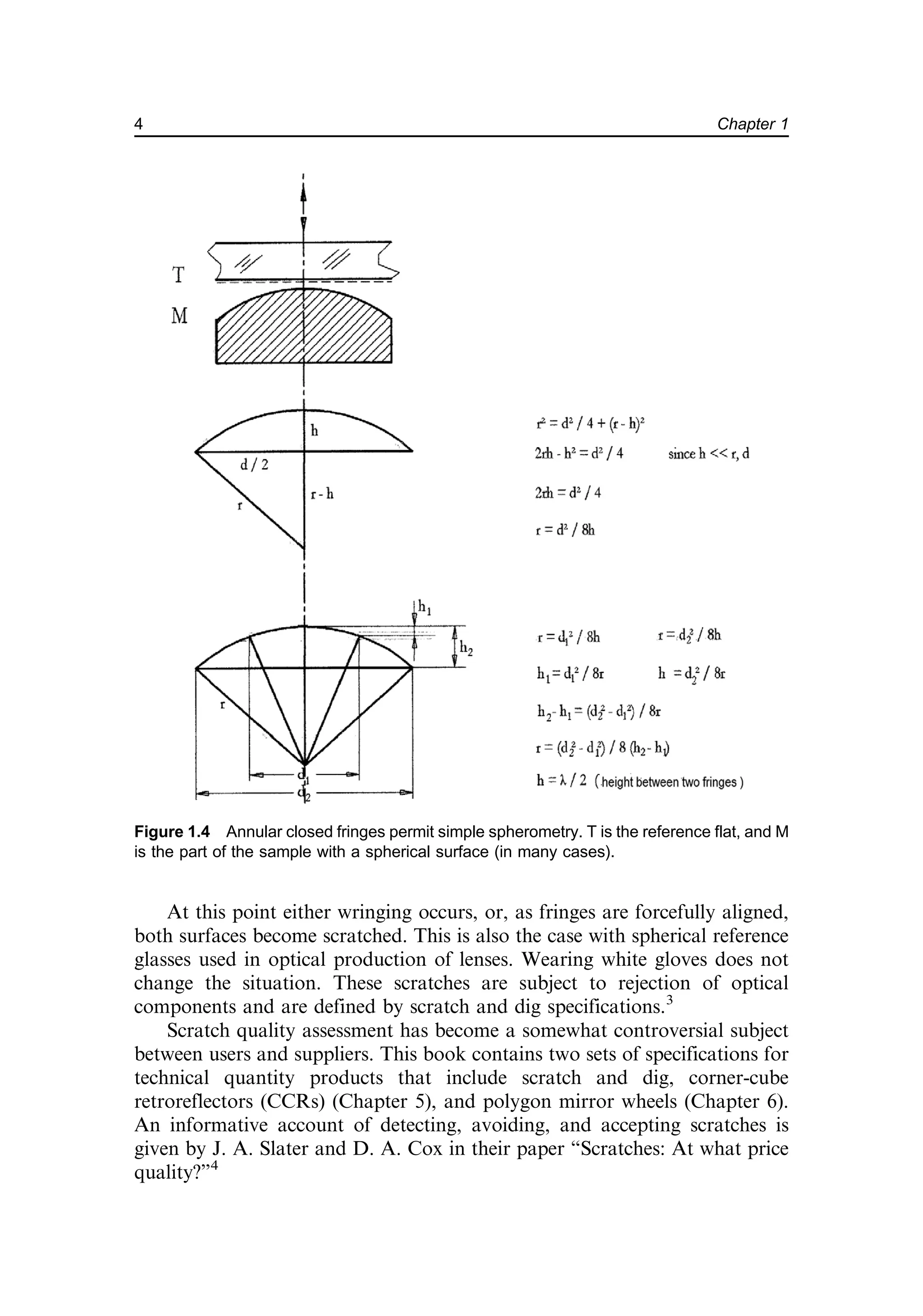
![Measurement of fringe spacing P1 (on an object-to-image scale of 1:1 and
in the same dimension as l) provides the included angle a1 ¼ (l/2)/P1, with
l ¼ the wavelength of light used. Above the minute wedge Da on the
workpiece, one sees fringes of a different spacing P2 [as shown in Fig. 1.5(a)]:
(a þ Da) ¼ (l/2)/P2. The wedge angle g on the surface is
g ¼
l
2
1
P1
1
P2
¼ a1
DP
P2
: ð1:1Þ
Narrowing the distance between the reference and the workpiece [Fig. 1.5(a)]
by some load without changing a causes the fringes to “walk” parallel to
themselves until the two surfaces come into contact, usually at the periphery.
The contact zone is characterized by complete darkness and is the hinge or
Figure 1.5(a) l/2 interference fringes in yellow sodium light between two bare glass plate
surfaces separated by omnipresent dust. The areas of almost complete surface contact
appear darker and less dark with increasing gap t.
5
Known Methods: An Assessment of the State of the Art—Newton and Fizeau](https://image.slidesharecdn.com/2482702-250622075739-62e343b5/75/Interferometry-For-Precision-Measurement-Peter-Langenbeck-24-2048.jpg)

![fringes shown inFig. 1.5(a), but multicolored, as showninFigs.1.5(b) and 1.7(a).
Note that these are natural colors and not artificial coding colors. The darkest
fringe appearing in the middle of the sample in Fig. 1.7(a) automatically
calibrates the distance variation between the entire sample surface and the
reference, both being monotonic. In terms of any optical wavelength, this
calibration, which is chosen from spectral lamps, is called absolute because the
wavelengths of these spectral lines are among the most accurate (and low-
cost!) length standards in physics.
One tacitly assumes no departures from flatness on the reference. An
often-overlooked fact is that the calibration applies to the total of the distance
changes between the two surfaces, not of only one surface. In order to prove
flatness beyond the commercially available quality of “flats,” considerable
effort was undertaken to verify flatness absolutely by successively comparing
two or three flats. The interested reader will find a method developed by
R. Schulz7
and B. S. Fritz.8
Note that taking a computer recording of an
interferogram from a reference known to be “perfect” and subtracting the
same from a sample interferogram is a step in the right direction but does not
replace absolute measurement.
Figure 1.6 illustrates a quantitative interpretation of fringes seen between
a flat reference glass and a flat sample with a rectangular relief profile (with a
groove of depth Dt). The bottom of the groove is parallel to the ground, and
distance t is unknown. In Fig. 1.6(b), the fringes are made to extend parallel to
the groove and have the same spacing and direction above the sample surface
and above the base of the groove, both partial surfaces being parallel. All that
one can derive from such stationary fringe patterns is the angle between the
plates, the flatness of the ground and groove, and the parallelism between the
ground and groove. With the order-of-interference number on the ground
before the groove unknown [tground ¼ n1 (l/2)], and for the first fringe in the
groove [tgroove ¼ n2 (l/2)], which is likewise unknown, the difference (n2 – n1) ¼
Dn also remains unknown.
Changing the plates’ wedge orientation from that shown in Fig. 1.6(a) to
that shown in Fig. 1.6(b) causes the fringes to extend orthogonally to the
groove, allowing them to be tracked; within one order, it becomes possible to
determine Dt ¼ (l/2) (DP/P); at greater values of n,
Dt ¼
l
2
n þ
DP
P
: ð1:3Þ
Experimental use of the groove test for defining the direction of the
zeroth-order location is illustrated in Fig. 3.4(c). The groove test using
Eq. (1.3) in the schematic shown in Fig. 1.6 is useful for determining the
thickness of thin vacuum-deposited layers. Detection of the uniformity of
coating thickness within a few nanometers is an important application of
interferometry.
7
Known Methods: An Assessment of the State of the Art—Newton and Fizeau](https://image.slidesharecdn.com/2482702-250622075739-62e343b5/75/Interferometry-For-Precision-Measurement-Peter-Langenbeck-26-2048.jpg)
![A note for the practitioner
The groove edge test, as shown in Fig. 1.6(b), is an indispensable tool in thin-layer
technology (vacuum coatings) and lends itself to multipass interferometry. The
direction of walkoff being parallel to the groove (see Chapter 10) results in
approximately five times enhanced sensitivity (l/10 fringes). Calibration masters
are produced by diamond machining of a flat with a defined groove depth (see
Section 1.6.2).
1.2 Limited Use of Newton’s Method
At this point we can recognize the limitations of simple testplating, or
Newton’s method. Some of these limitations are listed here:
• It is a method, not an instrument.
• The distance between the sample and the reference is so small that
alignment of fringes in any direction to suit evaluation is almost
impossible [changing alignment between cases (a) and (b) in Fig. 1.6
might not be possible without undue force].
• Rapid sequential testing is not possible.
Figure 1.6 Fringe alignment of spacing and orientation to suit evaluation: (a) The apex of
the wedge is parallel to the groove, with regular spacing P. At the entry and exit to the
groove, P1 changes to P2 [Dt ¼ (l/2)(n (DP/P)], with factor n remaining unknown.
(b) The apex of the wedge crossing the groove. The order-of-interference number n now
becomes measurable [see Fig. 1.8(a)]. Identical reflectivity of groove bottoms and of the
flat is assumed.
8 Chapter 1](https://image.slidesharecdn.com/2482702-250622075739-62e343b5/75/Interferometry-For-Precision-Measurement-Peter-Langenbeck-27-2048.jpg)
![• As shims are inserted, interference patterns are lost; fringes are retained
only when the shims are very thin, as in. e.g., cigarette paper or three
thin spots of diluted Zapon lacquer.
• A wide variety of samples are either too large for the reference or too
small for visual assessment; or they have “optical” surfaces on complex
mechanical parts, or are too deformable (as are wafers). These samples
need external auxiliary alignment.
• The advantageous feature of identifiable white-light interference allows
one to follow a sample’s topography, even if the surface is interrupted
by long, empty intervals. However, white-light interferometry only
works with narrow gaps; it eliminates the option of simple testplating
and requires special instrumentation.
1.3 Other Methods of Interferometry
Classical interferometers provide solutions to dividing one (usually colli-
mated) light bundle into two bundles of equal diameter, each having, for
instance, 45% of the original luminance. The bundle that is returned unaltered
into the instrument serves as the reference to the other bundle, which is
returned in the same fashion after reflection at the sample. Recombination of
the two bundles generates the interferogram, which is recorded on film or
electronic camera at the location of the sample’s image. The reader can find
ample literature on interferometers in Ref. 7. For ordinary flat work, the
interferometer results are equivalent to the testplated interferogram. However,
instrumental solutions are much more costly than simple testplates, which
might be selected cuts from low-cost float glass.5
Most interferometers are named after their inventors, well-known
physicists such as Michelson or Fizeau. An experimental combination of a
Fizeau (multiple-beam) and a Michelson (two-beam) interferometer was
assembled in order to accompany the graphical vector display of interference,
contrast, finesse, and contrast reversal, as shown in Fig. 3.24(a), with Fig. 3.24(b)
being the corresponding representative interferogram.
A classic “old timer” of precision engineering and metrology interferom-
eters is the Köster interferometer, whose basic configuration is based on the
beam-dividing Köster prism, shown in Fig. 10.4(a). The classic application is
in length metrology, which requires equalization of the length of the two
bundles reflected at a sample and at a movable reference mirror. White-light
interference with its dark center is observed [see Fig. 1.7(a)], indicating
coplanarity between the longitudinally mobile reference and the top surface of
the sample, for instance, a slip gauge resting on a slightly wider auxiliary
mirror. That auxiliary mirror’s coplanarity with the moveable reference
mirror indicates the end of travel and represents the thickness of the slip
gauge. Surface errors such as turned-down edges and wedge angles are seen in
9
Known Methods: An Assessment of the State of the Art—Newton and Fizeau](https://image.slidesharecdn.com/2482702-250622075739-62e343b5/75/Interferometry-For-Precision-Measurement-Peter-Langenbeck-28-2048.jpg)
![the same interferogram as well. The length of travel between the two
coplanarity positions is measured by counting the fringes obtained when using
a long-coherence-length laser as a light source in addition to white light
(compare with Fig. 1.17).
Another feature of the Köster prism is its angular null sensing around an
axis parallel to the apex of the Köster prism (meaning no pyramidal error).
For this to occur, only one mirror simultaneously returns both interferometer
bundles; its nutation provides an opportunity to align the interferogram in
Fig. 1.7(a) to show the dark white-light interference in the complete (50-mm
diameter) field of view (FOV). This type of interference autocollimation
defines an angular null to about 0.02 arcsec, a feature that will be discussed
further in Chapter 3 [Fig. 3.7(d)] and Section 5.2.
Any instrumental interferometer allows for axial displacement of either
the sample or the reference mirror in order to obtain the desired fringe
alignment; this allowance is not offered by testplating. In Section 1.6.2 we
look at different light sources that allow the resolution to be pushed to a range
of 0.001 mm (white light) to 10,000 mm (laser) before losing interference
contrast. In addition, the reference path can be conveniently inclined much
farther than in testplating to align fringes to suit their interpretation.
Coincidence of two slightly tilted coherent white-light flat wavefronts is
shown in Fig. 1.7(a). The apex with respect to the zeroth-order axis leads
through the center of the image and can be turned around at will by alignment
of either the reference or the sample mirror.
Note that in the classical Newton contact testplate setup, one of the two
reflected wavefronts can be inclined as well, but only around an apex that is on the
sample edge or is far outside the edge, and at the expense of inopportune squeezing.
Some technical workpieces have more than three, neither adjacent nor
cohesive, partial surfaces that are specified to be coplanar. The interferometer’s
reference marks indicate the zones that are closest to the specified coplanarity.
Figure 1.7(a) Interferogram from a dual-beam (Michelson) interferometer with white-light
interference between two flat wavefronts that are slightly inclined toward each other. The
apex is now in the center of the FOV and identified by a dark fringe (the zeroth-order
interference). Such an interferogram can be recorded with an instrument similar to the one
shown in the schematic in Fig. 1.9 or with equivalent optical hardware imbedded into a
granite block (see Fig. 1.8).
10 Chapter 1](https://image.slidesharecdn.com/2482702-250622075739-62e343b5/75/Interferometry-For-Precision-Measurement-Peter-Langenbeck-29-2048.jpg)
![A typical example is shown in Fig. 1.7(b). Coplanarity and departures thereof
can be determined interferometrically but only with an ear-marked short-
coherence-length light source (Section 1.3). It is not possible to follow the order
number of interference with laser illumination [Fig. 1.7(c)]; however, white-light
interference permits one to follow the ear-marked fringes (observing continuity
of colored and zeroth-order fringes), ascertaining at least some coplanarity. The
word some refers to another surprise: a minute axial displacement of the
reference mirror makes the fringes walk. The walk in this example is away from
the corner or from an edge that is tangent to the momentary best-fit spots.
Figure 1.7(c) A typical white-light application: an interferometric test stand for slip gauge
comparison. After charging the samples (by wringing) onto the air-bearing-supported
reference base and after temperature balancing, all slip gauges should present the zeroth-
order straight fringe interferogram [Fig. 1.7(a)]. Note the air-bearing table for positioning the
multiple samples under the interferometer without need for realignment.
Figure 1.7(b) A 15-mm-long sample (part of the electrical relay) with four feet that have been
precision lapped to be coplanar within 0.1 mm. It is not possible to measure height differences
on this sample with laser illumination; only out-of-parallel samples can be measured.
11
Known Methods: An Assessment of the State of the Art—Newton and Fizeau](https://image.slidesharecdn.com/2482702-250622075739-62e343b5/75/Interferometry-For-Precision-Measurement-Peter-Langenbeck-30-2048.jpg)

![(2) generating lateral and/or rotary motion of a variety of air-bearing
components, whose longitudinal error motion (orthogonal to the granite base)
would be less than detectable by the interferometer integrated onto the
granite. Lateral scanning of samples wider than the FOV of the micro-optics
thus becomes possible. A channel underneath the air-bearing-quality flat
stone contains a small reference flat [labelled L in Fig. 1.9(a)]. The same
channel on the opposing end contains the small collimator.
The granite top surface serves as a base for simple X–Y sliding of a
sample or, for an air-bearing slide of the type shown in Fig. 1.11(a), carrying
samples facing downward and, thus, being moved strictly in a direction
orthogonal to the optical axis. This alignment serves to guide the installation
direction of the microscope’s optical axis to be orthogonal to the
instrument’s axis; fringes of the air-bearing base show no lateral motion
once orthogonality is found and fixed.
Centration measurement has become an important application of this
micro-interferometer: the flat top of the granite block serves as a reference base
for cylindrical disks rotating on a 2- to 3-mm air film. The cylindrical disk,
airborne both on its axial surface facing the granite and at its periphery, can be
centered to coincide with the optical axis by an iterative process of shifting both
the removable sample holder on the spindle and the spindle itself. The latter is
clamped in position by axial preload. Centration is indicated by an artifact, like
the hole for the fiber in a ceramic pin. The hole’s central position within the
connector needs to be certified. The axis of rotation, being parallel to the optical
axis, can be shifted to see the connector’s periphery rotating through the image,
thus enabling a measurement of mechanical centricity and determining
the eccentricity of the fiber. Simultaneously, the micro-interferogram of the
Figure 1.9(a) Design of a Michelson two-beam interferometer with a microscope
attachment (adapted from Ref. 7).
13
Known Methods: An Assessment of the State of the Art—Newton and Fizeau](https://image.slidesharecdn.com/2482702-250622075739-62e343b5/75/Interferometry-For-Precision-Measurement-Peter-Langenbeck-32-2048.jpg)
![well-polished cap of the ceramic pin must confirm the surface form, which is
specified as two symmetric, convex fringes.
Optical components integrated into the rugged granite block use the same
design as the very practical Watson two-beam Michelson interferometer
serving as a microscope attachment [Fig. 1.9(a)].
A note for the practitioner
The task of interferometrically centering a small optical workpiece on an air-
bearing spindle and fixing the same for subsequent center grinding of its
periphery without changing the chuck/holder is made convenient using the
rugged micro-interferometer shown in Fig. 1.9(a). This compact unit can be
repeatedly removed and mounted to the air-bearing stator.
In Fig. 1.9(a), B is the RMS (Royal Microscopical Society) thread
that connects the unit to a microscope with the knurled securing ring.
A monochromatic light source (sodium or mercury lamp) is placed as close as
is convenient to the illumination entry (D), which is a removable filter. E is the
collimation system, which is a beamsplitter cube; F is a removable shutter;
L is the reference mirror; K is the longitudinal alignment adjuster for the
reference mirror; and G and H are the two adjusters for angular alignment of
the reference mirror. The knurled ring (A) fixes the thread (B) to the
microscope. C is the collimating optic, and F is the location for the filter.
Both the Watson dual-beam interferometer and the Integrated Topside
(Intop, from the author’s lab) monoblock micro-interferometer use collimated
light reflected by a sample to measure the sample roughness profile. The
vertical range of these two devices is limited to about 20 mm within the FOV.
Flanks with a pitch equal to the axial wavefront departure from flatness in
relation to lateral distance change can be measured with 0.015 mm/mm with
4 for the monoblock, and 0.04 mm/mm with 10 for the Watson, where the
units mm/mm indicate the steepness of the flank of a deep groove divided by
the width of the same. A thorough analysis of beam walkoff on steep flanks
inspected by micro-interferometers is provided by H. Mykura.9
In order to make this measurement with white light, one must mechanically
equalize the optical path lengths from the beamsplitter to the reference and,
likewise, to the sample within one representative wavelength (e.g., green). The
criterion for this balance is the dark zeroth-order interference fringe that passes
extremely fast through the FOV upon alignment.
This and other microscopes (such as various Linnik microscopes) are
typical. Figure E7 in Ref. 10 shows the use of fine threads for the control of
mirror movement. (Note that the nanoscrew (Ref. 10, Fig. 1.9) is a useful
device for such supersensitive alignment.)
A forewarning of the fast-approaching dark fringe is obtained by mixing
white light with long-coherence-length light of an additional light source (laser).
A description of this light mixing is found in Figs. 10.1(a) and (b). The process of
aligning the length of an interferometer arm is made convenient when observing
14 Chapter 1](https://image.slidesharecdn.com/2482702-250622075739-62e343b5/75/Interferometry-For-Precision-Measurement-Peter-Langenbeck-33-2048.jpg)

![1.4 Desirable Features for Safe, Applicable, and Economic
Interferometry
1.4.1 Commercial coherent white light
From almost any thermal white-light source (e.g., a tungsten lamp), some small
part of the emitted light can be made to behave coherently. To show this,
Verdet set up the experimental parameters shown in Fig. 1.10(a), which
demonstrates his coherence condition. With the notations in this figure, a lateral
size a of a primary or secondary light source is required; a depends on F being
the focal length of the collimating objective with its clear diameter d, and on x
being the lateral distance within which coherence is desired (usually d/2).14
Verdet’s criterion for coherence,
x
a
F
l
4
, ð1:4Þ
allows one to estimate the useful dimension of a. If a represents the width of a
fine controllable slit (a common element of instrumentation in an optical
laboratory), then a 2- to 5-mm slit width or pinhole size suffices to produce
quasi-coherent light from thermal white light focused on the back of the slit or
pinhole. High-pressure spectral point discharge lamps (mercury) provide
enough brilliance to allow a to be sufficiently small to satisfy the Verdet
condition and transmit enough light for practical use.
With l approximated as 6 10–4
mm and b ¼ 1000 mm, we can apply a
secondary light source of approximately 0.01 mm in diameter in order to
obtain white-light interference across a beam, reflected by the two surfaces of
an uncoated 0.5-mm-thick glass plate with no spectral filter applied. (Recall
Figure 1.10(a) Diagram illustrating a collimated beam of coherent light that satisfies
Verdet’s criterion for coherence. Light from an extended light source—thermal white or
monochromatic—is focused onto the back of an opaque stop, carrying a pinhole of diameter
a [see Fig. 1.10(b)]. The fine control of focal distance (F, in this schematic figure) will be
discussed in Sections 3.8 and 5.2.3.
16 Chapter 1](https://image.slidesharecdn.com/2482702-250622075739-62e343b5/75/Interferometry-For-Precision-Measurement-Peter-Langenbeck-35-2048.jpg)
![the beautiful colors in an oil film on the surface of a water puddle on a city
street.) This secondary light source might be the end of a thin fiber optic cable,
or a commercial pinhole illuminated from behind by an extended light source,
as otherwise used for testplating. Figure 1.10(b) illustrates a common
arrangement for focusing the light source onto the pinhole stop (secondary
light source).
The following is a brief excursion for the experimenter: The transition
from incoherent to coherent (or interference-qualified) thermal light source
illumination will be illustrated in Section 8.1.3 and in the strioscopy setup
shown in Fig. 8.4(b). The narrowing of the illumination slit allows
interference to appear within in a so-called shadow image of a phase object
[for instance, a flame, as in Fig. 8.4(b)]. Figure 1.10(c) illustrates the coherence
behavior of this white-light illumination in relation to other types of
illumination used for interferometry. Today’s laser diodes can be electroni-
cally controlled between white-light short coherence length and gas-laser-like
long coherence length. Long before lasers became available, this type of
illumination was used in all interferometer configurations, some of which are
still in use today.
1.4.2 Light sources for increased distance from reference to sample
White light does not produce interference with gaps dx between mirrors any
larger than 0.002 mm. Simple experimentation allows one to find spectral-
light lamps with well-established coherence lengths by inserting three small,
equally sized bits of thin shim between the sample and the reference plate with
successively increasing thicknesses. The yellow fringes of the sodium vapor
lamp might still be visible; however, they have less contrast than those
obtained with (shimless) direct contact. The green-mercury-lamp fringes
tolerate thicker shims until the contrast disappears. Well-established coher-
ence lengths are listed in Table 1.1.15
A very thin material/film that can be used as shims is Mylar®
foils of 2-, 4-,
6-, 8-, 14-, and 18-mm thickness.16
One problem encountered with shims is
Figure 1.10(b) Transforming an extended light source into a 1D uniaxial collimated beam
of interference-qualified light, or “more light through a smaller hole.” The spectral lamp can
be replaced by an LED device.
17
Known Methods: An Assessment of the State of the Art—Newton and Fizeau](https://image.slidesharecdn.com/2482702-250622075739-62e343b5/75/Interferometry-For-Precision-Measurement-Peter-Langenbeck-36-2048.jpg)


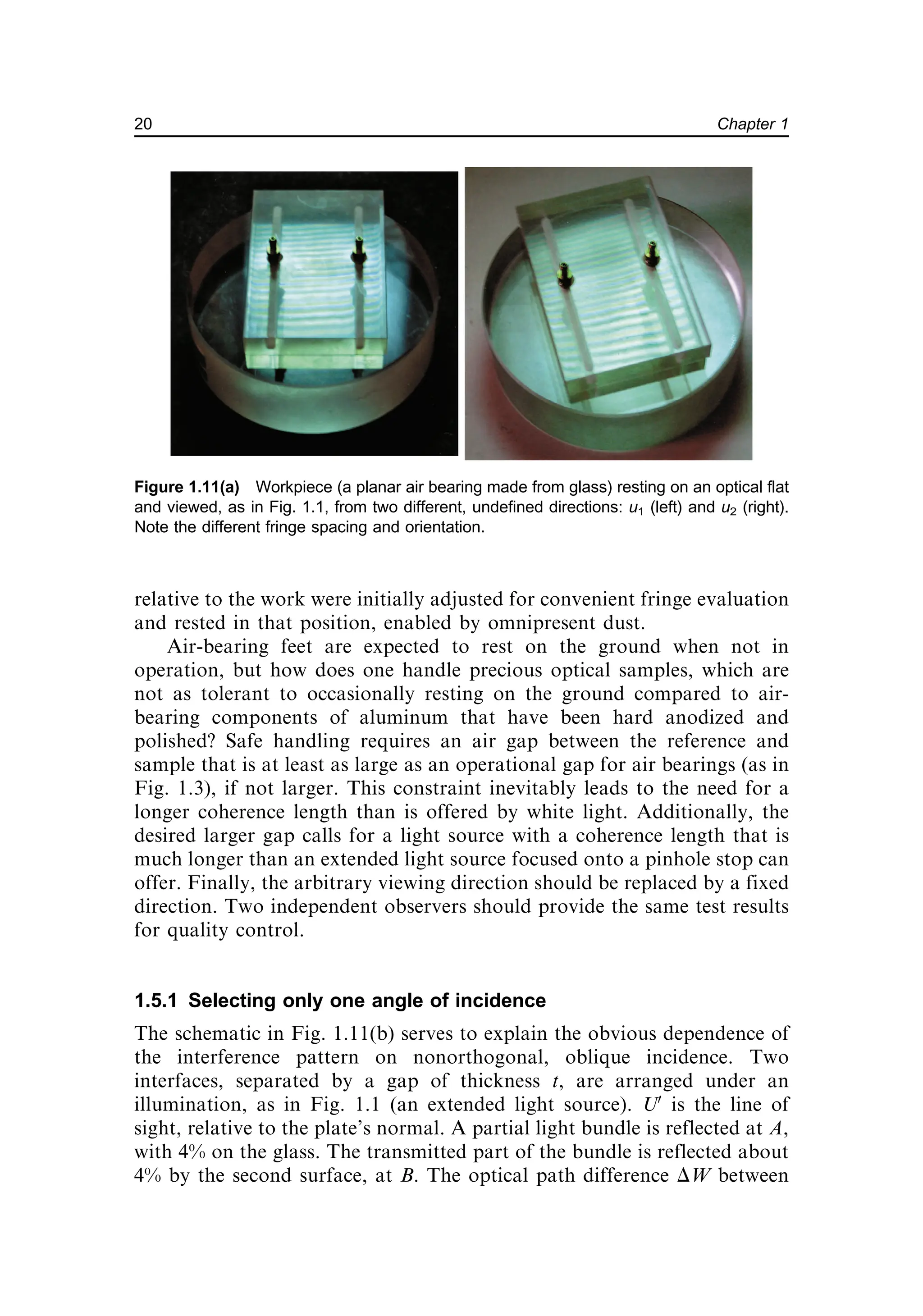

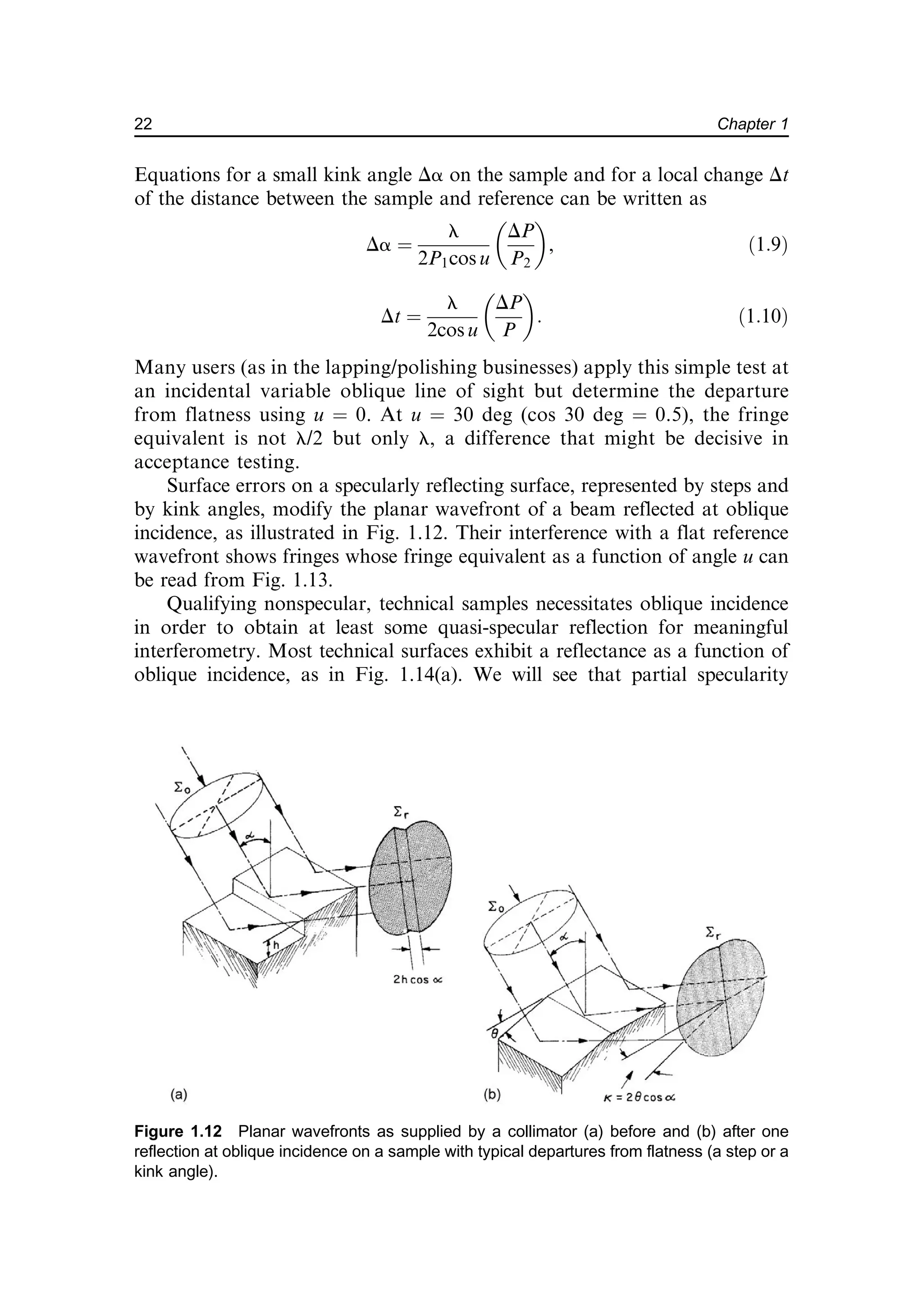


![as suggested in Fig. 1.14(c). A granite reference plate can serve as angular
zero for the installation of the collimator. Simple, low-cost, home-made
equipment as shown in Fig. 1.14(c) suffices. Hidden in the green box is the
Z-folded version of a collimating optic.
Larger angles of incidence on non–fully specular surfaces, for
instance, from 75 to 89 deg, are obtained by shining the collimated light
through the cathede, one of the two identical short flanks of the right-
angled prism, as shown in Fig. 1.14(b). A simple method allows one to
incline the laboratory “do it yourself” collimator for use at zero, at
oblique, and in combination with said 90-deg or Dove prism, at grazing
incidence of the collimated light on the sample. Figure 1.14(d) shows the
simple implementation and use of a 90-deg prism with its hypotenuse
serving as a flatness reference. The flatness prism exhibits interference
with a 1-mm fringe equivalent. Figure 2.1(d) illustrates the most primitive
way of testing flatness, in violation of the noncontact measurement rule.
In Section 9.1 we will see granite beds being tested for flatness with the
grazing collimation direction set at approximately an 87-deg angle of
incidence, which corresponds to a 6-mm fringe equivalent.
Figure 1.14(c) Collimator with Z-folded beam inclined to suit. The image is seen on a
transparent paper or on ground glass [Fig. 1.14(d)]. Note that one surface, the prism’s
hypotenuse, serves as both the beamsplitter and the reference.
25
Known Methods: An Assessment of the State of the Art—Newton and Fizeau](https://image.slidesharecdn.com/2482702-250622075739-62e343b5/75/Interferometry-For-Precision-Measurement-Peter-Langenbeck-44-2048.jpg)

![equivalent, and vice versa. Quantitatively, these error contributions
remain rather negligible in the 1- to 3-mm range of fringe equivalents
but increase rapidly as the angle of incidence is preset to obtain a larger
grazing incidence relative to the substrate, producing fringes desired to
have about 3.5- to 8-mm fringe equivalent. In this range of very oblique
(grazing) incidence, both the sample alignment and the sample departures
from flatness entrain a built-in uncertainty in the amount and location of
error. The distance between the sample and the reference will have a
severe impact on the interferogram. In addition to pre-aligning the angle
of incidence to the prism’s cathede (starting where zero is the angle at
which total internal reflection occurs), it has become common practice to
employ calibration masters.
1.6.2 Calibration masters
Flatness calibration masters, which are precision-polished glass disks or
testplates, are offered by different companies, quoting best usual flatness in
the specification category of l/20 and diameter to suit the application and
the budget. Less costly are circular cuts (water jet) from selected float
glass.18
Process steps in the generation of a calibration master are shown in
Fig. 1.15. In the center of the flat substrate, one polishes an artificial error in
the form of a shallow spherical dish having a depth of, for instance, 3 mm
and a diameter of ~10 mm.
The calibration master is made to have a peripheral zone(s) that
represents the “flat” condition. For the prism, this means soft contact to the
hypotenuse (the master and reference are parallel). Figure 1.16 shows a flat
master with an artifact polished into the surface. The calibration follows the
procedure shown in Fig. 1.15. The master is placed under a flatness prism
interferometer [as in Fig. 1.14(b)].
Diamond micromachining of aluminum or brass makes possible the
fabrication of a wedge with a mirror-like surface extending between two
coplanar flanks (a wedge machined into a flat surface). Figure 1.17(a)
shows an example of a linear wedge with 8.97-mm depth between the
flat zones, recorded in a Michelson interferometer. The wedge presents
28 l l/2 fringes. In order to calibrate a flatness prism to present 3-mm
fringes, one would need to align the incident angle such that one obtains
8.97/3 fringes across the wedge. The dimension on the long side would be
70 mm.
In calibrating a prism interferometer to present 1-mm fringes, one would
trim the angle of incidence to the prism’s cathede to obtain 8.5 fringes across
the wedge. The calibration master in Fig. 1.17(a) can be used in any
interferometer operating with normal incidence due to the coplanar flat
zones flanking the wedge.
27
Known Methods: An Assessment of the State of the Art—Newton and Fizeau](https://image.slidesharecdn.com/2482702-250622075739-62e343b5/75/Interferometry-For-Precision-Measurement-Peter-Langenbeck-46-2048.jpg)


![diamond-sawed substrates [examples in Figs. 8.2(a) and (b)] in the early
production phases prompted the desire to have contactless, 5-mm fringe-
equivalent instruments with 125-mm diameter and l/20 accuracy. Inconsis-
tent results and differences between instruments from the same and from
different suppliers were related to poor reference surface, collimation errors,
and the distance between the sample and the prism’s hypotenuse. Scrutiny
was also focused on the calibration of the fringe equivalent ascribed to an
instrument.
The wedge calibrating master has an inherent problem: The light leaving
the prism in grazing excidence strikes the sample’s surface under a different
angle, depending on the wedge’s direction relative to the direction of view.
Figures 1.17(f) and (g) represent the same calibration master seen from
opposite directions.
Figure 1.17(e) Calibration master turned 45 deg. Fringe equivalent set for 2-mm fringes,
recognized by 8.5 fringes on the flat zone. This case corresponds to the case shown in
Fig. 1.12(b).
Figure 1.17(f) 1-mm fringes with beam walkoff into the open wedge (8 fringes).
31
Known Methods: An Assessment of the State of the Art—Newton and Fizeau](https://image.slidesharecdn.com/2482702-250622075739-62e343b5/75/Interferometry-For-Precision-Measurement-Peter-Langenbeck-50-2048.jpg)
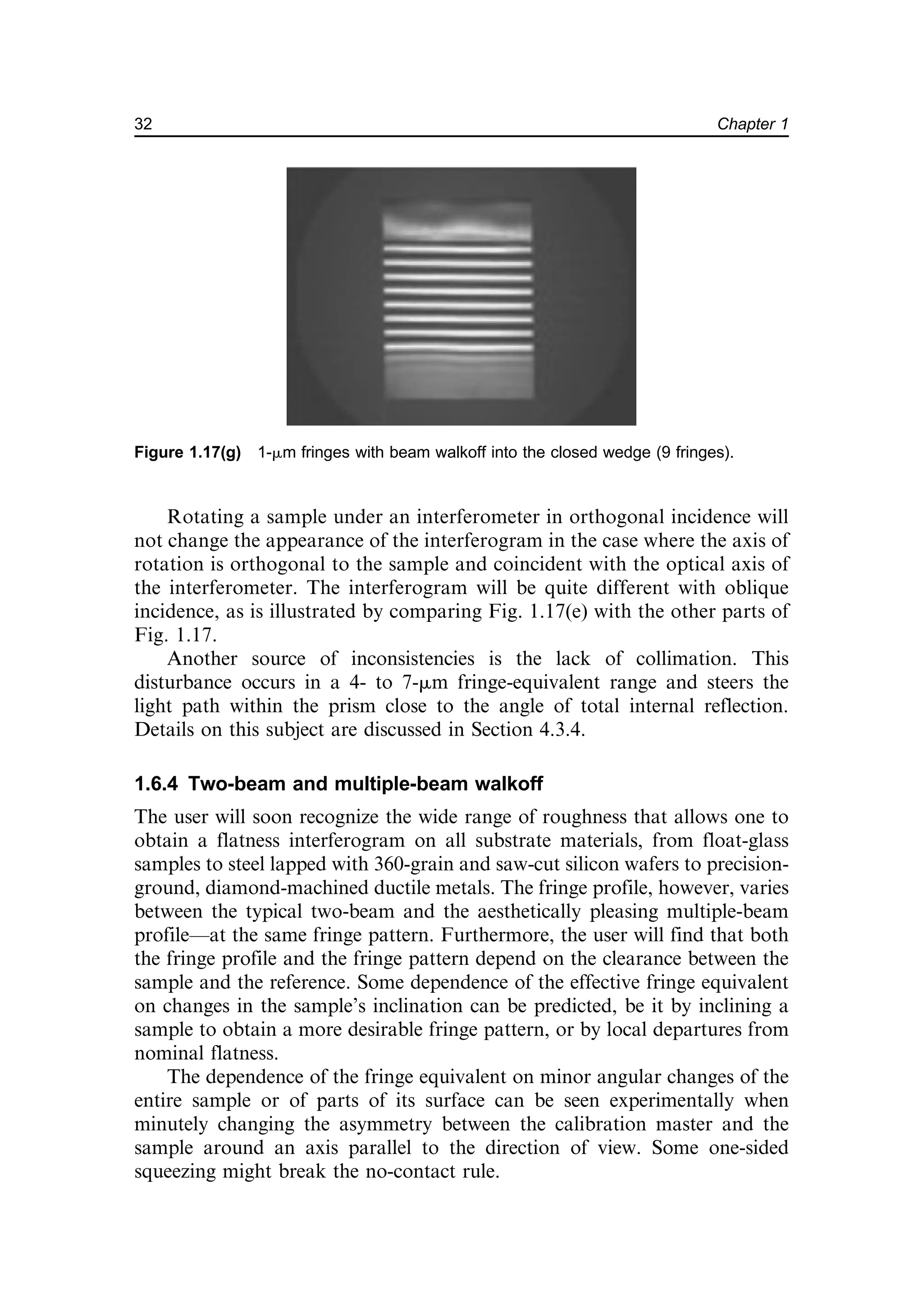

![When adjusting the angle of incidence to the prism, the practitioner will
instantly recognize the light scattered off of constructive multiple-
reflection interference paths, striking the sample within the narrow cavity.
The bright zones can be observed at any angle through either of the two
cathedes of the prism. The 90-deg prism can be truncated to become a Dove
prism [Fig. 1.18(a)], allowing convenient, instant orthogonal observation of the
surface under the hypotenuse, without the impractical, perspective, uniaxial
compression in the exiting beam. Figure 1.18(b) is an example of these scattered-
light fringes.
While discussing the occasional good use of stray light, let us mention a
side effect from Chapter 9. Refer to Fig. 9.6(a), which shows a large sample
to be inspected by a grazing-incidence Fizeau interferometer. Two mirrors,
T (the semitransparent Fizeau reference) and M (the flat reference), are
located with symmetric angles relative to the large semifinished flat sample,
in order to obtain a long-path grazing-incidence Fizeau configuration. Let
us select an angle of incidence to the sample from Fig. 1.12 that is 80 deg
(approximately a 2-mm fringe equivalent). In this Fizeau configuration, the
beam passes the sample twice (back and forth), resulting in an effective
fringe equivalent of 1 mm.
Figure 1.18(c) shows scattered-light fringes on the nearly finished 400-mm
[outside diameter (OD)] flat mirror. The sample was spray coated with
silver.20
The thickness variation of this spray silver coating was measured to
Figure 1.18(b) Collimated green laser light shone through the 90-deg prism, as in
Fig. 1.14(c), producing 2-mm fringes of a flat lapped ceramic sample (left). The dark flatness
fringes are seen on a transparent drafting paper screen (right). At least two consecutive,
quasi-specular reflections on the sample are required in order to produce the bright
interference bands that generate the scattered light. The sample is a mass-produced
ceramic seal of standard water faucets; less than 2¢ per piece is allowed for continuous
process quality control.
34 Chapter 1](https://image.slidesharecdn.com/2482702-250622075739-62e343b5/75/Interferometry-For-Precision-Measurement-Peter-Langenbeck-53-2048.jpg)
![be less than 30 nm. The record was taken in dim ambient light. The expenses
for the low-cost laboratory components are substantially less than for a full-
sized interferometer; needless to emphasize is the profitable use of an air-
bearing slide or of a rotary table for complete lateral scanning [Fig. 9.3(b)].
1.6.6 The scatter flat test
Global reflectance, characteristic of a technical surface such as the finest
lapped ceramic wafer carrier or a glass mirror shortly before being a 100%
mirror, offers intriguing opportunities for metrology. An expanded
collimated laser beam, directed obliquely onto the cleaned surface, produces
scattered light that can be observed on the surface as a zone of some
brightness from nearly any direction. In addition, the reflection characteris-
tically shows a lobe of quasi-specular reflection, much like in Fig. 1.14(a).
The specular component might even be strong enough to allow at least one
back and forth reflection, thus establishing a long-path Fizeau interferome-
ter. On a sample (being much larger in diameter than the available
collimated beam), one can recognize the light path on the dull surface
orthogonal to the scattering mirror surface. The experimental setup is
reproduced in Fig. 1.18(c), showing a 400-mm OD sample mirror, the front
Fizeau mirror T, and part of the rear mirror M. In the defocusing plane one
can see the bright focal image produced by T and, depending on the grazing
angle chosen, at least one or even more foci. The next focal image represents
two passages of the beam over the sample (back and forth); the first two foci
Figure 1.18(c) Due to the double reflection at the mirror and the preset 80 deg of incidence,
the Fizeau scatter interference levels represent a mutual distance, as viewed orthogonally on
the mirror, with 1 fringe equivalent ¼ 0.913 mm at the HeNe laser wavelength.
35
Known Methods: An Assessment of the State of the Art—Newton and Fizeau](https://image.slidesharecdn.com/2482702-250622075739-62e343b5/75/Interferometry-For-Precision-Measurement-Peter-Langenbeck-54-2048.jpg)


![June 20.
June 21.
June 22.
June 23.
June 25.
June 26.
prepare report the Constitution. The whole proceedings as
referred are as follow [14]:
[14] Madison's note says: here copy them from the Journal p.
207. In the Journal they are given as having been collected
from the proceedings of the convention, as they are spread over
the journal from June 19th to July 26th.—Journal of Federal
Convention, 207. The dates show when the resolutions were
agreed to, and are correct.
I. Resolved, That the Government of the
United States ought to consist of a supreme
legislative, judiciary, and executive.
II. Resolved, That the legislature consist of
two branches.
III. Resolved, That the members of the first
branch of the legislature ought to be elected
by the people of the several states, for the
term of two years; to be paid out of the publick treasury; to
receive an adequate compensation for their
services; to be of the age of twenty-five years
at least; to be ineligible and incapable of
holding any office under the authority of the United States
(except those peculiarly belonging to the functions of the first
branch) during the term of service of the first branch.
IV. Resolved, That the members of the
second branch of the legislature of the United
States ought to be chosen by the individual
legislatures; to be of the age of thirty years at
least; to hold their offices for six years, one
third to go out biennally; to receive a
compensation for the devotion of their time to the publick
service; to be ineligible to and incapable of holding any office,](https://image.slidesharecdn.com/2482702-250622075739-62e343b5/75/Interferometry-For-Precision-Measurement-Peter-Langenbeck-58-2048.jpg)


![July 26.
XXIII. Resolved, That it be an instruction to
the committee, to whom were referred the
proceedings of the convention for the
establishment of a national government, to receive a clause or
clauses, requiring certain qualifications of property and
citizenship, in the United States, for the executive, the judiciary,
and the members of both branches of the legislature of the
United States.
With the above resolutions were referred the propositions offered
by Mr
C. Pinckney on the 29th
of May, by Mr
Patterson on the 15th
of June. [15]
[15]Aug 1. 1787 Williamsb.
Dear Col.
We are here I believe every where all Impatience to know
something of your conventional Deliberations. If you cannot tell
us what you are doing, you might at least give us some
Information of what you are not doing. This wd afford food for
political conjecture, and perhaps be sufficient to satisfy present
Impatience. I hope you have already discovered the means of
preserving the American Empire united– that the scheme of a
Disunion has been found pregnant with ye greatest Evils–But we
are not at this distance able to judge with any accuracy upon
subjects so truly important interesting as those wch must
engage you at present–We can only hope, that you will all
resemble Cæsar, at least in one particular: 'nil actum reputans si
quid superesset agendum';– that your Exertions will be
commensurate to ye great Expectations wch have been formed....
J. Madison. [A]
[A] President of William and Mary College, and the
first Bishop of the Episcopal Church in Virginia. He
was a second cousin of James Madison, of Orange.
(Mad. MSS.)](https://image.slidesharecdn.com/2482702-250622075739-62e343b5/75/Interferometry-For-Precision-Measurement-Peter-Langenbeck-63-2048.jpg)


![Monday August 6TH. in Convention
Mr
John Francis Mercer from Maryland took his seat.
Mr
Rutlidge delivered in the Report of the Committee of detail as
follows: a printed copy being at the same time furnished to each
member [16]:
We the people of the States of New Hampshire,
Massachusetts, Rhode-Island and Providence Plantations,
Connecticut, New York, New Jersey, Pennsylvania, Delaware,
Maryland, Virginia, North-Carolina, South-Carolina, and Georgia,
do ordain, declare, and establish the following Constitution for
the Government of Ourselves and our Posterity.
[16] Madison's printed copy is marked: As Reported by Come of
Detail viz of five. Aug. 6. 1787. It is a large folio of seven pages.
In the enumeration of the Articles by a misprint VI. was repeated,
and the alterations in Article VII. and succeeding articles were
made by Madison. In Sect. II of Article VI., as it was printed, it
appeared: The enacting stile of the laws of the United States
shall be. 'Be it enacted and it is hereby enacted by the House of
Representatives, and by the Senate of the United States, in
Congress assembled,' which Madison altered to read: The
enacting stile of the laws of the United States shall be. 'Be it
enacted by the Senate representatives, in Congress
assembled.' The printed copy among the Madison papers is a
duplicate of the copy filed by General Washington with the papers
of the Constitution, and Sec. II is there given as actually printed.
—Journal of the Federal Convention, 219. (Const. MSS.)
Madison accurately transcribed the report for his journal and it
is this copy which is used in the text.](https://image.slidesharecdn.com/2482702-250622075739-62e343b5/75/Interferometry-For-Precision-Measurement-Peter-Langenbeck-66-2048.jpg)