Download as PDF, PPTX
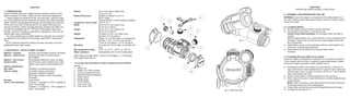

The document is a user manual for Aimpoint's CompM3 and CompML3 reflex sights, detailing their specifications, installation procedures, and maintenance guidelines under various conditions. It emphasizes proper zeroing techniques, lens care, and troubleshooting steps for common issues, such as a non-appearing red dot. The manual also includes adherence to user precautions to ensure optimal performance in extreme climates and operational environments.


