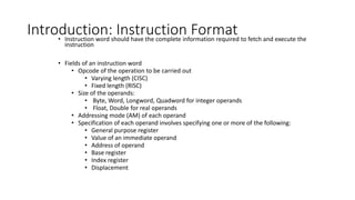
Introduction: Instruction Format
•Instruction word should have the complete information required to fetch and execute the
instruction
• Fields of an instruction word
• Opcode of the operation to be carried out
• Varying length (CISC)
• Fixed length (RISC)
• Size of the operands:
• Byte, Word, Longword, Quadword for integer operands
• Float, Double for real operands
• Addressing mode (AM) of each operand
• Specification of each operand involves specifying one or more of the following:
• General purpose register
• Value of an immediate operand
• Address of operand
• Base register
• Index register
• Displacement
2.
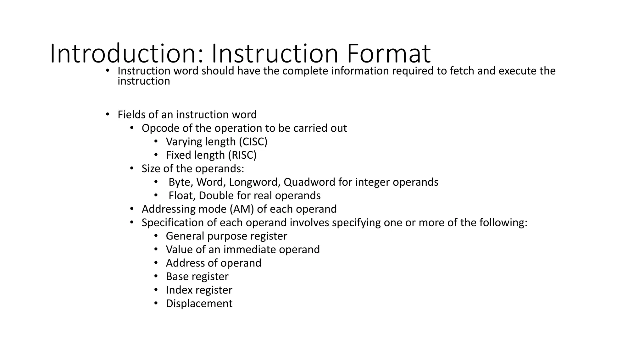
• 3-operand CISCinstruction format:
ADD dst, src1, src2
Instruction Representation
Specification
of src2
Opcode AM of
dst
Specification
of src1
Size of
operands
AM of
src2
AM of
src1
Specification
of dst
Specification
of src2
Specification
of src2
Opcode AM of
dst
Specification
of src1
Size of
operands
AM of
src2
AM of
src1
Specification
of dst
Specification
of src2
Specification
of src2
0011 000 00010
01 110
101
00011 00000
0011
0010
00001
3.
Instruction Representation
• Examplesof RISC instructions:
ADD.w R2, R0, R1
Opcode
Specification
of src
Size of
operands
AM of
src
Specification
of dst
01 101
00010 00000
00001
Opcode
000111
Specification
of src1
Size of
operands
Specification
of dst
Specification
of src2
00001
01 00010 00000
Opcode
000111
LOAD.w R2, [R1][R0]
010011
Opcode
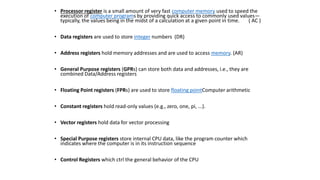
• Processor registeris a small amount of very fast computer memory used to speed the
execution of computer programs by providing quick access to commonly used values—
typically, the values being in the midst of a calculation at a given point in time. ( AC )
• Data registers are used to store integer numbers (DR)
• Address registers hold memory addresses and are used to access memory. (AR)
• General Purpose registers (GPRs) can store both data and addresses, i.e., they are
combined Data/Address registers
• Floating Point registers (FPRs) are used to store floating pointComputer arithmetic
• Constant registers hold read-only values (e.g., zero, one, pi, ...).
• Vector registers hold data for vector processing
• Special Purpose registers store internal CPU data, like the program counter which
indicates where the computer is in its instruction sequence
• Control Registers which ctrl the general behavior of the CPU
6.
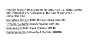
• Program counter:Holds address for instruction (i.e. address of the
next instruction after execution of the current instruction is
completed (PC)
• Instruction Register: holds the instruction code. (IR)
• Temporary register: holds temporary data (TR)
• Input register: holds input character (INPR)
• Output registers: holds output character (OUTR)
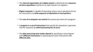
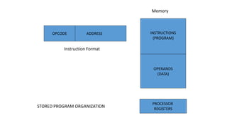
• The internalorganization of a digital system is defined by the sequence
of micro operations it performs on data stored in its registers.
• Digital computer is capable of executing various micro operations & can
be instructed as to what sequence of operations it must perform.
• The user of a computer can control the process by means of a program.
• A program is a set of instructions that specify the operations, operands,
and the sequence by which processing has to occur.
• The data processing task maybe altered by specifying a new program
with different instructions or specifying the same instructions with
different data.
9.
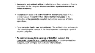
• A computerinstruction is a binary code that specifies a sequence of micro
operations for the computer. Instructions codes together with data are
stored in memory.
• The computer reads each instruction from memory and places it in a
control register. The control then interprets the binary code of the
instruction and proceeds to execute it by issuing a sequence of micro
operations .
• Every computer has its own instruction set. The ability to store and execute
, the stored program concept, is the most important property of a general
purpose computer.
• An instruction code is a group of bits that instruct the
computer to perform a specific operation. It usually divided into
two parts, each having its own particular interpretation.
10.
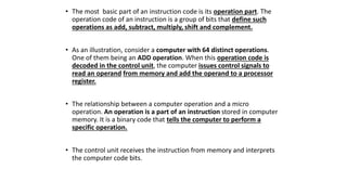
• The mostbasic part of an instruction code is its operation part. The
operation code of an instruction is a group of bits that define such
operations as add, subtract, multiply, shift and complement.
• As an illustration, consider a computer with 64 distinct operations.
One of them being an ADD operation. When this operation code is
decoded in the control unit, the computer issues control signals to
read an operand from memory and add the operand to a processor
register.
• The relationship between a computer operation and a micro
operation. An operation is a part of an instruction stored in computer
memory. It is a binary code that tells the computer to perform a
specific operation.
• The control unit receives the instruction from memory and interprets
the computer code bits.
11.
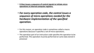
• It thenissues a sequence of control signals to initiate micro
operations in internal computer registers.
• For every operation code, the control issues a
sequence of micro operations needed for the
hardware implementation of the specified
operation.
• For this reason, an operation code is sometimes called a macro
operations because it specifies a set of micro operations.
• The operation part of an instruction code specifies the operation to be
performed. This operation must be performed on some data stored in
processor
12.
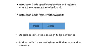
• Instruction Codespecifies operation and registers
where the operands are to be found.
• Instruction Code format with two parts
ADDRESS
OPCODE
• Opcode specifies the operation to be performed
• Address tells the control where to find an operand in
memory.
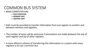
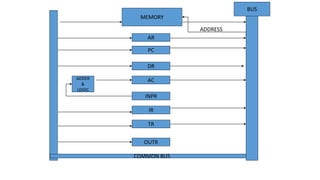
COMMON BUS SYSTEM
•BASIC COMPUTER HAS
EIGHT REGISTERS
MEMORY UNIT
CONTROL UNIT
• Path must be provided to transfer information from one register to another and
between memory and registers.
• The number of wires will be excessive if connections are made between the o/p of
each register and i/p of other registers.
• A more efficient scheme of transferring the information in a system with many
registers is to use a common bus
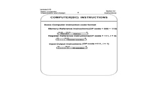
Computer Instructions
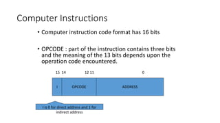
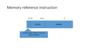
• Computerinstruction code format has 16 bits
• OPCODE : part of the instruction contains three bits
and the meaning of the 13 bits depends upon the
operation code encountered.
I OPCODE
15 14 12 11 0
ADDRESS
I is 0 for direct address and 1 for
indirect address
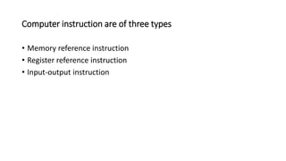
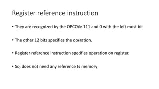
Register reference instruction
•They are recognized by the OPCOde 111 and 0 with the left most bit
• The other 12 bits specifies the operation.
• Register reference instruction specifies operation on register.
• So, does not need any reference to memory
22.
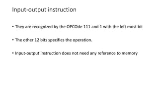
Input-output instruction
• Theyare recognized by the OPCOde 111 and 1 with the left most bit
• The other 12 bits specifies the operation.
• Input-output instruction does not need any reference to memory
![Instruction Representation
• Examples of RISC instructions:
ADD.w R2, R0, R1
Opcode
Specification
of src
Size of
operands
AM of
src
Specification
of dst
01 101
00010 00000
00001
Opcode
000111
Specification
of src1
Size of
operands
Specification
of dst
Specification
of src2
00001
01 00010 00000
Opcode
000111
LOAD.w R2, [R1][R0]
010011
Opcode](https://image.slidesharecdn.com/instructioncodeandformets-251230053918-9c09f169/85/Instruction-code-and-formets-is-a-binary-pattern-3-320.jpg)


![18. Booths Algorithm in computer [Autosaved].pptx](https://cdn.slidesharecdn.com/ss_thumbnails/18-251214092304-35cbd543-thumbnail.jpg?width=640&height=640&fit=bounds)


