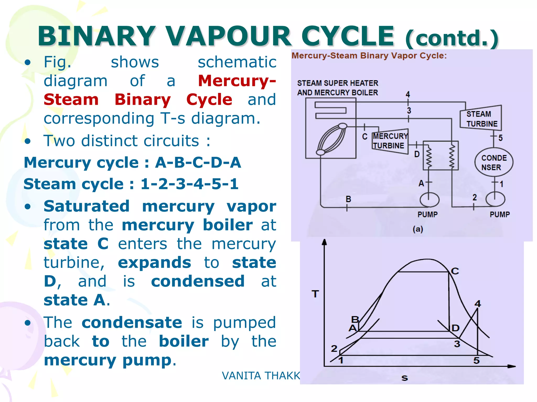
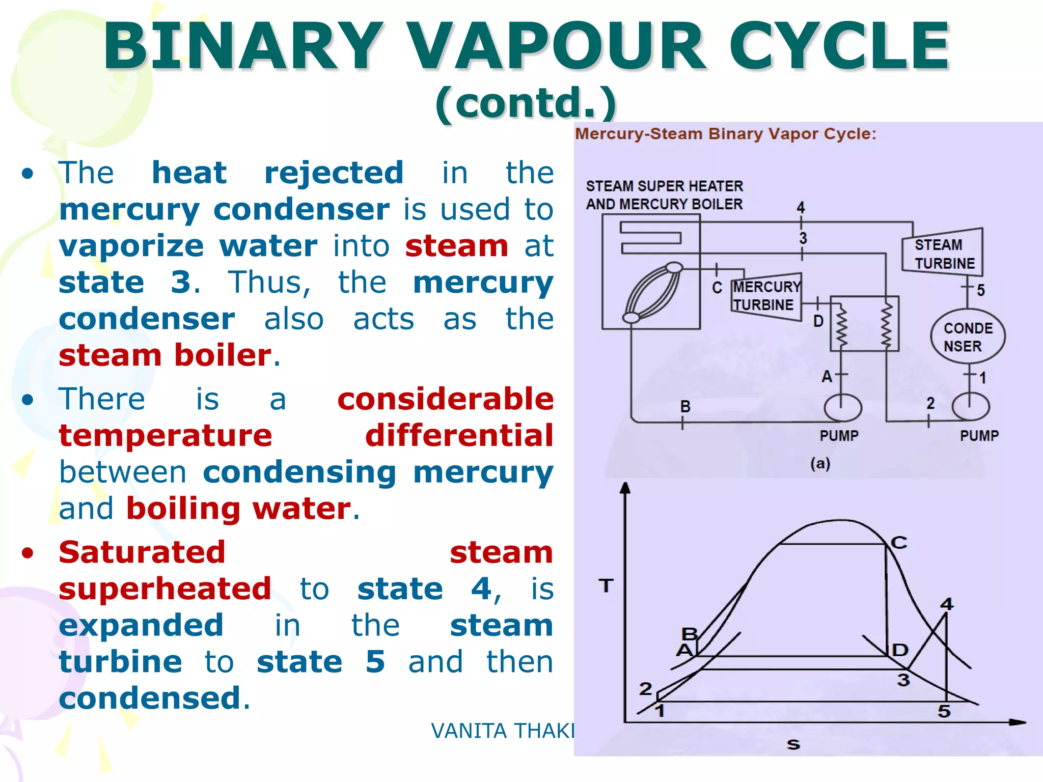
METHODS OF
IMPROVING
PERFORMANCE OF
STEAM TURBINES
- VANITA THAKKAR
ASSOCIATE PROFESSOR
MECHANICAL ENGINEERING DEPARTMENT,
BABARIA INSTITUTE OF TECHNOLOGY,
VARNAMA, VADODARA
CONTENTS
• INTRODUCTION
• CARNOT CYCLE
• LIMITATIONS OF CARNOT CYCLE
• IDEAL RANKINE CYCLE – MODIFICATION OF CARNOT
CYCLE
• IDEAL RANKINE CYCLE – USE OF SUPERHEATED STEAM
• ACTUAL RANKINE CYCLE
• RANKINE CYCLE WITH REHEAT
• OPTIMUM INTERMEDIATE PRESSURE AND TEMPERATURE
FOR REHEAT CYCLE
• REGENERATIVE FEED HEATING CYCLE
• BINARY VAPOUR CYCLE : Limitations of Steam, Ideal
Working Fluid for Rankine Cycle, Binary Vapour Cycle –
Hg-Steam Binary Vapour Cycle
VANITA THAKKAR 3
INTRODUCTION
• The highest
possible efficiency
in a power cycle
can be obtained if
the cycle consists of
only reversible
processes.
• Therefore, a Carnot
Cycle is most
appealing as a power
cycle.
VANITA THAKKAR 4
CARNOT CYCLE
• Consider the Carnot Cycle shown in
the figure.
• Wet steam at state 1 is
isentropically compressed to the
saturated liquid (state 2).
• The saturated liquid undergoes a
phase change of constant
temperature and pressure and
leaves the boiler as saturated
vapour (state 3).
• Then the saturated vapour is allowed
to expand isentropically in a
turbine and it leaves the turbine at
state 4.
• Finally this fluid is condensed to
state 1, thus completing the cycle.
VANITA THAKKAR 5
LIMITATIONS OF CARNOT
CYCLE
• Energy is added to the working fluid at
constant temperature T2 in boiler
and rejected at constant
temperature T1 in the condenser.
• The isentropic process 1-2 cannot
be practically achieved as it is
difficult to handle a two phase
mixture.
• Also, if the steam quality is poor, the
process 3-4 is difficult to carry out.
2 1
2
( )( )Net Work Done
Energy Supplied ( )
B A
B A
T T S S
T S S
− −
η =
−
1
2
1
T
T
η = −
VANITA THAKKAR 6
IDEAL RANKINE CYCLE –
MODIFICATION OF CARNOT CYCLE
• The isentropic
compression of wet
steam is replaced by
isentropic compression
of saturated liquid which
can be easily carried out
with the help of a pump.
• Figure shows the cyclic
representation of the
modified Carnot cycle –
Rankine Cycle.
VANITA THAKKAR 7
IDEAL RANKINE CYCLE (contd.)
• Energy Addition :
• Energy Rejection :
• Thermal Efficiency :
i.e., =
Since,
4 5 2 1
4 2
( ) ( )
( )
h h h h
h h
− − −
η =
−
VANITA THAKKAR 8
IDEAL RANKINE CYCLE – USE OF
SUPERHEATED STEAM
• It can be observed that the
isentropic expansion of the
steam continuously decreases
its quality when going from
state 4 to state 5.
• Presence of excessive moisture
content causes serious erosion
of turbine blades, which is
highly undesirable.
• To overcome this, modern steam
power plants produce
superheated steam which is fed
to turbine for subsequent
expansion.
VANITA THAKKAR 9
IDEAL RANKINE CYCLE – USE OF
SUPERHEATED STEAM (contd.)
operating between the same temperature
levels, since :
• Energy transfer as heat in boiler does
not take place at constant
temperature in the Rankine cycle.
• The average temperature between
the state 2 and 3 is less than the
temperature at which vaporization
take place.
• Particularly in the case of Rankine cycle
with superheat, the maximum
temperature corresponds to state 4
which is much above the temperature
of vaporization at which a major
fraction of the energy addition take
place.
thermal,Rankine thermal,Carnot<η η
VANITA THAKKAR 10
ACTUAL RANKINE CYCLE
• In actual practice, the pump and
the turbine cannot be operated
under isentropic condition because
of irreversibilities.
• Therefore process 1-2 and 4-5 are
non-isentropic.
• Applying the second law of
thermodynamics to the control
volumes turbine and pump it is
found that the entropy of the exit
fluid is greater than the entropy
of the entering fluid.
i.e. And
Also,
Therefore &
VANITA THAKKAR 11
ACTUAL RANKINE CYCLE (contd.)
• Actual work delivered
by turbine < Work
delivered by an
isentropic turbine.
• Work spent on actual
pump > Work spent on
isentropic pump.
• Due to
IRREVERSIBILTIES in
turbine and pump,
Actual Rankine Cycle Ideal Rankine Cycleη < η
VANITA THAKKAR 12
ACTUAL RANKINE CYCLE (contd.)
• The performance of an
actual turbine or pump is
usually expressed in terms of
isentropic efficiency.
• Efficiency of Actual Rankine
Cycle :
VANITA THAKKAR 13
RANKINE CYCLE WITH REHEAT
REHEATING : Splitting of Expansion process of
turbine to :
 Control DRYNESS FRACTION : x= 0.88 to
0.9 desirable to prevent erosion of turbine
blades.
 Get MORE OUTPUT for given maximum
temperature and pressure.
VANITA THAKKAR 14
RANKINE CYCLE WITH REHEAT
• Steam leaving boiler at state 4 enters the high- pressure section of
turbine where it expands to some intermediate pressure (shown in Figure).
• Then the steam leaves the turbine at state 5 and enters the boiler where
it is reheated.
• The reheating of the steam is usually done to the original temperature
of the steam.
• The reheated steam at stage 6 enters the low pressure section of the
turbine and expands to the condenser pressure.
• The wet steam at state 7 enters the condenser where it rejects heat to
the cooling water and leaves the condenser at state 1.
VANITA THAKKAR 15
RANKINE CYCLE WITH REHEAT (contd.)
Total Energy added in Boiler =
Energy Rejected in Condenser =
Thermal Efficiency =
= i.e.,
VANITA THAKKAR 16
OPTIMUM INTERMEDIATE PRESSURE AND
TEMPERATURE FOR REHEAT CYCLE
• Reheat Rankine cycle will perform efficiently when
intermediate pressure for reheating is optimized.
• First, the intermediate temperature is determined :
T5 = (h4 – h2)/(s4 – s2)
• Intermediate pressure, p5 = saturation pressure
corresponding to the above temperature, T5.
Generally, optimum p5 corresponds to (p5/p4) =
0.2 to 0.23
VANITA THAKKAR 17
MORE ABOUT RANKINE CYCLE WITH
REHEAT
More possibilities in Reheat
Cycle :
1.Wet steam at intermediate
pressure (p4, here),
2.Reheating to a temperature
less than the inlet temperature
of steam in the HP Turbine.
Generally for :
Pressure range – 100 to 250
bar;
Temperature range – 500 to
600oC,
ONE REHEAT CYCLE.
For higher steam conditions :
TWO REHEAT CYCLES.
VANITA THAKKAR 18
Thus, in
RANKINE CYCLE WITH REHEAT
• The effective temperature at which
energy is added is increased by
supplying a large portion of energy
in the superheat region.
VANITA THAKKAR 19
REGENERATIVE FEED HEATING
CYCLE
• In Simple Rankine Cycle, condensate at low
temperature mixes irreversibly with hot boiler
water and there is decrease in cycle efficiency.
• Irreversible heating of feed water going from
hot well of condenser to boiler is done by using
the heat within the system to improve cycle
efficiency.
• The average temperature at which energy
addition takes place is increased by
preheating the feed water before it enters the
boiler
• A Rankine cycle using this type of feed water
heating is called a REGENERATIVE CYCLE.
VANITA THAKKAR 20
REGENERATIVE FEED HEATING
CYCLE : PRINCIPLE
PRINCIPLE OF REGENERATION :
Extracting steam from Turbine at
various locations and supplying it
to Regenerative Feed Heaters.
The extracted steam is also called
Bled steam.
For MEDIUM CAPACITY TURBINES
(pr. Upto about 40 bar) : Not more
than 3 heaters.
For HIGH PRESSURE, HIGH
CAPACITY TURBINES (pressure
between 40 to 120 bar) : 5 to 7
heaters.
For Turbines with supercritical
parameters : 8 to 9 heaters.
VANITA THAKKAR 21
REGENERATIVE FEED HEATING
CYCLE : PRINCIPLE
The most advantageous condensate heating
temperatures are selected, depending upon
turbine throttle conditions. This determines the
no. of heaters to be used.
The final condensate heating temperature is
kept 50oC to 60oC below the boiler saturated
steam temperature to prevent evaporation of
water in the feed mains, which leads to drop in
boiler drum pressure.
The conditions of the steam bled for each heater
are so selected that the temperature of
saturated steam will be 4oC to 10oC higher
than the final condensate temperature.
VANITA THAKKAR 22
REGENERATIVE FEED HEATING
CYCLE WITH ONE FEED HEATER :
Fig. shows A regenerative cycle having a
single stage of feed water heating
Steam enters the turbine at state 5.
After expansion to state 6, part of this
steam is extracted and supplied to the
feed water heater while the remainder
continues to expand to state 7.
Let m1 = mass of steam extracted at
state 6
then, heat balance for heater gives,
VANITA THAKKAR 23
REGENERATIVE FEED HEATING
CYCLE WITH ONE FEED HEATER
(contd.)
THERMAL EFFICIENCY :
VANITA THAKKAR 24
REGENERATIVE FEED HEATING
CYCLE WITH TWO OR MORE FEED
HEATERS
SIMILARLY THE DERIVATIONS FOR TWO OR MORE
FEED WATER HEATERS USED IN REGENERATIVE
FEED HEATING CYCLES.
TO BE DONE :
DERIVATION FOR FINDING THE MASS OF
BLED STEAM FOR REGERATIVE FEED
HEATING CYCLE USING TWO FEED HEATERS
VANITA THAKKAR 25
BINARY VAPOUR CYCLE :
Introduction
Thermal efficiency of Rankine
cycle can be increased by:
1) Increasing the average
temperature of heat addition.
2) Decreasing the average
temperature of heat
rejection.
VANITA THAKKAR 26
BINARY VAPOUR CYCLE :
Limitations of Steam
Maximum temperature of the cycle is limited by
practical considerations. For steam as a
working fluid, the following difficulties arise at
maximum temperature.
1) Critical temperature of steam is equal to
3740C and critical pressure is 221.2 bar. It is
not possible to work at this pressure.
2) Latent heat of vaporization decreases as
the pressure increases.
3) If high pressure steam is expanded, high
degree of moisture content will be present at
the end of process.
VANITA THAKKAR 27
BINARY VAPOUR CYCLE : Ideal
Working Fluid for Rankine Cycle
The minimum temperature of the cycle is usually limited to
natural water temperature of 250C. At this temperature,
the saturation pressure of water will be 0.0318 bar. It
means that the condenser has to work at vacuum. This is
very difficult.
So, ideal working fluid for Rankine cycle should fulfill the
following requirements :
1) Reasonable saturation pressure at maximum
temperature.
2) Steep saturated vapor line to minimize moisture
problem.
3) Saturation pressure higher than atmospheric at
minimum temperature.
4) Low liquid specific heat so that most of the heat is
added at maximum temperature.
5) Non-toxic and non-corrosive.
VANITA THAKKAR 28
BINARY VAPOUR CYCLE (contd.)
All these requirements are not met by any
single working fluid.
In BINARY VAPOUR CYCLE, two working
fluids are used in combination, to utilize
the desirable features of each fluid and
hence, obtain good results.
Mercury and Steam are most commonly used
working fluids.
Saturation Pressure and Saturation
Temperature of mercury is 20.6 bar and
5400C at Critical Point.
VANITA THAKKAR 29
BINARY VAPOUR CYCLE (contd.)
• Fig. shows schematic
diagram of a Mercury-
Steam Binary Cycle and
corresponding T-s diagram.
• Two distinct circuits :
Mercury cycle : A-B-C-D-A
Steam cycle : 1-2-3-4-5-1
• Saturated mercury vapor
from the mercury boiler at
state C enters the mercury
turbine, expands to state
D, and is condensed at
state A.
• The condensate is pumped
back to the boiler by the
mercury pump.
VANITA THAKKAR 30
BINARY VAPOUR CYCLE
(contd.)
• The heat rejected in the
mercury condenser is used to
vaporize water into steam at
state 3. Thus, the mercury
condenser also acts as the
steam boiler.
• There is a considerable
temperature differential
between condensing mercury
and boiling water.
• Saturated steam
superheated to state 4, is
expanded in the steam
turbine to state 5 and then
condensed.
VANITA THAKKAR 31
BINARY VAPOUR CYCLE
(contd.)
VANITA THAKKAR 32
THANKS !!
- VANITA THAKKAR
ASSOCIATE PROFESSOR
MECHANICAL ENGINEERING DEPARTMENT,
BABARIA INSTITUTE OF TECHNOLOGY,
VARNAMA, VADODARA

METHODS OF IMPROVING STEAM TURBINE PERFORMANCE

  • 1.
    METHODS OF IMPROVING PERFORMANCE OF STEAMTURBINES - VANITA THAKKAR ASSOCIATE PROFESSOR MECHANICAL ENGINEERING DEPARTMENT, BABARIA INSTITUTE OF TECHNOLOGY, VARNAMA, VADODARA
  • 2.
    CONTENTS • INTRODUCTION • CARNOTCYCLE • LIMITATIONS OF CARNOT CYCLE • IDEAL RANKINE CYCLE – MODIFICATION OF CARNOT CYCLE • IDEAL RANKINE CYCLE – USE OF SUPERHEATED STEAM • ACTUAL RANKINE CYCLE • RANKINE CYCLE WITH REHEAT • OPTIMUM INTERMEDIATE PRESSURE AND TEMPERATURE FOR REHEAT CYCLE • REGENERATIVE FEED HEATING CYCLE • BINARY VAPOUR CYCLE : Limitations of Steam, Ideal Working Fluid for Rankine Cycle, Binary Vapour Cycle – Hg-Steam Binary Vapour Cycle
  • 3.
    VANITA THAKKAR 3 INTRODUCTION •The highest possible efficiency in a power cycle can be obtained if the cycle consists of only reversible processes. • Therefore, a Carnot Cycle is most appealing as a power cycle.
  • 4.
    VANITA THAKKAR 4 CARNOTCYCLE • Consider the Carnot Cycle shown in the figure. • Wet steam at state 1 is isentropically compressed to the saturated liquid (state 2). • The saturated liquid undergoes a phase change of constant temperature and pressure and leaves the boiler as saturated vapour (state 3). • Then the saturated vapour is allowed to expand isentropically in a turbine and it leaves the turbine at state 4. • Finally this fluid is condensed to state 1, thus completing the cycle.
  • 5.
    VANITA THAKKAR 5 LIMITATIONSOF CARNOT CYCLE • Energy is added to the working fluid at constant temperature T2 in boiler and rejected at constant temperature T1 in the condenser. • The isentropic process 1-2 cannot be practically achieved as it is difficult to handle a two phase mixture. • Also, if the steam quality is poor, the process 3-4 is difficult to carry out. 2 1 2 ( )( )Net Work Done Energy Supplied ( ) B A B A T T S S T S S − − η = − 1 2 1 T T η = −
  • 6.
    VANITA THAKKAR 6 IDEALRANKINE CYCLE – MODIFICATION OF CARNOT CYCLE • The isentropic compression of wet steam is replaced by isentropic compression of saturated liquid which can be easily carried out with the help of a pump. • Figure shows the cyclic representation of the modified Carnot cycle – Rankine Cycle.
  • 7.
    VANITA THAKKAR 7 IDEALRANKINE CYCLE (contd.) • Energy Addition : • Energy Rejection : • Thermal Efficiency : i.e., = Since, 4 5 2 1 4 2 ( ) ( ) ( ) h h h h h h − − − η = −
  • 8.
    VANITA THAKKAR 8 IDEALRANKINE CYCLE – USE OF SUPERHEATED STEAM • It can be observed that the isentropic expansion of the steam continuously decreases its quality when going from state 4 to state 5. • Presence of excessive moisture content causes serious erosion of turbine blades, which is highly undesirable. • To overcome this, modern steam power plants produce superheated steam which is fed to turbine for subsequent expansion.
  • 9.
    VANITA THAKKAR 9 IDEALRANKINE CYCLE – USE OF SUPERHEATED STEAM (contd.) operating between the same temperature levels, since : • Energy transfer as heat in boiler does not take place at constant temperature in the Rankine cycle. • The average temperature between the state 2 and 3 is less than the temperature at which vaporization take place. • Particularly in the case of Rankine cycle with superheat, the maximum temperature corresponds to state 4 which is much above the temperature of vaporization at which a major fraction of the energy addition take place. thermal,Rankine thermal,Carnot<η η
  • 10.
    VANITA THAKKAR 10 ACTUALRANKINE CYCLE • In actual practice, the pump and the turbine cannot be operated under isentropic condition because of irreversibilities. • Therefore process 1-2 and 4-5 are non-isentropic. • Applying the second law of thermodynamics to the control volumes turbine and pump it is found that the entropy of the exit fluid is greater than the entropy of the entering fluid. i.e. And Also, Therefore &
  • 11.
    VANITA THAKKAR 11 ACTUALRANKINE CYCLE (contd.) • Actual work delivered by turbine < Work delivered by an isentropic turbine. • Work spent on actual pump > Work spent on isentropic pump. • Due to IRREVERSIBILTIES in turbine and pump, Actual Rankine Cycle Ideal Rankine Cycleη < η
  • 12.
    VANITA THAKKAR 12 ACTUALRANKINE CYCLE (contd.) • The performance of an actual turbine or pump is usually expressed in terms of isentropic efficiency. • Efficiency of Actual Rankine Cycle :
  • 13.
    VANITA THAKKAR 13 RANKINECYCLE WITH REHEAT REHEATING : Splitting of Expansion process of turbine to :  Control DRYNESS FRACTION : x= 0.88 to 0.9 desirable to prevent erosion of turbine blades.  Get MORE OUTPUT for given maximum temperature and pressure.
  • 14.
    VANITA THAKKAR 14 RANKINECYCLE WITH REHEAT • Steam leaving boiler at state 4 enters the high- pressure section of turbine where it expands to some intermediate pressure (shown in Figure). • Then the steam leaves the turbine at state 5 and enters the boiler where it is reheated. • The reheating of the steam is usually done to the original temperature of the steam. • The reheated steam at stage 6 enters the low pressure section of the turbine and expands to the condenser pressure. • The wet steam at state 7 enters the condenser where it rejects heat to the cooling water and leaves the condenser at state 1.
  • 15.
    VANITA THAKKAR 15 RANKINECYCLE WITH REHEAT (contd.) Total Energy added in Boiler = Energy Rejected in Condenser = Thermal Efficiency = = i.e.,
  • 16.
    VANITA THAKKAR 16 OPTIMUMINTERMEDIATE PRESSURE AND TEMPERATURE FOR REHEAT CYCLE • Reheat Rankine cycle will perform efficiently when intermediate pressure for reheating is optimized. • First, the intermediate temperature is determined : T5 = (h4 – h2)/(s4 – s2) • Intermediate pressure, p5 = saturation pressure corresponding to the above temperature, T5. Generally, optimum p5 corresponds to (p5/p4) = 0.2 to 0.23
  • 17.
    VANITA THAKKAR 17 MOREABOUT RANKINE CYCLE WITH REHEAT More possibilities in Reheat Cycle : 1.Wet steam at intermediate pressure (p4, here), 2.Reheating to a temperature less than the inlet temperature of steam in the HP Turbine. Generally for : Pressure range – 100 to 250 bar; Temperature range – 500 to 600oC, ONE REHEAT CYCLE. For higher steam conditions : TWO REHEAT CYCLES.
  • 18.
    VANITA THAKKAR 18 Thus,in RANKINE CYCLE WITH REHEAT • The effective temperature at which energy is added is increased by supplying a large portion of energy in the superheat region.
  • 19.
    VANITA THAKKAR 19 REGENERATIVEFEED HEATING CYCLE • In Simple Rankine Cycle, condensate at low temperature mixes irreversibly with hot boiler water and there is decrease in cycle efficiency. • Irreversible heating of feed water going from hot well of condenser to boiler is done by using the heat within the system to improve cycle efficiency. • The average temperature at which energy addition takes place is increased by preheating the feed water before it enters the boiler • A Rankine cycle using this type of feed water heating is called a REGENERATIVE CYCLE.
  • 20.
    VANITA THAKKAR 20 REGENERATIVEFEED HEATING CYCLE : PRINCIPLE PRINCIPLE OF REGENERATION : Extracting steam from Turbine at various locations and supplying it to Regenerative Feed Heaters. The extracted steam is also called Bled steam. For MEDIUM CAPACITY TURBINES (pr. Upto about 40 bar) : Not more than 3 heaters. For HIGH PRESSURE, HIGH CAPACITY TURBINES (pressure between 40 to 120 bar) : 5 to 7 heaters. For Turbines with supercritical parameters : 8 to 9 heaters.
  • 21.
    VANITA THAKKAR 21 REGENERATIVEFEED HEATING CYCLE : PRINCIPLE The most advantageous condensate heating temperatures are selected, depending upon turbine throttle conditions. This determines the no. of heaters to be used. The final condensate heating temperature is kept 50oC to 60oC below the boiler saturated steam temperature to prevent evaporation of water in the feed mains, which leads to drop in boiler drum pressure. The conditions of the steam bled for each heater are so selected that the temperature of saturated steam will be 4oC to 10oC higher than the final condensate temperature.
  • 22.
    VANITA THAKKAR 22 REGENERATIVEFEED HEATING CYCLE WITH ONE FEED HEATER : Fig. shows A regenerative cycle having a single stage of feed water heating Steam enters the turbine at state 5. After expansion to state 6, part of this steam is extracted and supplied to the feed water heater while the remainder continues to expand to state 7. Let m1 = mass of steam extracted at state 6 then, heat balance for heater gives,
  • 23.
    VANITA THAKKAR 23 REGENERATIVEFEED HEATING CYCLE WITH ONE FEED HEATER (contd.) THERMAL EFFICIENCY :
  • 24.
    VANITA THAKKAR 24 REGENERATIVEFEED HEATING CYCLE WITH TWO OR MORE FEED HEATERS SIMILARLY THE DERIVATIONS FOR TWO OR MORE FEED WATER HEATERS USED IN REGENERATIVE FEED HEATING CYCLES. TO BE DONE : DERIVATION FOR FINDING THE MASS OF BLED STEAM FOR REGERATIVE FEED HEATING CYCLE USING TWO FEED HEATERS
  • 25.
    VANITA THAKKAR 25 BINARYVAPOUR CYCLE : Introduction Thermal efficiency of Rankine cycle can be increased by: 1) Increasing the average temperature of heat addition. 2) Decreasing the average temperature of heat rejection.
  • 26.
    VANITA THAKKAR 26 BINARYVAPOUR CYCLE : Limitations of Steam Maximum temperature of the cycle is limited by practical considerations. For steam as a working fluid, the following difficulties arise at maximum temperature. 1) Critical temperature of steam is equal to 3740C and critical pressure is 221.2 bar. It is not possible to work at this pressure. 2) Latent heat of vaporization decreases as the pressure increases. 3) If high pressure steam is expanded, high degree of moisture content will be present at the end of process.
  • 27.
    VANITA THAKKAR 27 BINARYVAPOUR CYCLE : Ideal Working Fluid for Rankine Cycle The minimum temperature of the cycle is usually limited to natural water temperature of 250C. At this temperature, the saturation pressure of water will be 0.0318 bar. It means that the condenser has to work at vacuum. This is very difficult. So, ideal working fluid for Rankine cycle should fulfill the following requirements : 1) Reasonable saturation pressure at maximum temperature. 2) Steep saturated vapor line to minimize moisture problem. 3) Saturation pressure higher than atmospheric at minimum temperature. 4) Low liquid specific heat so that most of the heat is added at maximum temperature. 5) Non-toxic and non-corrosive.
  • 28.
    VANITA THAKKAR 28 BINARYVAPOUR CYCLE (contd.) All these requirements are not met by any single working fluid. In BINARY VAPOUR CYCLE, two working fluids are used in combination, to utilize the desirable features of each fluid and hence, obtain good results. Mercury and Steam are most commonly used working fluids. Saturation Pressure and Saturation Temperature of mercury is 20.6 bar and 5400C at Critical Point.
  • 29.
    VANITA THAKKAR 29 BINARYVAPOUR CYCLE (contd.) • Fig. shows schematic diagram of a Mercury- Steam Binary Cycle and corresponding T-s diagram. • Two distinct circuits : Mercury cycle : A-B-C-D-A Steam cycle : 1-2-3-4-5-1 • Saturated mercury vapor from the mercury boiler at state C enters the mercury turbine, expands to state D, and is condensed at state A. • The condensate is pumped back to the boiler by the mercury pump.
  • 30.
    VANITA THAKKAR 30 BINARYVAPOUR CYCLE (contd.) • The heat rejected in the mercury condenser is used to vaporize water into steam at state 3. Thus, the mercury condenser also acts as the steam boiler. • There is a considerable temperature differential between condensing mercury and boiling water. • Saturated steam superheated to state 4, is expanded in the steam turbine to state 5 and then condensed.
  • 31.
    VANITA THAKKAR 31 BINARYVAPOUR CYCLE (contd.)
  • 32.
    VANITA THAKKAR 32 THANKS!! - VANITA THAKKAR ASSOCIATE PROFESSOR MECHANICAL ENGINEERING DEPARTMENT, BABARIA INSTITUTE OF TECHNOLOGY, VARNAMA, VADODARA