Downloaded 13 times


![IES-1000 User’s Guide
Preface
Congratulations on your purchase of the IES-1000 Integrated Ethernet Switch.
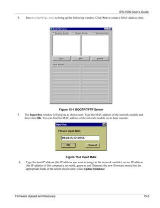
Online Registration
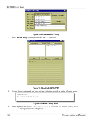
Register your ZyXEL product online at www.zyxel.com for free future product updates and information.
General Syntax Conventions
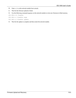
“Enter” means for you to type one or more characters and press the carriage return. “Select” or “Choose” means
for you to use one of the predefined choices.
Command and arrow keys are enclosed in square brackets. [ENTER] means the Enter, or carriage return key;
[ESC] means the Escape key and [SPACE BAR] means the Space Bar.
For brevity’s sake, we will use “e.g.,” as shorthand for “for instance”, and “i.e.,” for “that is” or “in other words”
throughout this User’s Guide.
There is one version of the AAM1008 for ADSL over POTS (Annex A) and one for ADSL over ISDN (Annex B).
Differentiation is made where needed.
Related Documentation
Quick Start Guide
The Quick Start Guide contains general initial configuration instructions.
Hardware Installation Guide
This guide provides detailed information about the physical specifications and procedures for installing
your device.
Web Configurator Online Help
Embedded web help for descriptions of individual screens and supplementary information.
Glossary and ZyXEL Web Site
Please refer to www.zyxel.com for an online glossary of networking terms or the ZyXEL download
library for additional support documentation.
Preface xiii](https://image.slidesharecdn.com/ies-1000v204usersguide-110321234330-phpapp02/85/Ies-1000-v2-04_users_guide-13-320.jpg)


![IES-1000 User’s Guide
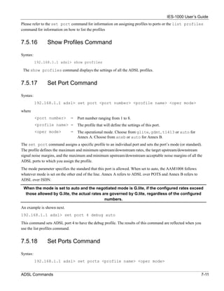
Chapter 5
System Commands
This section describes basic configuration and system-related commands.
5.1 Command Line Interface (CI)
The IES-1000 uses text command lines as the user interface for software configuration. Before discussing the
details of configuration, the rules of the commands are listed next.
The command keywords are in courier new font.
1. The command keywords must be entered exactly as shown, that is, no abbreviations are allowed.
2. The required fields in a command are enclosed in angle brackets (<>), for instance,
list port <port #>
means that you must specify the port number for this command.
3. The optional fields in a command are enclosed in square brackets ([]), for instance,
config [save]
means that the save field is optional.
4. A “|” means “or”
[on|off]
means that you can use either on or off.
5. “Command” refers to a command used in the command line interface (CI command).
Using commands not documented in this User’s Guide can damage the unit and possibly render
it unusable.
5.2 Console Connection
For the initial configuration, you must use the console port. After the initial setup, you can telnet to the system and
perform additional management tasks. Connect the RJ-11 connector on one end of the RS-232 console cable to the
console port of the network module. Connect the DB-9 connector on the other end of the console cable to a serial
port (COM1, COM2 or other COM port) of your computer. You can use an extension cable if the enclosed one is
too short. After the initial setup, you can modify the configuration remotely through Telnet
You can use any terminal emulation program (Windows’ built-in HyperTerminal for example) with the following
parameters:
• VT100 terminal emulation
• 9600 bps
System Commands 5-1](https://image.slidesharecdn.com/ies-1000v204usersguide-110321234330-phpapp02/85/Ies-1000-v2-04_users_guide-31-320.jpg)
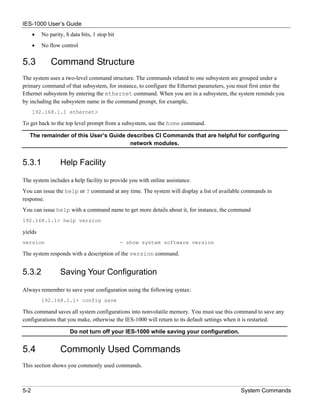
![IES-1000 User’s Guide
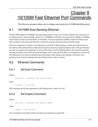
5.4.6 Exit Command
Syntax:
192.168.1.1> exit
This command terminates the console or telnet management session.
5.5 Sys Commands
5.5.1 Info Command
Syntax:
192.168.1.1 sys> info
This command displays system related information.
5.5.2 Set Name Command
Syntax:
192.168.1.1 sys> set name <name>
This command allows you to set the name of your IES-1000. The previous setting will be cleared if the command
is entered with the <name> parameter omitted.
5.5.3 Set Contact Command
Syntax:
192.168.1.1 sys> set contact [<name>]
This command allows you to set the name of the contact person for your IES-1000. The previous setting will be
cleared if the command is entered with the name omitted.
5.5.4 Set Location Command
Syntax:
192.168.1.1 sys> set location [<name>]
This command allows you to set the location of your IES-1000. The previous setting will be cleared if the
command is entered with the location omitted.
5-4 System Commands](https://image.slidesharecdn.com/ies-1000v204usersguide-110321234330-phpapp02/85/Ies-1000-v2-04_users_guide-34-320.jpg)
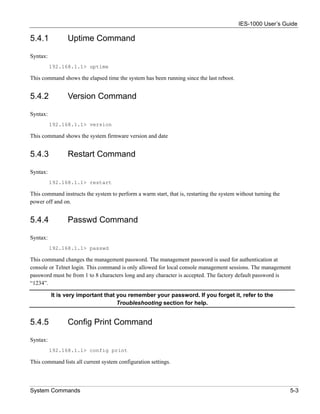
![IES-1000 User’s Guide
5.5.5 Set Mode Command
Syntax:
192.168.1.1 sys> set mode [fast|normal]
where
fast = Fast makes use of the “tag” subset of the IEEE 802.1Q standard to identify the
source port of a frame and speed traffic through a service gateway.
normal = Normal switches frames using a layer 2 switch (IEEE 801.1D) transparent
bridge standard. Use normal mode when you are using a regular gateway.
This command lets you set the network module into fast or normal mode. Determine which mode you are
using by entering the info command. Fast mode allows only one port per PVID. Use normal mode and the
802.1Q VLAN commands (see Chapter 10 ) to configure VLANs or PVIDs with multiple ports.
Enable fast mode only when you are using a service gateway.
5.6 Secured Host Commands
Allow up to ten remote administrators to access your IES-1000 via IP addresses you specify.
5.6.1 Secured Host Command
Syntax:
192.168.1.1 sys> secured host [<mode>]
where
<mode> = "enable" or "disable".
If <mode>= disable (default), then anyone may access your IES-1000.
If <mode>= enable, then only those computers with IP addresses specified by
you may access your IES-1000 (refer to the Secured Host Add command).
This command enables/disables the secured host function. To display current secured host settings, simply
enter the command secured host.
5.6.2 Secured Host Add Command
Syntax:
192.168.1.1 sys> secured host add <host IP>
where
<host IP> = The IP address of a secured host.
This command adds the IP address of a secured host. You may add up to ten IP addresses.
System Commands 5-5](https://image.slidesharecdn.com/ies-1000v204usersguide-110321234330-phpapp02/85/Ies-1000-v2-04_users_guide-35-320.jpg)
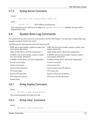
![IES-1000 User’s Guide
5.6.3 Secured Host Delete Command
Syntax:
192.168.1.1 sys> secured host delete <host IP>
where
<host IP> = The IP address of a secured host.
This command deletes the IP address of a previously added secured host.
5.7 UNIX Syslog Commands
Use UNIX syslog commands to send logs to your UNIX server. If the DSL link is on or goes down, the IES-1000
will send a log to your UNIX server. The table, shown next, indicates what is logged in each case.
Table 5-1 Logs Sent to Your UNIX Server
DSL LINK ON DSL LINK DOWN
port number port number
sequence number sequence number
rate -
If your UNIX server is down these logs will be lost.
5.7.1 Syslog Command
Syntax:
192.168.1.1 sys> syslog [<mode>]
where
<mode> = enable or disable.
This command enables or disables the sending of logs to your UNIX server. Syslog is disabled by default
(<mode>= disable). A log is sent if <mode>= enable. To display current settings, do not specify a
<mode>.
5.7.2 Syslog Facility Command
Syntax:
192.168.1.1 sys> syslog facility <facility>
where
<facility> = Local 1 to local 7.
This command sets the syslog facility for the UNIX system.
5-6 System Commands](https://image.slidesharecdn.com/ies-1000v204usersguide-110321234330-phpapp02/85/Ies-1000-v2-04_users_guide-36-320.jpg)
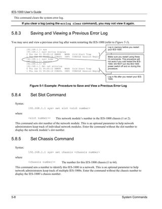
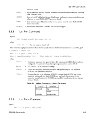
![IES-1000 User’s Guide
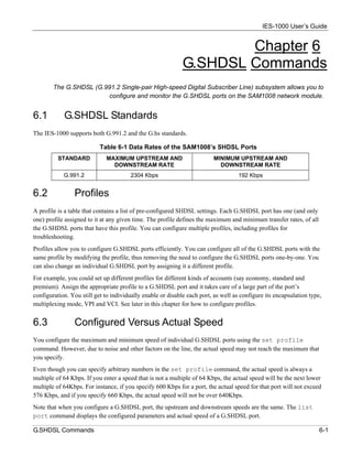
This command shows the configured minimum speeds (if applicable), maximum speeds, states and statuses of all
G.SHDSL ports. Here is a description of the various status field messages:
Failed = The system was unable to download firmware to the DSL chipset.
Dropped = The port is a member of a bonded group but was dropped because it could not connect
within at least 640 Kbps of the rate of the other bonded ports. Both the central and remote
sides of the connection must disable and re-enable the dropped port to attempt to bring up
the connection again.
BondC = The port is connected and functioning as part of a central side group of bonded ports. See
the Set Central Side Port Bonding Command section.
BondR = The port is connected and functioning as part of remote side group of bonded ports. See
the Set Remote Side Port Bonding Command section.
Normal = The port is connected and functioning as a regular (non-bonded) G.SHDSL port.
6.6.10 Set Profile Command
Syntax:
192.168.1.1 gshdsl> set profile <name> <Cmax> [<Cmin>]
where
<name> = The name of the profile (up to 18 characters except DEFVAL).
<Cmax> = The maximum transmission rate in Kbps.
<Cmin> = The minimum transmission rate in Kbps. This setting is optional. 192 Kbps is the
default if you do not configure a value for this parameter. Setting Cmax and Cmin to
the same rate fixes the rate for that port.
Configure <Cmax> and <Cmin> parameters between 192 and 2304 Kbps.
Speed Configuration
Even though you can specify arbitrary numbers for port speeds using the set profile command, the
SAM1008 port speed is always adjusted to be a multiple of 64 Kbps. If you enter a speed that is not a multiple of
64 Kbps, the SAM1008 will use the next lower multiple of 64 Kbps. For instance, if you specify 600 Kbps for a
port, the SAM1008 port will not exceed 576 Kbps; if you specify 660 Kbps, the SAM1008 port will not exceed
640 Kbps. See the examples shown next.
Example 1:
The configuration
192.168.1.1 gshdsl> set profile economy 2000 200
sets the speed for the economy profile between 1984 and 192 Kbps.
6-6 G.SHDSL Commands](https://image.slidesharecdn.com/ies-1000v204usersguide-110321234330-phpapp02/85/Ies-1000-v2-04_users_guide-44-320.jpg)
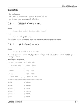
![IES-1000 User’s Guide
6.6.16 Set Ports Command
Syntax:
192.168.1.1 gshdsl> set ports <profile name>
where
<profile name> = The profile that defines the minimum and maximum transfer rates for this
port.
This CI command is like the Set Port Command described in section 6.6.15 except that this command
configures all G.SHDSL ports to have a specified profile. Enter the list ports command to view the status
of all ports.
6.6.17 Set PVC Command
Syntax:
192.168.1.1 gshdsl> set pvc <port #> <multiplexing mode> <tx vpi> <tx vci>
[<rx vpi> <rx vci>]
where
<port #> = A port number, from 1 to 8.
<multiplexing mode> = Either “llc” or “vc"
<tx vpi> = The VPI setting of the G.SHDSL port for use with a TX based
network.
<tx vci> = The VCI setting for the G.SHDSL port for use with a TX based
network.
<rx vpi> = The VPI setting for the G.SHDSL port for use with Rx based
networks.
<rx vci> = The VCI setting for the G.SHDSL port for use with Rx based
networks.
The <rx vpi> and <rx vci> settings will be equal to those of <tx vpi> and <tx vci> if the rx
settings are not configured.
The set pvc command allows the configuration of a PVC (permanent virtual circuit) for an individual
G.SHDSL port.
6.6.18 Set PVCs Command
Syntax:
192.168.1.1 gshdsl> set pvcs <multiplexing mode> <tx vpi> <tx vci> [<rx
vpi> <rx vci>]
where
<multiplexing mode>= Either “llc” or “vc”.
<tx vpi> = The VPI setting of the G.SHDSL ports for use with a TX based
network.
G.SHDSL Commands 6-9](https://image.slidesharecdn.com/ies-1000v204usersguide-110321234330-phpapp02/85/Ies-1000-v2-04_users_guide-47-320.jpg)
![IES-1000 User’s Guide
<tx vci> = The VCI setting for the G.SHDSL ports for use with a TX based
network.
<rx vpi> = The VPI setting for the G.SHDSL ports for use with Rx based
networks.
<rx vpi> = The VCI setting for the G.SHDSL ports for use with Rx based
networks.
The <rx vpi> and <rx vci> settings will be equal to those of <tx vpi> and <tx vci> if the rx
settings are not configured.
The set pvcs command allows you to configure a single PVC for all of the G.SHDSL ports at once.
6.6.19 Show PVC Command
Syntax:
192.168.1.1 gshdsl> show pvc <port #>
where
<port #> = A port number, from 1 to 8.
This command allows you to display the PVC parameters of an individual G.SHDSL port
6.6.20 Show PVCs Command
Syntax:
192.168.1.1 gshdsl> show pvcs
This command allows you to display the PVC parameters of all G.SHDSL ports.
6.6.21 Display All G.SHDSL Line Information
Syntax:
192.168.1.1 gshdsl> monitor [<start port> [<stop port>]]
where
<start port> = The first port number in a range of ports for which you want to display
line information. 1 is used if you leave this blank.
<stop port> = The last port number in a range of ports for which you want to display
line information. 8 is used if you leave this blank.
This command displays all G.SHDSL line information. Information is updated every five seconds. Press any
key and then press [ENTER] to stop updating information. Use monitor without any port numbers to display
line information for every port.
6.6.22 Set Central Side Port Bonding Command
Syntax:
6-10 G.SHDSL Commands](https://image.slidesharecdn.com/ies-1000v204usersguide-110321234330-phpapp02/85/Ies-1000-v2-04_users_guide-48-320.jpg)
![IES-1000 User’s Guide
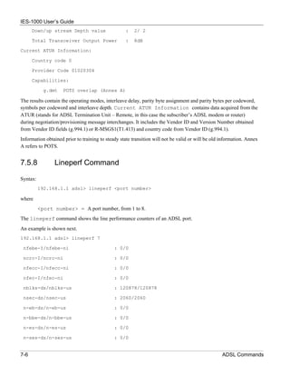
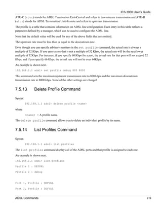
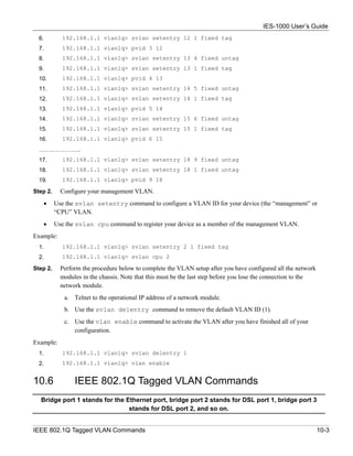
7.5.10 List Port Command
Syntax:
192.168.1.1 adsl> list port <port number>
where
<port number> = A port number, from 1 to 8.
The list port command shows the configured maximum upstream/downstream rates, the mode (or standard),
and enable/disable state of an individual ADSL port.
7.5.11 List Ports Command
Syntax:
192.168.1.1 adsl> list ports
The list ports command shows the configured maximum rates, modes and states of all ADSL ports.
7.5.12 Set Profile Command
Syntax:
192.168.1.1 adsl> set profile <name> <atur max rate > <atuc max rate> [<atur
...> <atuc ...>]
<atux ...> = <target margin> <min margin> <max margin> <min rate>
where
<name> = The name of the profile (up to 32 characters).
<atur max rate> = The maximum ADSL upstream transmission rate.
<atuc max rate> = The maximum ADSL downstream transmission rate.
<atur target margin> = The target ADSL upstream signal/noise margin (0-31db).
<atuc target margin> = The target ADSL downstream signal/noise margin (0-31db).
<atur min margin> = The minimum acceptable ADSL upstream signal/noise margin (0-
31db).
<atuc min margin> = The minimum acceptable ADSL downstream signal/noise margin (0-
31db).
<atur max margin> = The maximum acceptable ADSL upstream signal/noise margin (0-
31db).
<atuc max margin> = The maximum acceptable ADSL downstream signal/noise margin (0-
31db).
<atur min rate> = The minimum ADSL upstream transmission rate in Kbps.
<atuc min rate> = The minimum ADSL downstream transmission rate in Kbps.
7-8 ADSL Commands](https://image.slidesharecdn.com/ies-1000v204usersguide-110321234330-phpapp02/85/Ies-1000-v2-04_users_guide-58-320.jpg)
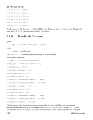
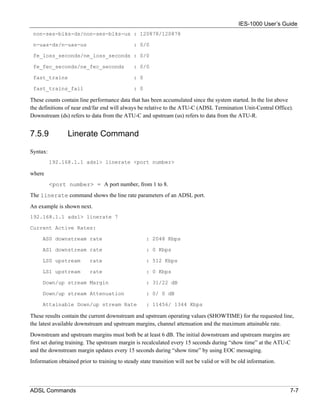
![IES-1000 User’s Guide
where
<profile name> = The profile that will define the settings of this port.
<oper mode> = Operational mode. Choose from glite, gdmt, t1413 or auto for Annex
A. Choose from anxb or auto for Annex B.
The set ports command assigns a specific profile to all of the ADSL ports and sets all of the ports to one
mode, or standard. The profile defines the maximum and minimum upstream/downstream rates, the target
upstream/downstream signal noise margins, and the maximum and minimum upstream/downstream acceptable
noise margins of all the ADSL ports.
The mode parameter specifies the standard that this port is allowed. When set to auto, the AAM1008 follows
whatever mode is set on the other end of the line.
When the mode is set to auto and the negotiated mode is G.lite, if the configured rates exceed
those allowed by G.lite, the actual rates are governed by G.lite, regardless of the configured
numbers.
7.5.19 Show Port Command
Syntax:
show port <port number>
where
<port number> = A port number, from 1 to 8.
The show port command shows the line status (up or down), the actual upstream/downstream rates and mode of
an individual ADSL port.
7.5.20 Show Ports Command
Syntax:
192.168.1.1 adsl> show ports
The show ports command shows the line status (up or down), the actual upstream/downstream rates and the
mode of all ADSL ports.
7.5.21 Set PVC Command
Syntax:
192.168.1.1 adsl> set pvc <port number> <multiplexing mode> <tx vpi>
<tx vci> [<rx vpi> <rx vci>]
where
<port number> = A port number, from 1 to 8.
7-12 ADSL Commands](https://image.slidesharecdn.com/ies-1000v204usersguide-110321234330-phpapp02/85/Ies-1000-v2-04_users_guide-62-320.jpg)
![IES-1000 User’s Guide
<multiplexing mode> = Either “llc” or “vc"
<tx vpi> = The VPI setting of the ADSL port for use with a Tx based network
<tx vci> = The VCI setting for the ADSL port for use with a Tx based network
<rx vpi> = The VPI setting for the ADSL port for use with Rx based networks
<rx vci> = The VCI setting for the ADSL port for use with Rx based networks
The <rx vpi> and <rx vci> settings will be equal to those of <tx vpi> and <tx vci> if the rx
settings are not configured.
The set pvc command allows the configuration of a PVC (permanent virtual circuit) for an individual ADSL
port.
7.5.22 Set PVCs Command
Syntax:
192.168.1.1 adsl> set pvcs <multiplexing mode> <tx vpi> <tx vci> [<rx
vpi> <rx vci>]
where
multiplexing mode = either “llc” or “vc”
<tx vpi> = The VPI setting of the ADSL ports for use with a Tx based network
<tx vci> = The VCI setting for the ADSL ports for use with a Tx based network
<rx vpi> = The VPI setting for the ADSL ports for use with Rx based networks
<rx vpi> = The VCI setting for the ADSL ports for use with Rx based networks
The <rx vpi> and <rx vci> settings will be equal to those of <tx vpi> and <tx vci> if the rx
settings are not configured.
The set pvcs command allows you to configure a single PVC for all of the ADSL ports at once.
7.5.23 Show PVC Command
Syntax:
192.168.1.1 adsl> show pvc <port number>
where
<port number> = A port number, from 1 to 8.
The show pvc command allows you to display the PVC parameters of an individual ADSL port.
ADSL Commands 7-13](https://image.slidesharecdn.com/ies-1000v204usersguide-110321234330-phpapp02/85/Ies-1000-v2-04_users_guide-63-320.jpg)

![IES-1000 User’s Guide
9.3 Basic Commands
9.3.1 Config Save Command
Syntax:
192.168.1.1 bridge> config save
This command saves the bridge configuration into nonvolatile memory. You must use this command to save
any configurations that you make, otherwise the IES-1000 will return to its default settings when it is restarted.
Do not turn off your IES-1000 while saving your configuration.
9.3.2 Device Command
Syntax:
192.168.1.1 bridge> device
This command shows information on all bridge ports.
9.3.3 Status Command
Syntax:
192.168.1.1 bridge> status
This command displays the bridge status.
9.4 MAC filter Commands
Use MAC filter commands to filter incoming frames based on MAC (Media Access Control) address(es) that you
specify. If you do not use this command, your IES-1000 will not filter frames. MAC filter commands are listed
next. You may specify up to five MAC addresses per port.
9.4.1 MAC filter Command
Syntax:
192.168.1.1 bridge> macfilter [<port>]
where
port = A bridge port number.
This command displays the MAC filtering status and the fixed source MAC addresses on a port or on all ports
if no port is specified.
9-2 Bridge Commands](https://image.slidesharecdn.com/ies-1000v204usersguide-110321234330-phpapp02/85/Ies-1000-v2-04_users_guide-68-320.jpg)
![IES-1000 User’s Guide
9.4.2 MAC filter Enable Command
Syntax:
192.168.1.1 bridge> macfilter enable [<port>]
where
<port> = A bridge port number.
This command enables the MAC filtering feature on a specific port or on all ports if no port is specified.
9.4.3 MAC filter Disable Command
Syntax:
192.168.1.1 bridge> macfilter disable [<port>]
where
<port> = A bridge port number.
This command disables the MAC filtering feature on a specific port or on all ports if no port is specified.
9.4.4 MAC filter Add Command
Syntax:
192.168.1.1 bridge> macfilter add <port> <mac>
where
<port> = A bridge port number.
<mac> = The source MAC address in "00:a0:c5:12:34:56" format.
This command adds a source MAC address fixed on a specified port. You may add up to five MAC addresses.
9.4.5 MAC filter Delete Command
Syntax:
192.168.1.1 bridge> macfilter delete <port> <mac>
where
<port> = A bridge port number.
<mac> = The source MAC address in "00:a0:c5:12:34:56" format.
This command removes a configured source MAC address from a port specified by you.
Bridge Commands 9-3](https://image.slidesharecdn.com/ies-1000v204usersguide-110321234330-phpapp02/85/Ies-1000-v2-04_users_guide-69-320.jpg)
![IES-1000 User’s Guide
IGMP version = The version of IGMP being used in the network.
Query Received = The number of query packets received by the IES-1000.
Max Response Time = The longest period of time used to respond to a query packets, measured in
tenths of a second.
Query Interval = The time period between query packets.
9.5.3 Filterage Command
Syntax:
192.168.1.1 bridge> filterage [age]
where
age = The aging out timer period in seconds.
This command sets or shows the aging out timer period of the filtering database. It is recommended that you
use the default setting. If the time interval is set too short, it could increase broadcast traffic and reduce the
available bandwidth.
9.5.4 Flush Command
Syntax:
192.168.1.1 bridge> flush [port]
where
port = A bridge port number.
This command flushes out the filtering database of the specified bridge port. If the <port> field is omitted,
this command will flush out the filtering databases of all ports.
9.5.5 Info Command
Syntax:
192.168.1.1 bridge> info
This command shows the software number of the bridge implementation and the maximum size of the filtering
database.
9.5.6 Ethertype Command
Syntax:
192.168.1.1 bridge> ethertype [<port> <any|ip|pppoe>]
where
<port> = A bridge port number.
any = The filter allows all packet types to be forwarded to and from the specified port.
Bridge Commands 9-5](https://image.slidesharecdn.com/ies-1000v204usersguide-110321234330-phpapp02/85/Ies-1000-v2-04_users_guide-71-320.jpg)
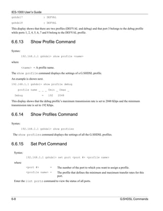
![IES-1000 User’s Guide
Figure 9-1 Default VLAN Settings
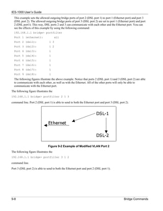
9.6.1 Portfilter Command
Syntax:
192.168.1.1 bridge> portfilter [<source port> all|<dest ports>]
where
<source port> = An incoming bridge port number.
all = All bridge ports are allowed outgoing ports.
<dest ports> = The outgoing bridge ports. Separate by a space if there is more than one
port.
This command sets or displays the port-based VLAN configuration.
An example is shown next.
192.168.1.1 > bridge
192.168.1.1 bridge> portfilter
Port 1 (ethernet): all
Port 2 (dsl1): 1
Port 3 (dsl2): 1
Port 4 (dsl3): 1
Port 5 (dsl4): 1
Port 6 (dsl5): 1
Port 7 (dsl6): 1
Port 8 (dsl7): 1
Port 9 (dsl8): 1
The above shows the current configuration of the port-based VLAN. It is the same as the default settings.
An example with an altered configuration is shown next.
192.168.1.1 > bridge
192.168.1.1 bridge> portfilter 2 1 3
192.168.1.1 bridge> portfilter 3 1 2
Bridge Commands 9-7](https://image.slidesharecdn.com/ies-1000v204usersguide-110321234330-phpapp02/85/Ies-1000-v2-04_users_guide-73-320.jpg)
![IES-1000 User’s Guide
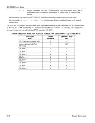
Figure 9-3 Example of Modified VLAN Port 3
The following figure illustrates that port 1 (the Ethernet port) is linked to ports 2 (DSL port 1) and 3 (DSL port 2).
Ports 2 (DSL port1) and 3 (DSL port 2) are also linked to each other. Or, in other words, the following figure is a
result of the following commands:
192.168.1.1 bridge> portfilter 2 1 3
192.168.1.1 bridge> portfilter 3 1 2
Figure 9-4 Example of Modified VLAN Settings
9.7 Tagged Ethernet Frames Commands (Fast Mode)
The network module’s fast mode makes use of the “tag” subset of the IEEE 802.1Q standard to identify the source
port of an Ethernet frame and speed traffic through a service gateway. In this way, the source port of a frame can
be recognized across switches. Fast mode reduces overhead by basing the forwarding decisions on the 802.1Q tag
instead of checking and filtering MAC addresses. Fast mode allows only one port per PVID. Use normal mode
(see 5.5.5) and the 802.1Q VLAN commands (see Chapter 10 ) to configure VLANs or PVIDs with multiple ports.
9.7.1 FPVID Command
Syntax:
192.168.1.1 bridge> fpvid [<port> <vid>]
where
<port> = The port number on the network module. Port 0 is the CPU’s port, port 1 is the
Ethernet port and ports 2-9 are the bridge ports on network module modules.
These are logical ports.
Bridge Commands 9-9](https://image.slidesharecdn.com/ies-1000v204usersguide-110321234330-phpapp02/85/Ies-1000-v2-04_users_guide-75-320.jpg)
![IES-1000 User’s Guide
10.6.1 VLAN Enable Command
The default for the IEEE 802.1Q Tagged VLAN is disable. Enable the IEEE 802.1Q Tagged VLAN by following
the example shown next.
Syntax:
192.168.1.1 vlan1q> vlan enable
10.6.2 VLAN Disable Command
You can disable the IEEE 802.1Q Tagged VLAN by using the VLAN Disable command.
Syntax:
192.168.1.1 vlan1q> vlan disable
This command disables the IEEE 802.1Q Tagged VLAN.
10.6.3 PVID Command
Syntax:
192.168.1.1 vlan1q> pvid [<port #> <vlan id>]
where
<port #> = A bridge port number. Valid parameter range = [1 - 9].
<vlan id> = The VLAN ID. Valid parameter range = [1 - 4094].
10-4 IEEE 802.1QTagged VLAN Commands](https://image.slidesharecdn.com/ies-1000v204usersguide-110321234330-phpapp02/85/Ies-1000-v2-04_users_guide-80-320.jpg)
![IES-1000 User’s Guide
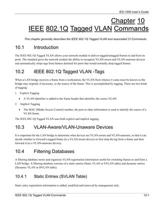
This command sets the VLAN ID to a specific port in the PVID table. To display the PVID table simply enter
this command without parameters, as shown next.
192.168.1.1 vlan1q> pvid
pvid port#
----- -----
1 1
1 2
1 3
1 4
1 5
1 6
1 7
1 8
1 9
192.168.1.1 vlan1q>
Figure 10-1 Example: PVID Command Display
Make sure you set all bonded ports to have the same PVID.
10.6.4 SVLAN CPU Command
Syntax:
192.168.1.1 vlan1q> svlan cpu [<vid>]
where
<vid> = A VLAN ID. Valid parameter range = [1 – 4094].
This command registers your CPU as a port member of the static VLAN with <vid>. To display the CPU
static VLAN identification, simply enter this command without parameters, as shown next.
192.168.1.1 vlan1q> svlan cpu
10.6.5 SVLAN List Command
Syntax:
192.168.1.1 vlan1q> svlan list
IEEE 802.1Q Tagged VLAN Commands 10-5](https://image.slidesharecdn.com/ies-1000v204usersguide-110321234330-phpapp02/85/Ies-1000-v2-04_users_guide-81-320.jpg)
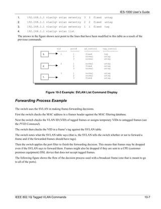
![IES-1000 User’s Guide
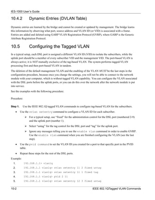
This command displays the static VLAN registration table. The following figure is an example of what is
displayed when you use this command.
vid port# ad_control tag_control
-------- ------- ------------ ------------
1 1 fixed Tag
2 normal UnTag
3 normal UnTag
2 1 normal UnTag
2 fixed UnTag
3 normal UnTag
3 1 normal UnTag
2 normal UnTag
3 fixed UnTag
Figure 10-2 Example: SVLAN List Command Display
For more information about the Svlan List command display, refer to the Svlan Setentry command (shown next).
10.6.6 SVLAN Setentry Command
Syntax:
192.168.1.1 vlan1q> svlan setentry <vid> <port#> <ad_control>
<tag_control>
where
<vid> = A VLAN ID. Valid parameter range = [1 – 4094].
<port#> = A bridge port number.
Valid parameter range = [1 – 9].
<ad_control> = Registrar administration control flag.
Valid parameters = [fixed, forbidden, normal].
Select fixed to register a <port #> to the static VLAN table with
<vid>.
Select normal to confirm registration of the <port #> to the static
VLAN table with <vid>.
Select forbidden to block a <port #> from joining the static VLAN table
with <vid>.
<tag_control> = The tag control flag. Valid parameters = [tag, untag].
Select tag to add tags to outgoing frames.
Select untag if you do not want to tag outgoing frames.
This command adds or modifies an entry into the static VLAN table. Display your configuration by using the
Svlan List command. An example of a configuration is shown next.
Modify a Static VLAN Table Example
The following is an example of how to modify a static VLAN table.
10-6 IEEE 802.1QTagged VLAN Commands](https://image.slidesharecdn.com/ies-1000v204usersguide-110321234330-phpapp02/85/Ies-1000-v2-04_users_guide-82-320.jpg)
![IES-1000 User’s Guide
10.6.7 SVLAN Getentry Command
Syntax:
192.168.1.1 vlan1q> svlan getentry <vid>
where
<vid> = A VLAN ID. Valid parameter range = [1 – 4094].
This command displays an entry with a specified VLAN ID in the static VLAN table.
Display a Static VLAN Table Entry Example
The following figure is an example display of the following command.
192.168.1.1 vlan1q> svlan getentry 2
vid port# ad_control tag_control
-------- ------- ------------ ------------
2 1 normal UnTag
2 fixed UnTag
3 normal UnTag
Figure 10-5 Example: Svlan Getentry 2 Command Display
10.6.8 SVLAN Delentry Command
Syntax:
192.168.1.1 vlan mgr> svlan delentry <vid>
where
<vid> = A VLAN ID. Valid parameter range = [1 – 4094].
This command deletes an entry with a specified VLAN ID in the static VLAN table
Delete a Static VLAN Entry Example
The following example will delete entry 2 in the static VLAN table.
192.168.1.1 vlan mgr> svlan delentry 2
10.6.9 DVLAN List Command
Syntax:
192.168.1.1 vlan1q> dvlan list
This command displays the dynamic VLAN registration table. The following figure is an example of what is
displayed when you use this command.
IEEE 802.1Q Tagged VLAN Commands 10-9](https://image.slidesharecdn.com/ies-1000v204usersguide-110321234330-phpapp02/85/Ies-1000-v2-04_users_guide-85-320.jpg)
![IES-1000 User’s Guide
vid 01 02 03 04 05 06 07 08 09
---- ---- ---- ---- ---- ---- ---- ---- ---- ----
2 || >> || || >> >> || || >>
3 >> >> || || || >> >> >> ||
4 >> || || >> >> || || >> >>
5 || >> || || >> >> || || >>
6 >> >> || || || >> >> >> ||
7 || >> || >> >> || || >> >>
8 >> || || >> || >> >> >> >>
9 || >> || || || >> || >> >>
Figure 10-6 Example: DVLAN List Command Display
In the figure above, “||” denotes “filter” and “>>” denotes “forward”.
10.6.10 DVLAN Getentry Command
Syntax:
192.168.1.1 vlan1q> dvlan getentry <vid>
where
<vid> = A VLAN ID. Valid parameter range = [1 – 4094].
This command displays an entry with a specified VLAN ID in dynamic GVRP table.
Display a Dynamic VLAN Table Entry Example
The following figure is an example display of the following command.
192.168.1.1 vlan1q> dvlan getentry 2
vid 01 02 03 04 05 06 07 08 09
---- ---- ---- ---- ---- ---- ---- ---- ---- ----
2 || >> || || >> >> || || >>
Figure 10-7 Example: DVLAN Getentry 2 Command Display
In the figure above, “||” denotes “filter” and “>>” denotes “forward”.
10.6.11 VLAN List Command
Syntax:
192.168.1.1 vlan1q> vlan list
This command displays the entire VLAN table. The display refreshes periodically. Press [ENTER] and then
enter the stop command to stop the display from refreshing. The following figure is an example what is
displayed when you use this command.
10-10 IEEE 802.1QTagged VLAN Commands](https://image.slidesharecdn.com/ies-1000v204usersguide-110321234330-phpapp02/85/Ies-1000-v2-04_users_guide-86-320.jpg)


![IES-1000 User’s Guide
Chapter 11
IEEE 802.1p Priority Commands
This chapter explains IEEE 802.1p Priority CI Commands.
11.1 Introduction
IEEE 802.1p Priority CI Commands assign priority levels to individual ports. IEEE 802.1p defines up to eight
priorities (0-7) by inserting a tag into a MAC-layer frame that contains bits to define priority of service.
11.2 IEEE 802.1p Priority Commands
Bridge port 1 stands for the Ethernet port, bridge port 2 stands for DSL port 1, bridge port 3
stands for DSL port 2, and so on.
11.2.1 Priority Port Command
Syntax:
192.168.1.1 vlan1q> priority port <port #> <priority>
where
<port #> = A bridge port number. Valid parameter range = [1 - 9].
<priority> = The default priority for the specified port. Valid parameter range = [0 - 7],
where 0 is the lowest priority and 7 is the highest priority.
This command sets the default priority that is assigned to untagged frames from a specified ingress port.
To display the default port priority table, simply use the Priority Port command without parameters, as
shown next.
192.168.1.1 vlan1q> priority port
IEEE 802.1p Priority Commands 11-1](https://image.slidesharecdn.com/ies-1000v204usersguide-110321234330-phpapp02/85/Ies-1000-v2-04_users_guide-89-320.jpg)
![IES-1000 User’s Guide
11.2.2 Regen Port Command
Syntax:
192.168.1.1 vlan1q> regen port [<port #> <user priority> <regened
priority>]
where
<port #> = A bridge port number. Valid parameter range = [1 – 9].
<user priority> = The user priority for a frame received on this port. Valid
parameter range = [0 – 7 or *], where 0 is the lowest priority, 7 is
the highest priority and * means all user priorities.
<regened priority> = The regenerated user priority the incoming user priority is
mapped to for <port #>. Valid parameter range = [0 - 7],
where 0 is the lowest priority and 7 is the highest priority.
This command changes the priority of a tagged frame from a specified ingress port from the original user
priority to the regened priority.
To display the regeneration table, simply use the Regen Port command without parameters, as shown next.
192.168.1.1 vlan1q> regen port
11-2 IEEE 802.1p Priority Commands](https://image.slidesharecdn.com/ies-1000v204usersguide-110321234330-phpapp02/85/Ies-1000-v2-04_users_guide-90-320.jpg)
![IES-1000 User’s Guide
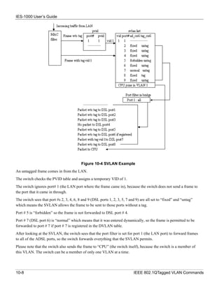
For example, if you want the IES-1000 to have 172.21.100.1 as the IP address, 255.255.255.0 for the subnet mask
and 172.21.100.254 for the default gateway, you may use the following command sequence:
192.168.1.1> ip
192.168.1.1 ip> enable ether 172.21.100.1
192.168.1.1 ip> subnet delete ether.home
192.168.1.1 ip> subnet add ether.home ether 172.21.100.0 ff:ff:ff:00
192.168.1.1 ip> route delete default
192.168.1.1 ip> route add default 0.0.0.0 172.21.100.254 00:00:00:00
192.168.1.1 ip> config save
Figure 12-1 Setting IP Address and Default Gateway
The IES-1000 leaves the factory with a default IP address of 192.168.1.1 and a subnet mask of 255.255.255.0, or
FF.FF.FF.0 in hexadecimal notation, and the default gateway set at 192.168.1.254. Make sure that you configure
the IP parameters correctly before you connect an IES-1000 to the network, otherwise, you may interrupt services
already running.
12.2 General IP Commands
The following is a list of general IP commands that help with the management of the IP parameters.
12.2.1 Config Command
Syntax:
192.168.1.1 ip> config [save]
This command shows the IP configuration. The save option saves the configuration to the nonvolatile memory.
12.2.2 Version Command
Syntax:
192.168.1.1 ip> version
This command shows the IP version and MAC address of the network module.
12-2 IP Commands](https://image.slidesharecdn.com/ies-1000v204usersguide-110321234330-phpapp02/85/Ies-1000-v2-04_users_guide-92-320.jpg)
![IES-1000 User’s Guide
12.2.3 Ping Command
Syntax:
192.168.1.1 ip> ping <host> [<ttl> [<size>]]
where
<host> = The IP address of the target.
<ttl> = Time to Live (optional). This parameter limits the number of hops (routers) that the
echo request can travel before it reaches the target.
<size> = The parameter specifies the size of the payload, that is, not counting the headers, of
the echo request. The default size is 32 octets.
This is an IP facility to check for network functionality by sending an echo request to another IP host and
waiting for the reply.
12.2.4 Statistics Command
Syntax:
192.168.1.1 ip> stats <sub cmd>
This command shows the statistics for the traffic of the type specified by the sub-command. Statistics are
available for the following traffic types: ARP, ICMP, IP, raw, TCP and UDP.
12.2.5 Subnet Add Command
Syntax:
192.168.1.1 ip> subnet add <net name> <i/f name> a.b.c.d am:bm:cm:dm
where
<net name> = Define the name of the subnet for identification purposes.
<i/f name> = The name of an interface (“ether” for this device).
a.b.c.d = The subnet’s IP address.
am:bm:cm:dm = The subnet’s subnet mask.
This command defines a subnet. Type “subnet” without any parameters to view a list of the configured subnets.
12.2.6 Subnet Delete Command
Syntax:
192.168.1.1 ip> subnet delete <net name>
where
<net name> = The name of the subnet.
This command removes a subnet.
IP Commands 12-3](https://image.slidesharecdn.com/ies-1000v204usersguide-110321234330-phpapp02/85/Ies-1000-v2-04_users_guide-93-320.jpg)
![IES-1000 User’s Guide
12.2.7 Subnet Flush Command
Syntax:
192.168.1.1 ip> subnet flush
This command removes all of the subnets.
12.2.8 Route Add Command
Syntax:
192.168.1.1 ip> route add <dom name> a.b.c.d <relay> [am:bm:cm:dm [<cost>
]]
where
<dom name> = The name of the static route.
a.b.c.d = The destination IP address of packets that this static route is to route.
<relay> = The IP address of the gateway that you want to send the packets through.
am:bm:cm:dm = The destination subnet mask of packets that this static route is to route.
<cost> = The metric (hop count) of this static route.
This command defines a new, static IP forwarding route or edits an existing one. Type “route” without any
parameters to view a list of the configured static routes.
Use 0’s for the destination IP address and subnet mask to configure a default static route for the device. The
device uses the default static route to forward packets for which it cannot find another route. The following is
the syntax for configuring a static route.
192.168.1.1 ip> route add <dom name> 0.0.0.0 <relay> 0:0:0:0
12.2.9 Route Delete Command
Syntax:
192.168.1.1 ip> route delete <dom name>
where
<dom name> = The name of the static route.
This command removes a static, IP forwarding route.
12.2.10 Route Flush Command
Syntax:
192.168.1.1 ip> route flush
This command removes all of the static IP forwarding routes.
12-4 IP Commands](https://image.slidesharecdn.com/ies-1000v204usersguide-110321234330-phpapp02/85/Ies-1000-v2-04_users_guide-94-320.jpg)
![IES-1000 User’s Guide
12.2.11 Enable Command
Your telnet session disconnects when you change the Ethernet port’s IP address. Initiate a
telnet session to the new IP address in order to reconnect.
Syntax:
192.168.1.1 ip> enable [<i/f> [mtu <size>] [<IPaddr>]]
where
<i/f> = The name of an interface (“ether” for this device).
[mtu <size>] = Maximum Transmit Unit. The maximum packet size that this interface is to
send.
<IPaddr> = The IP address of the device’s interface.
This command sets the Ethernet port’s IP address and the largest packet size that this interface sends.
IP Commands 12-5](https://image.slidesharecdn.com/ies-1000v204usersguide-110321234330-phpapp02/85/Ies-1000-v2-04_users_guide-95-320.jpg)

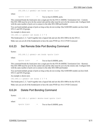
![IES-1000 User’s Guide
♦ Trap
Used by the agent to inform the manager of some events.
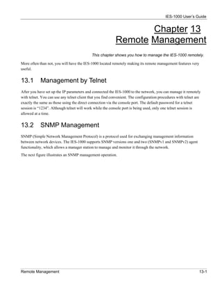
13.2.1 Supported MIBs
The network module supports MIB II that is defined in RFC 1213 and RFC 1215 as well as transparent bridge
MIBs defined in RFC 1493. The network module can also respond with specific data from the ZyXEL private
MIB (ZYXEL-MIB).
13.3 SNMP Access Configuration
To control access to the agent in the network module, use the access commands in the SNMP subsystem. Note
that “community” is SNMP’s terminology for password. After configuring the SNMP access parameters, save the
configuration to the nonvolatile memory with the config save command. The default write community string
is “1234”, and the default read community string is “public”.
13.3.1 SNMP Access Read/Write Command
Syntax:
access <read | write> <community> [<IP addr>]
where
<read | write> = Specifies read-only/read-write permission.
<community> = The password needed to access the SNMP agent on the network module.
[<IP addr>] = The optional IP address of the allowed SNMP manager.
This command allows read-only or read-write access. If the IP address is specified, access is allowed for the
manager station with that address only.
13.3.2 SNMP Access Delete Command
Syntax:
access delete <community> [<IP addr>]
This command revokes SNMP access by the specified community (password). If the IP address is specified,
access is denied for that manager station only.
13.3.3 SNMP Access Flush Command
Syntax:
access flush
Remote Management 13-3](https://image.slidesharecdn.com/ies-1000v204usersguide-110321234330-phpapp02/85/Ies-1000-v2-04_users_guide-99-320.jpg)

![IES-1000 User’s Guide
Chapter 14
Configuration Backup/Restore
This chapter describes the process for backing up your user settings (configuration) from the network
module onto your computer and how to restore them to the network module.
The network modules use FTP for configuration backup/restore through their built-in FTP servers. You can use
any FTP client (for example, ftp.exe in Windows) to backup/restore the network module’s configuration.
14.1 Configuration Files of the Network Module
The network module uses configuration files to store the user’s settings, so they can be applied the next time the
network module is booted. The network module has the following two configuration files:
init = The system configuration file for the network module.
password = The configuration file for the console, Telnet and FTP password.
14.2 Configuration Backup
You can backup all or some configuration files from the network module to your computer. Backup the system
configuration by following the example shown next.
Connect to the network module with your favorite FTP client. The command for the network module is generally
C:> ftp <network module IP address>
at the computer command prompt.
Enter the User name (just press [ENTER]).
User: <ENTER>
Enter the management password (1234 by default).
Password: 1234
230 Logged in
Get the configuration files from the network module
ftp> get init
Quit FTP.
ftp> quit
14.3 Configuration Restore
You can restore configuration files from your computer to the network module. Restore the system configuration
by following the example shown next.
Configuration Backup/Restore 14-1](https://image.slidesharecdn.com/ies-1000v204usersguide-110321234330-phpapp02/85/Ies-1000-v2-04_users_guide-103-320.jpg)
![IES-1000 User’s Guide
Do not turn off the network module during the restore process, as it may corrupt the firmware
and make your network module unusable.
Connect to the network module with your favorite FTP client. The command for the network module is generally
C:> ftp < network module IP address>
at the computer command prompt.
Enter the User name (just press [ENTER]).
User: <ENTER>
Enter the management password (1234 by default).
Password: 1234
230 Logged in
Transfer the configuration files to the network module
ftp> put init
Quit FTP.
ftp> quit
Wait for the update to finish. The network module will restart automatically.
14-2 Configuration Backup/Restore](https://image.slidesharecdn.com/ies-1000v204usersguide-110321234330-phpapp02/85/Ies-1000-v2-04_users_guide-104-320.jpg)
![IES-1000 User’s Guide
Do not turn off the network module during the updating process, as it may corrupt the firmware
and make your network module unusable.
1. Connect to the network module with your favorite FTP client.
The command for the network module is generally: ftp < network module IP address> at the
computer command prompt.
2. Enter the user name (just press [ENTER]). For example,
User: <ENTER>
3. Enter the management password (1234 by default). For example,
Password: 1234
230 Logged in
4. Transfer the firmware file to the network module. For example,
ftp> put 201AS0b1.img image
where
201AS0b1.img = The firmware file that you want to upload.
image = The internal firmware name in the network module.
5. Quit FTP. For example,
ftp> quit
Wait for the update to finish. The network module will restart automatically.
Do not turn off the IES-1000 during the updating process, as it may corrupt the firmware and
make your unit unusable.
15.2 BOOTP/TFTP Firmware Recovery of the Network
Module
The network modules use BOOTP/TFTP for firmware recovery through their built-in BOOTP/TFTP client when
the network modules are restarted. To recover the firmware, first download it from the ZyXEL web site and store
it on your computer. You can use any BOOTP/TFTP server (for example, BootpTftp.exe) to update the network
module’s firmware. The update procedure for BootpTftp.exe is as follows:
Do not turn off the IES-1000 during the updating process, as it may corrupt the firmware and
make your unit unusable.
1. Connect your network module’s LAN port to a computer’s LAN port directly using a crossover
Ethernet cable, or connect both to an Ethernet hub/switch using straight-through cables.
2. Connect your network module’s console port to a computer’s serial port with a console cable.
3. Run any terminal emulation program, for example, Windows’ built-in HyperTerminal, with the
following parameters:
VT100 terminal emulation
9600 bps
No parity, 8 data bits, 1 stop bit
No flow control
15-2 Firmware Upload and Recovery](https://image.slidesharecdn.com/ies-1000v204usersguide-110321234330-phpapp02/85/Ies-1000-v2-04_users_guide-106-320.jpg)


(1) This document is the user's guide for the IES-1000 Integrated Ethernet Switch version 2.04 from July 2002 by ZyXEL Communications Corporation. (2) It includes information on features, specifications, applications, installation, configuration and operation of the switch. (3) The guide also provides regulatory compliance statements, warranty information and customer support contact details.


