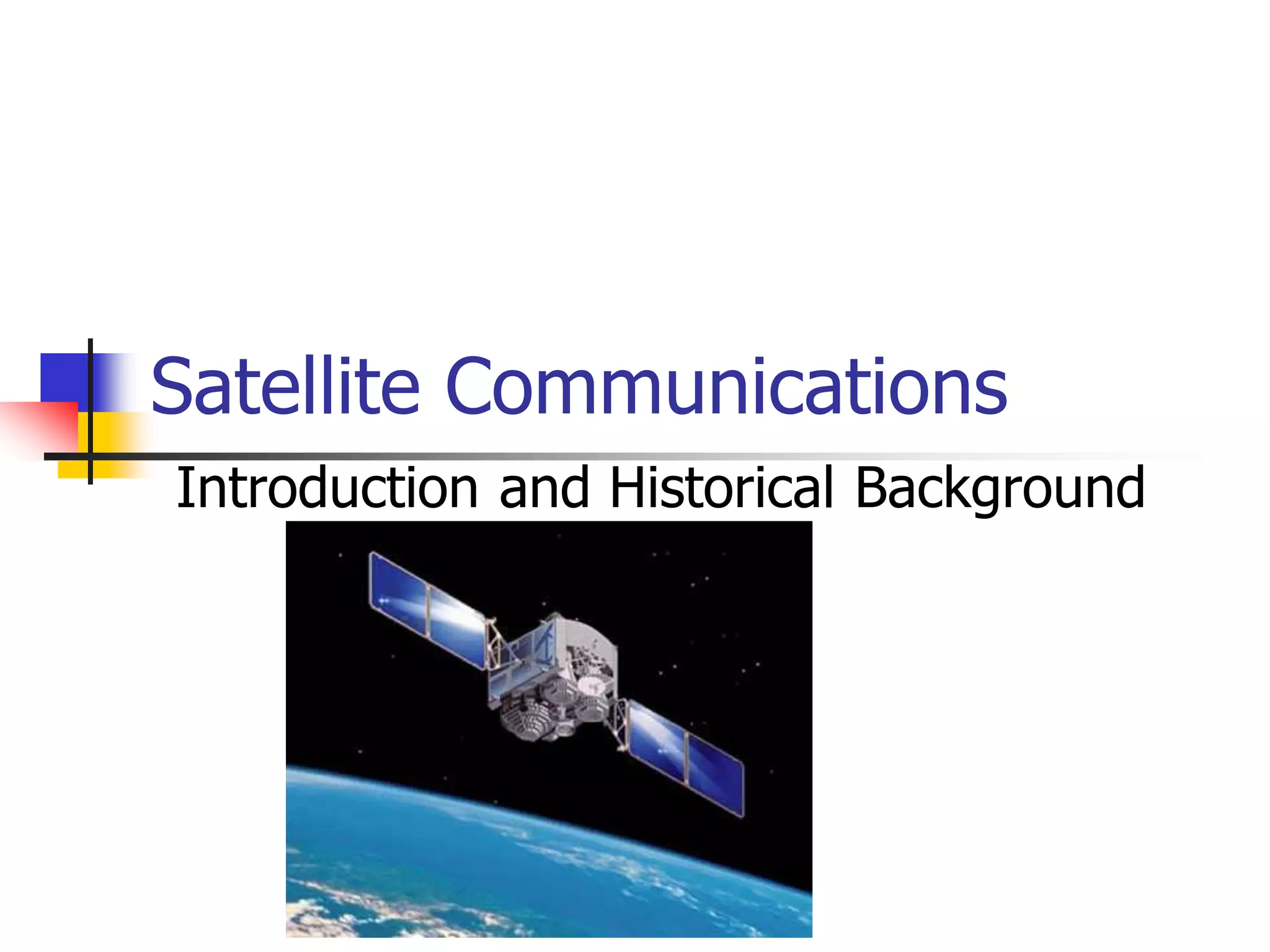
Satellite communications systems allow signals to be transmitted via satellites orbiting Earth rather than via land-based communications infrastructure. The document discusses the history and types of communication satellites, including:
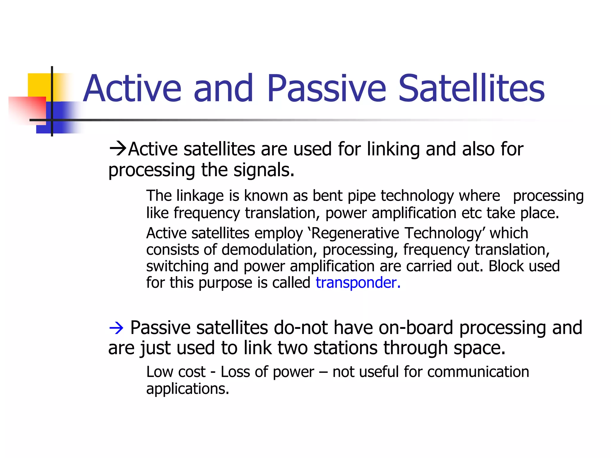
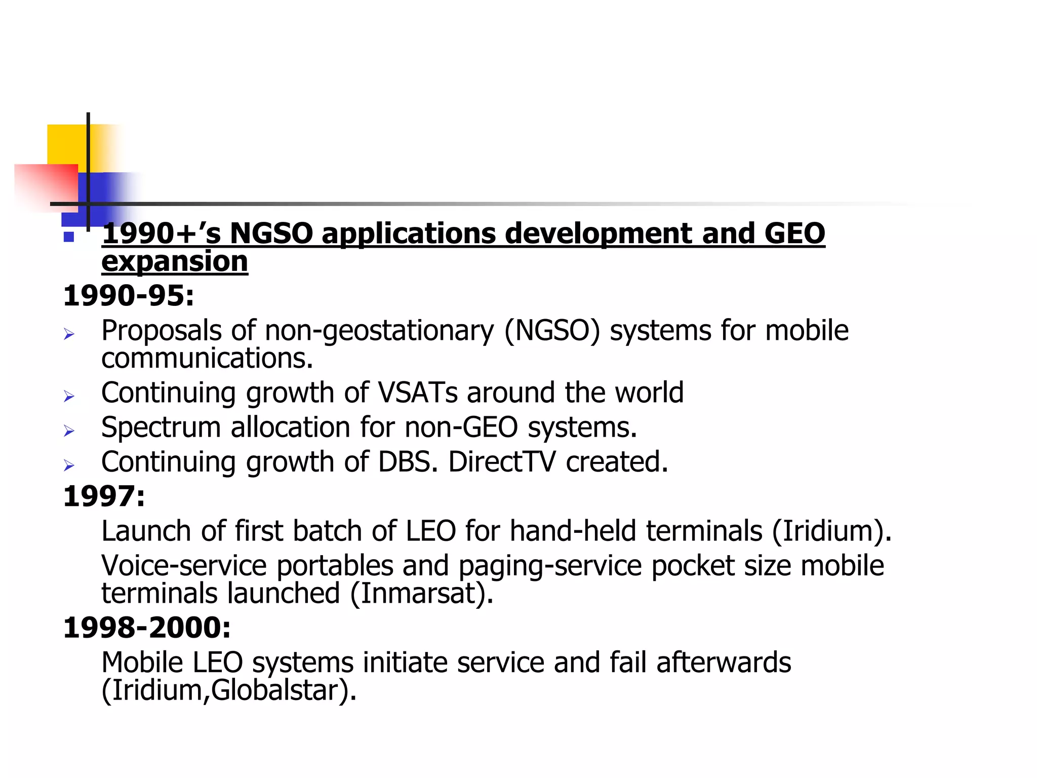
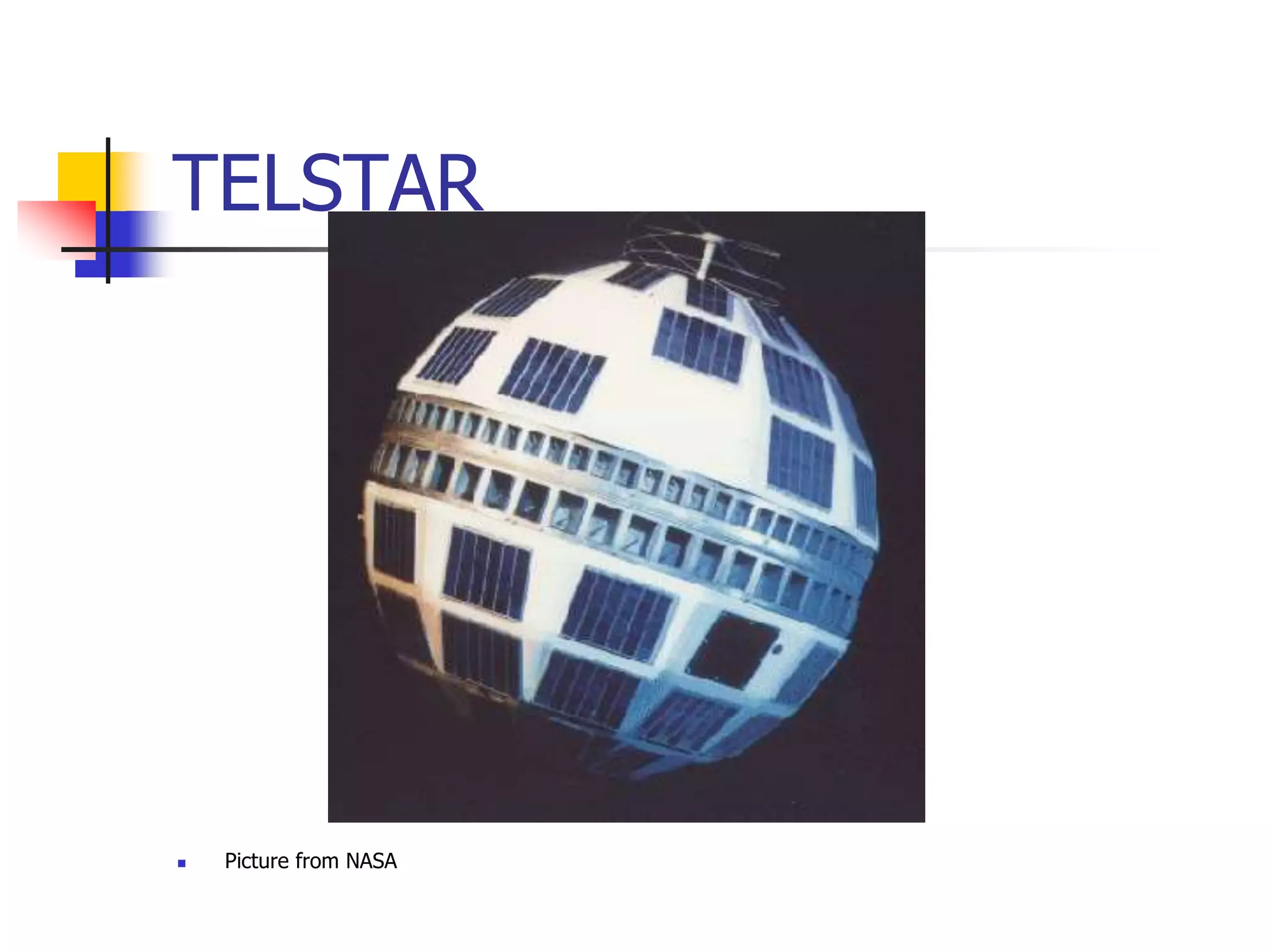
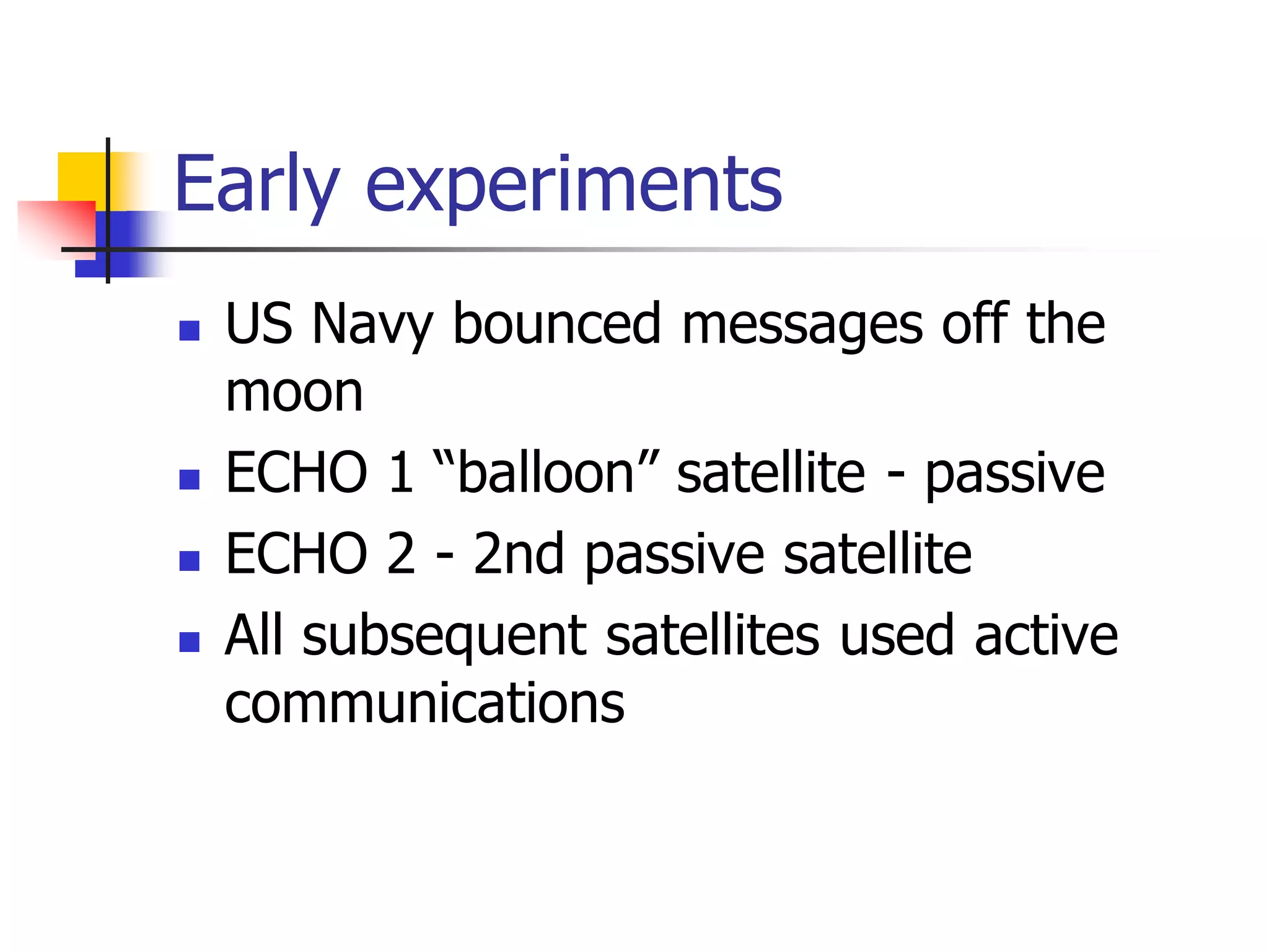
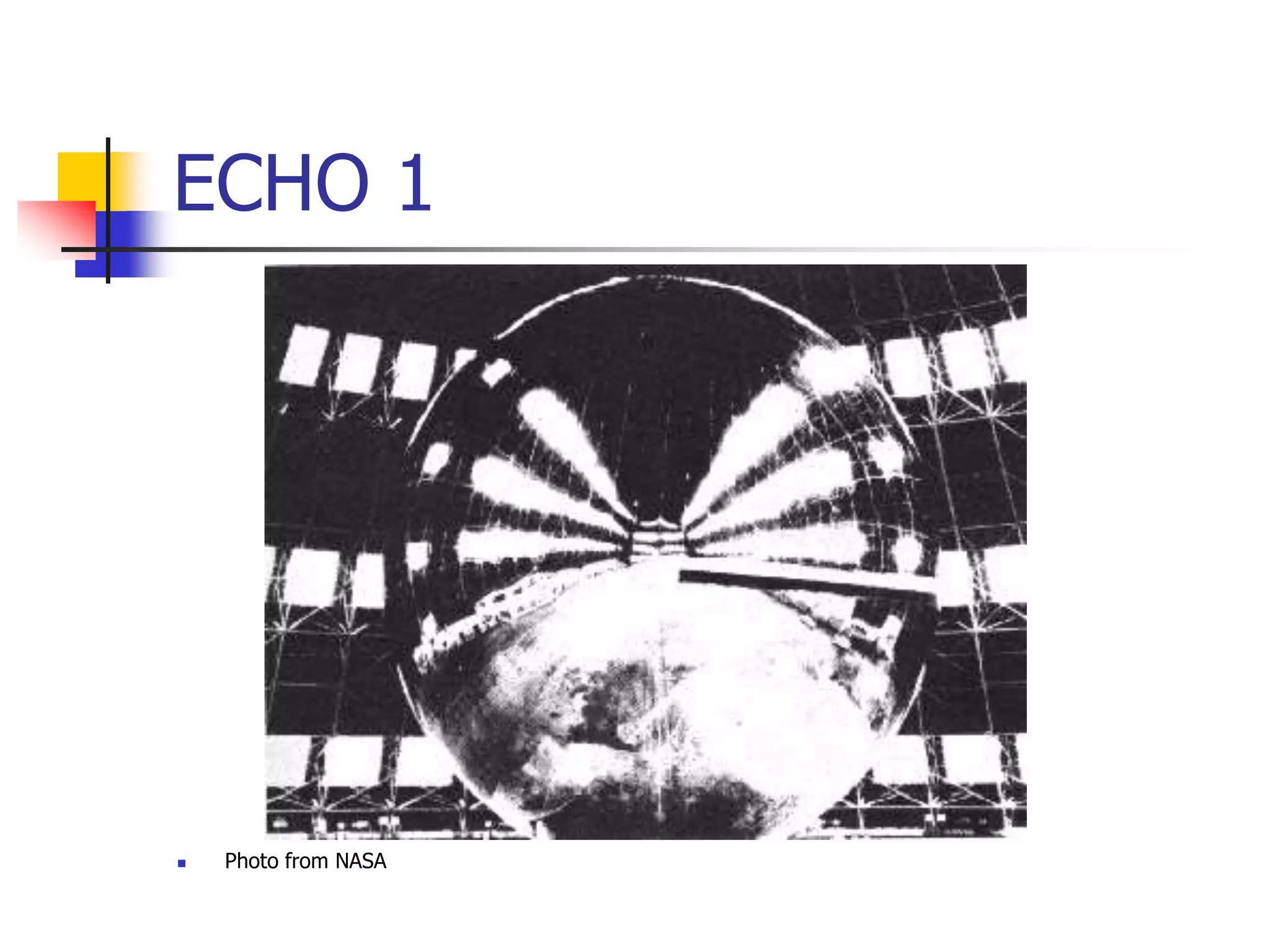
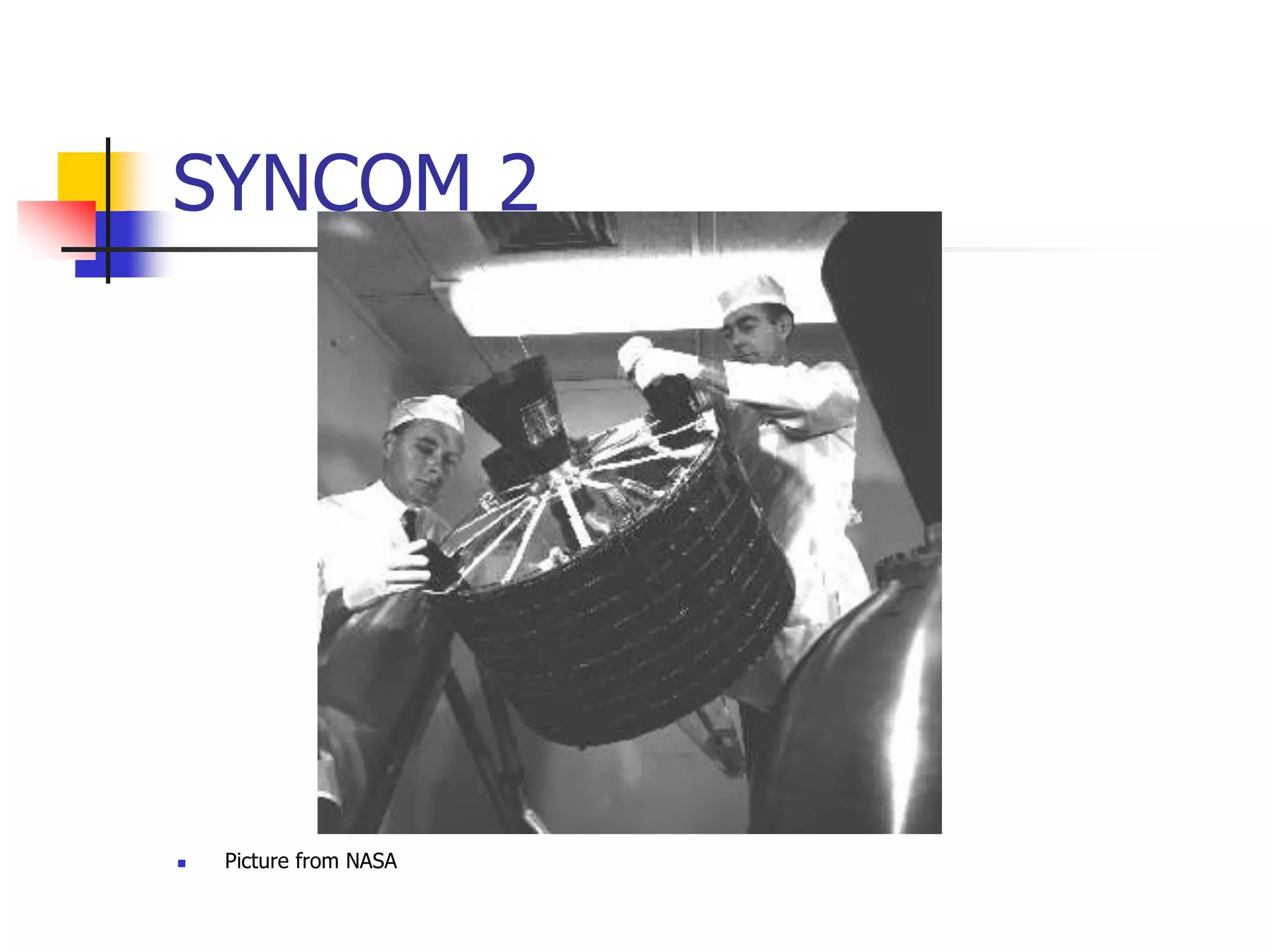
- Early experiments in the 1950s bounced signals off the moon, while the first passive communication satellites (Echo 1 and 2) were balloons. Telstar and Syncom 2 were early active communication satellites.
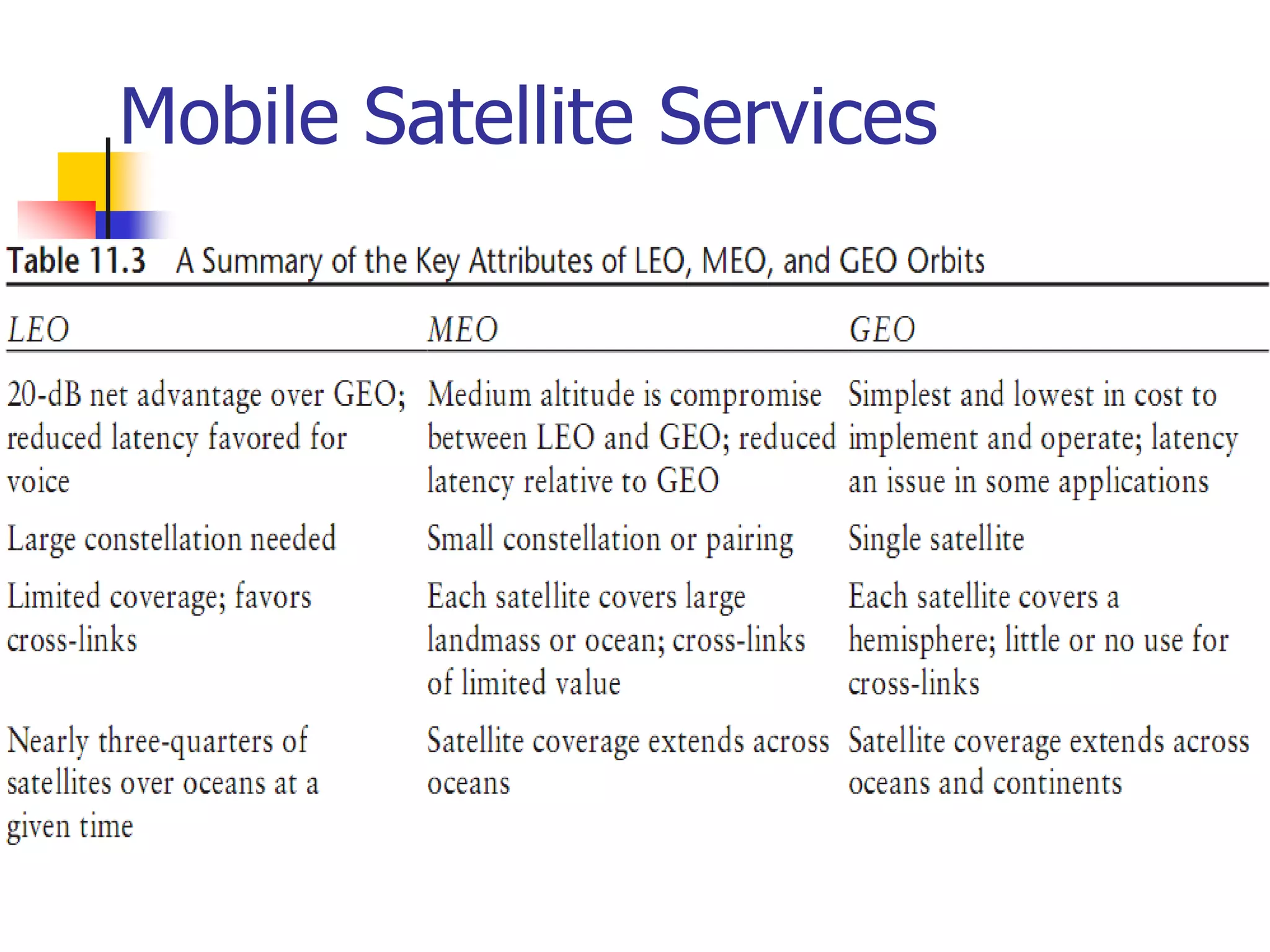
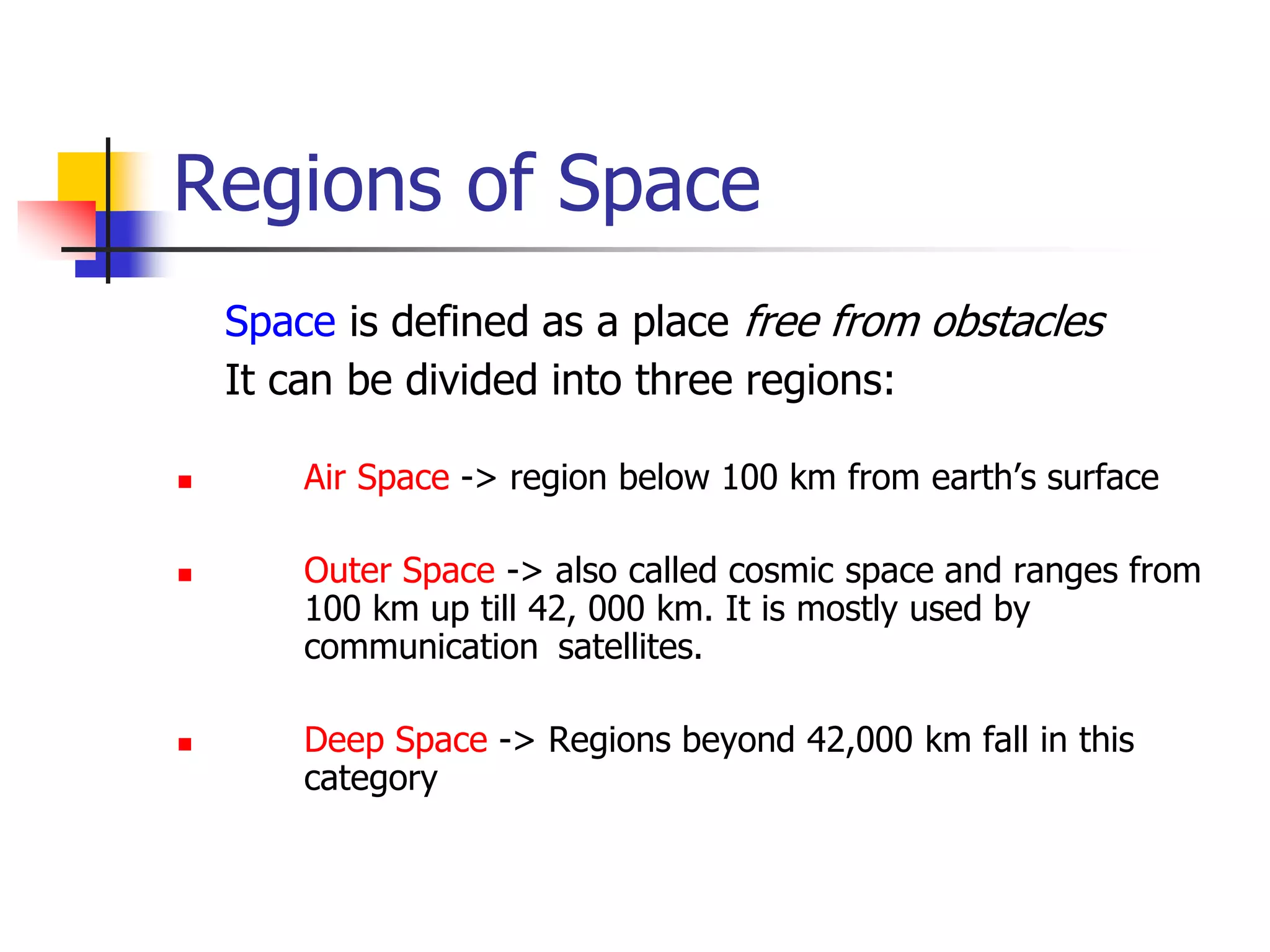
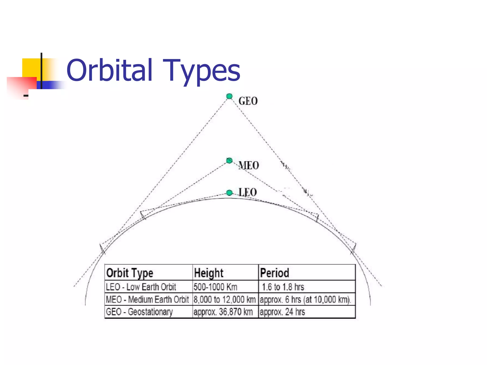
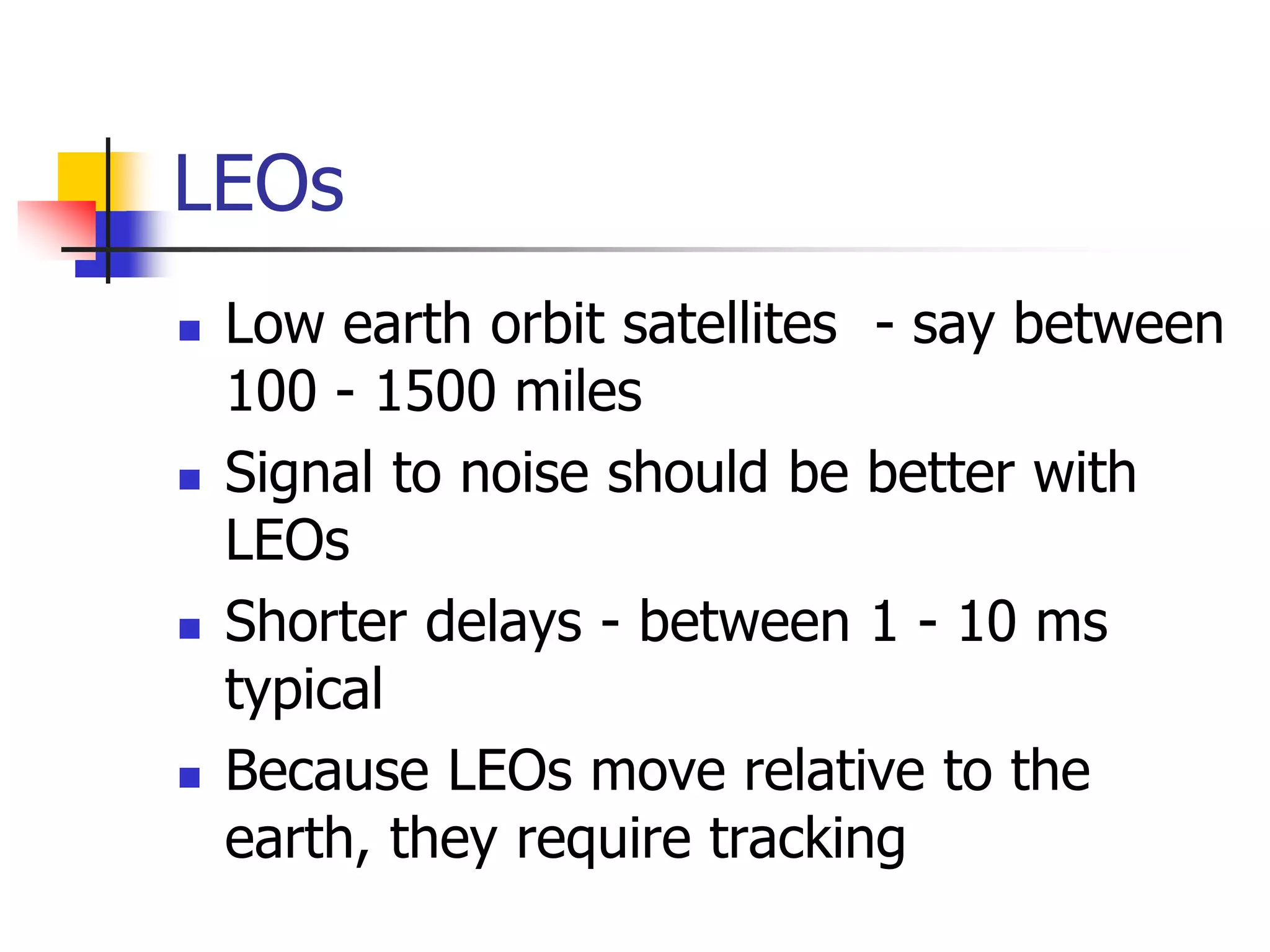
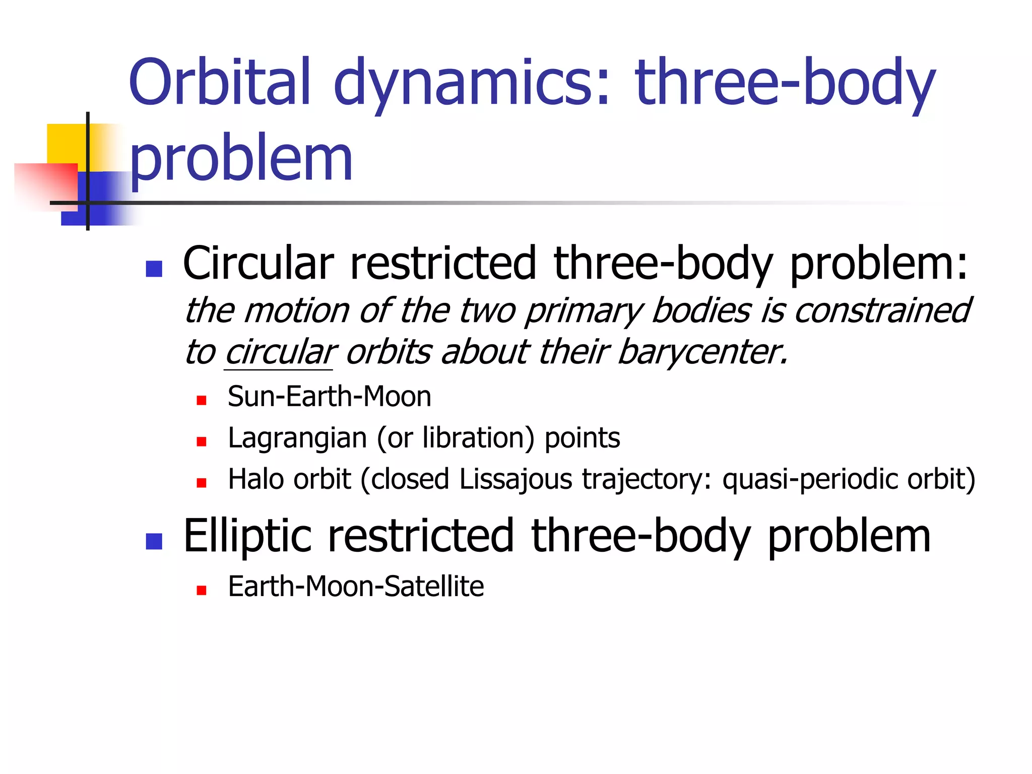
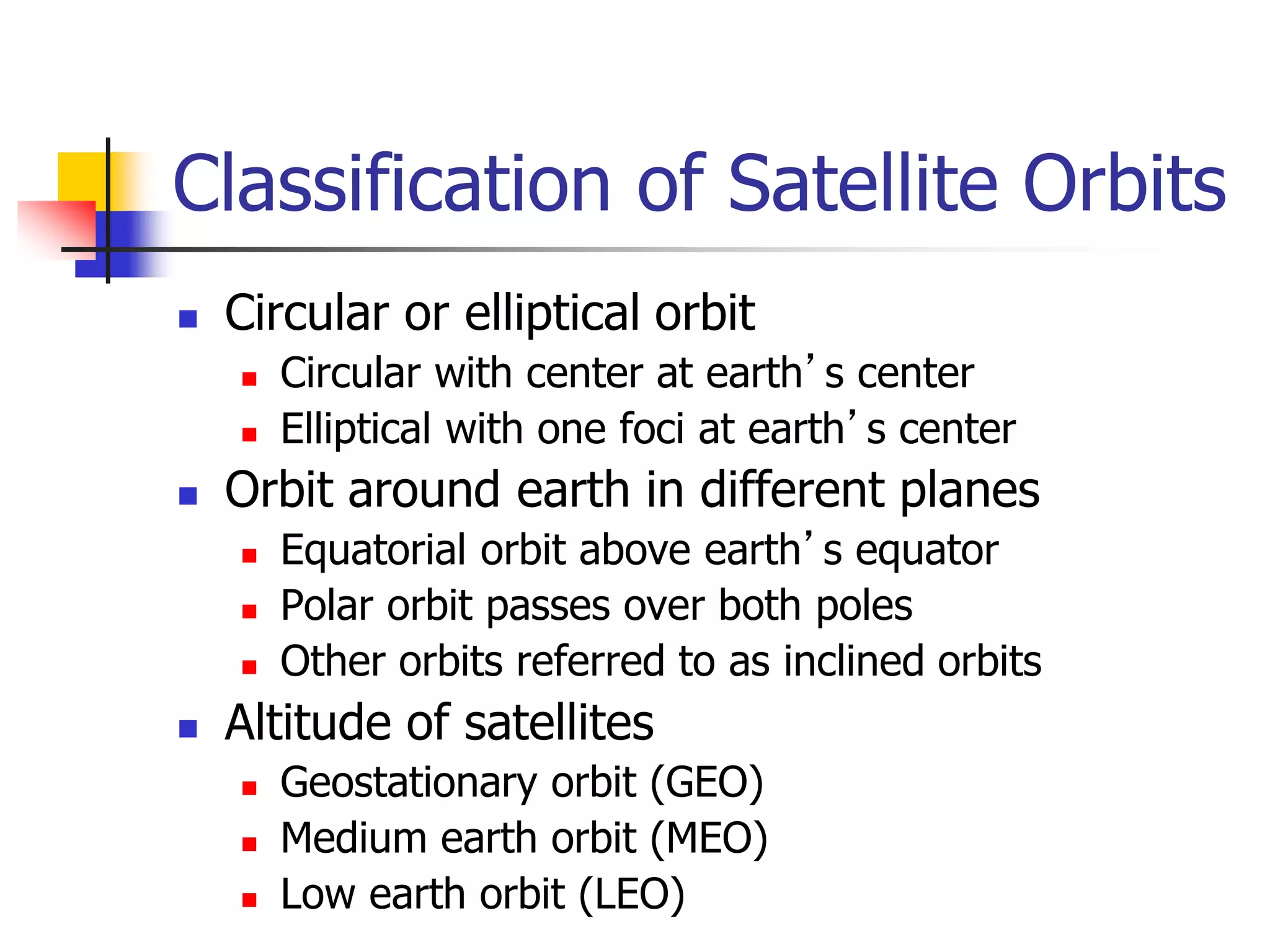
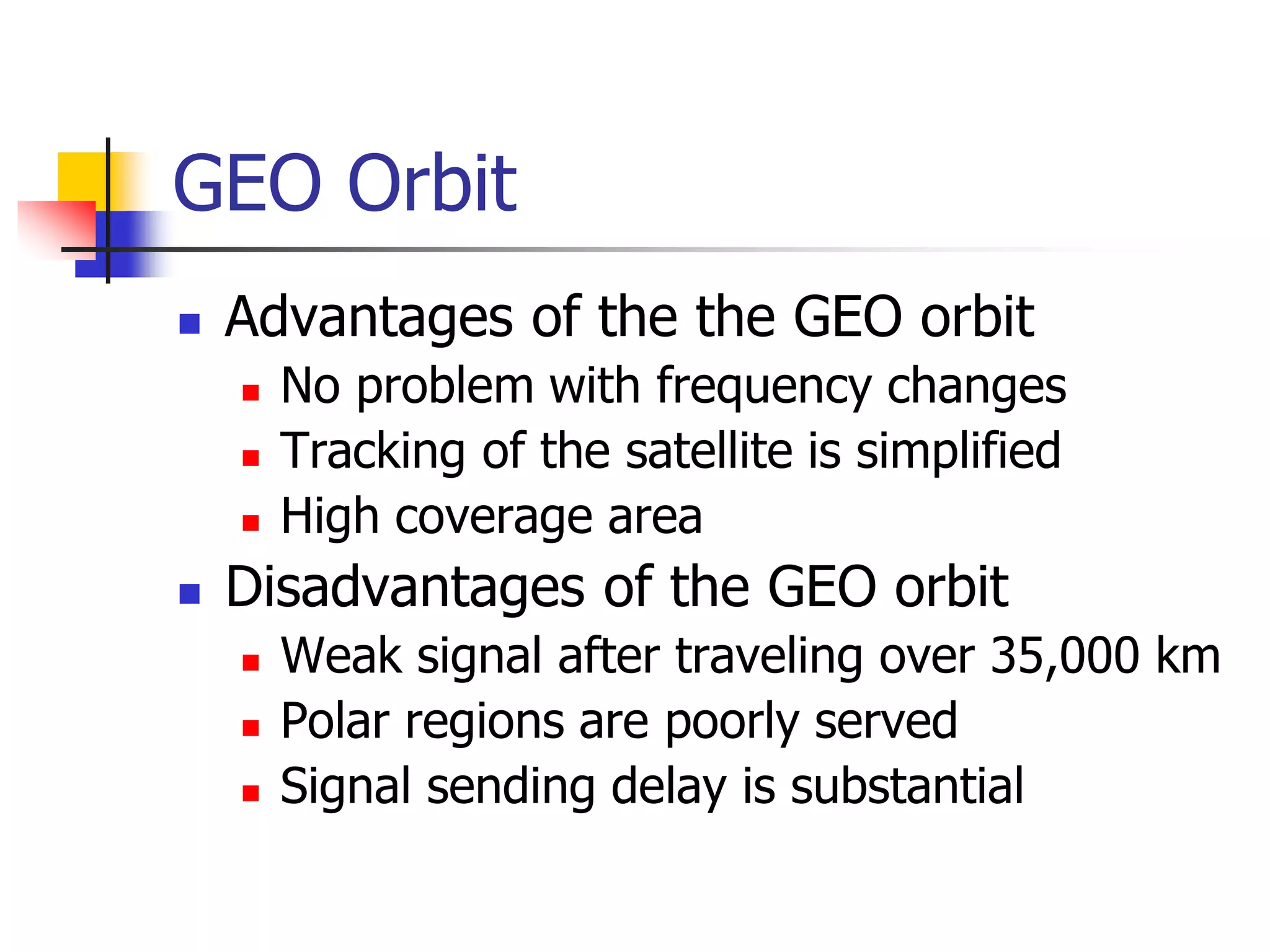
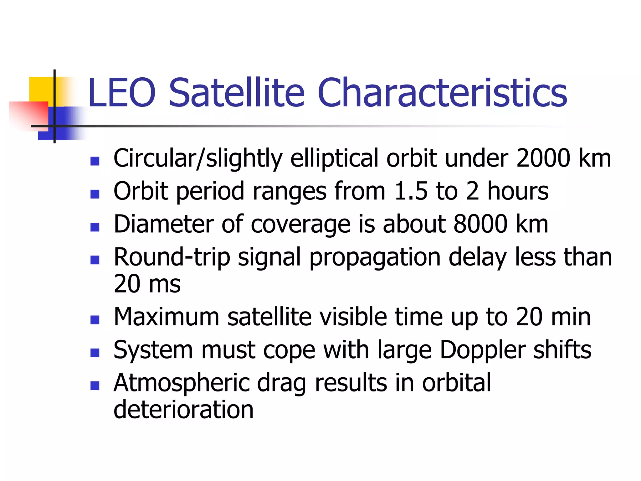
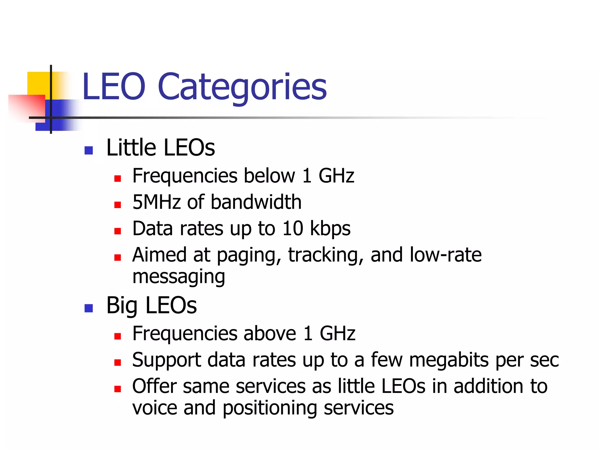
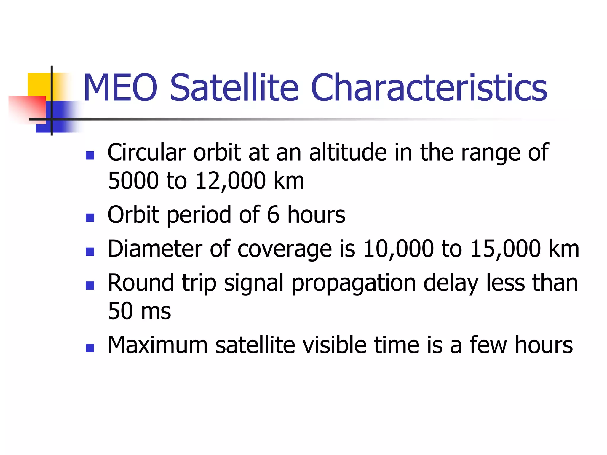
- Satellites can be in low Earth orbit (LEO), medium Earth orbit (MEO), or geostationary Earth orbit (GEO). GEOs orbit at an altitude of about 35,000 km, allowing them to appear stationary from Earth.
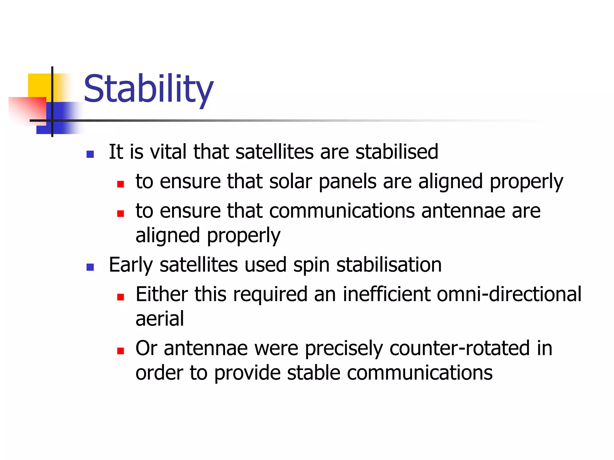
- Challenges for satellite design include maintaining precise orbital positioning,


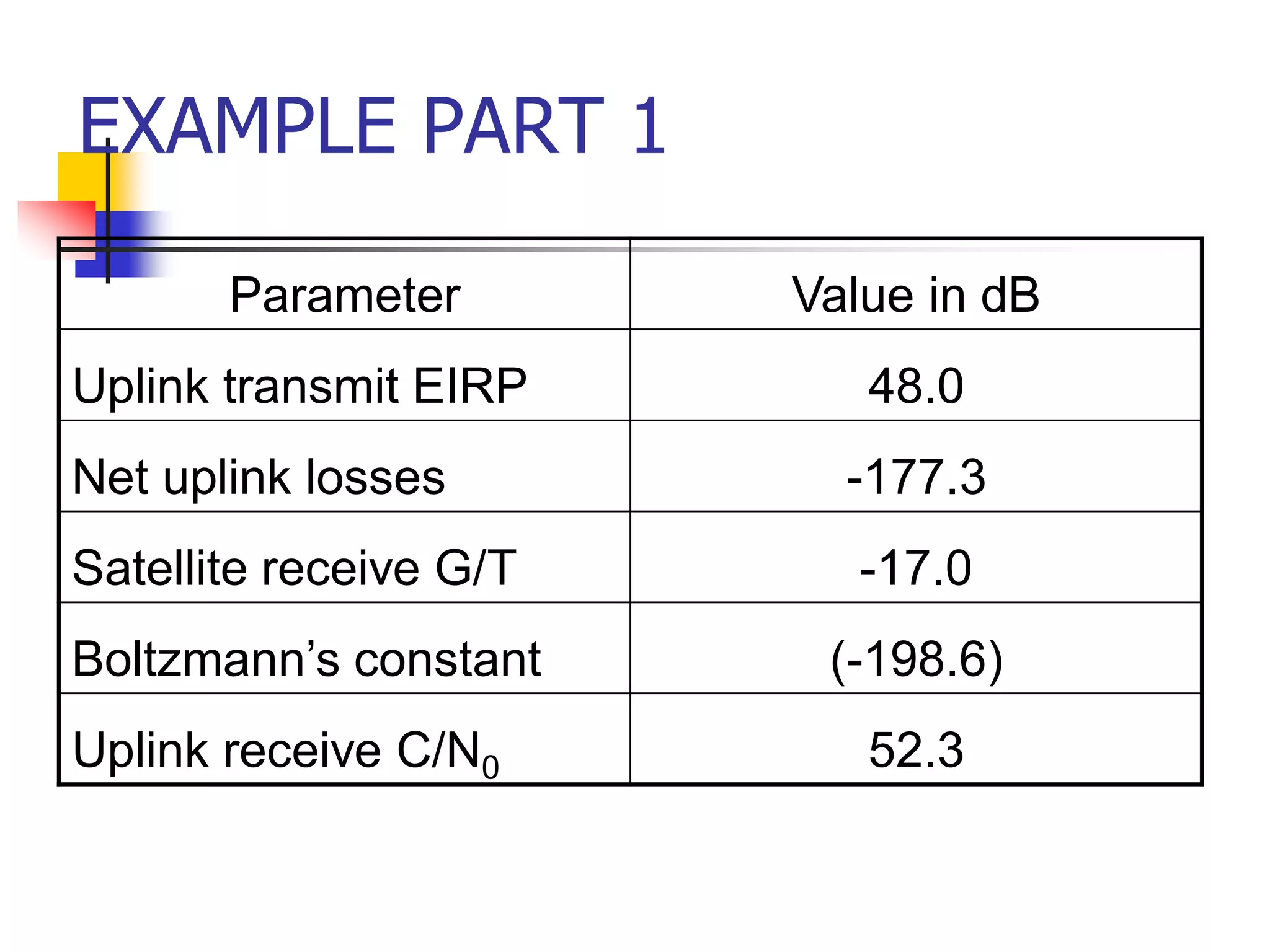
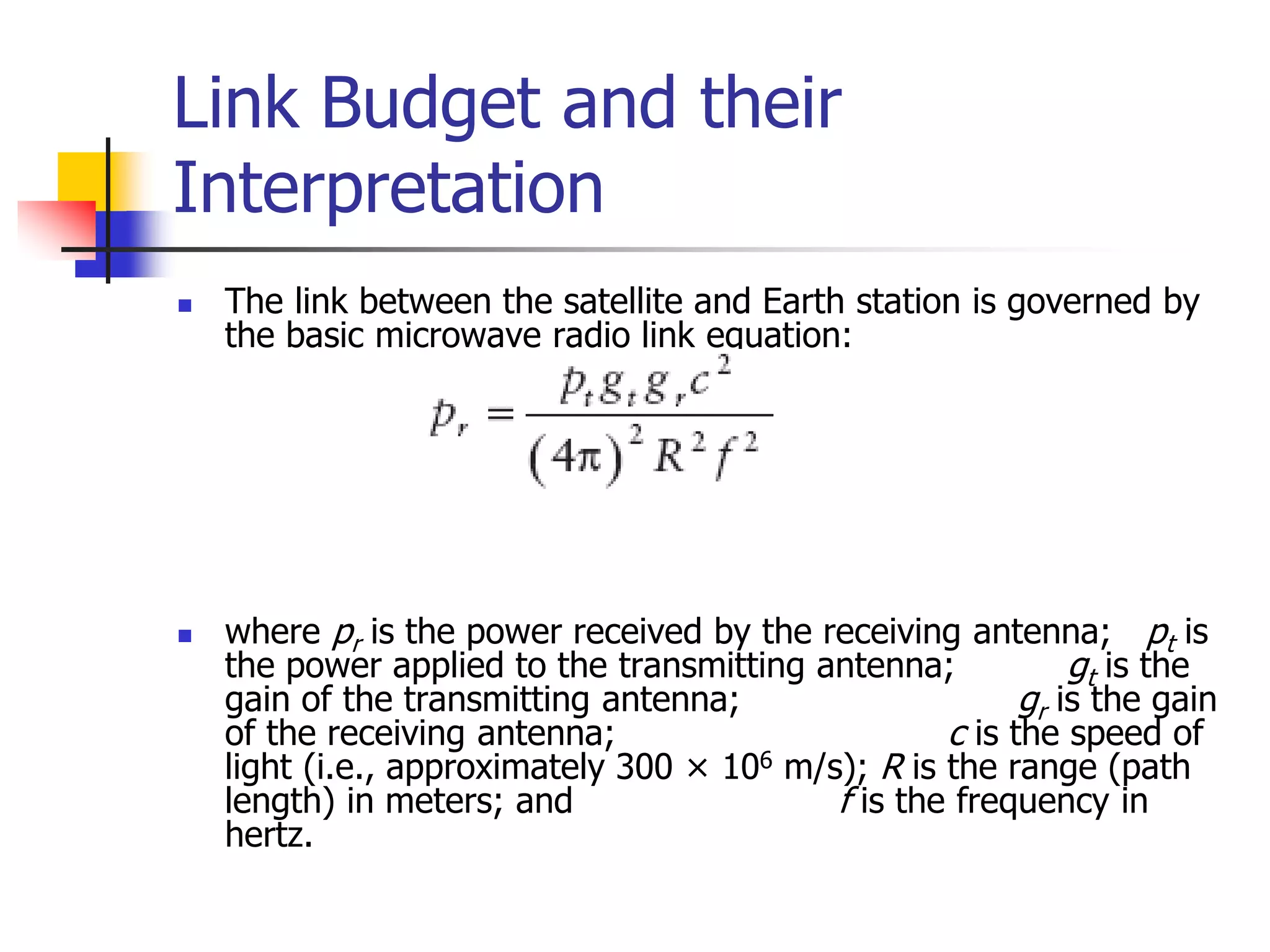
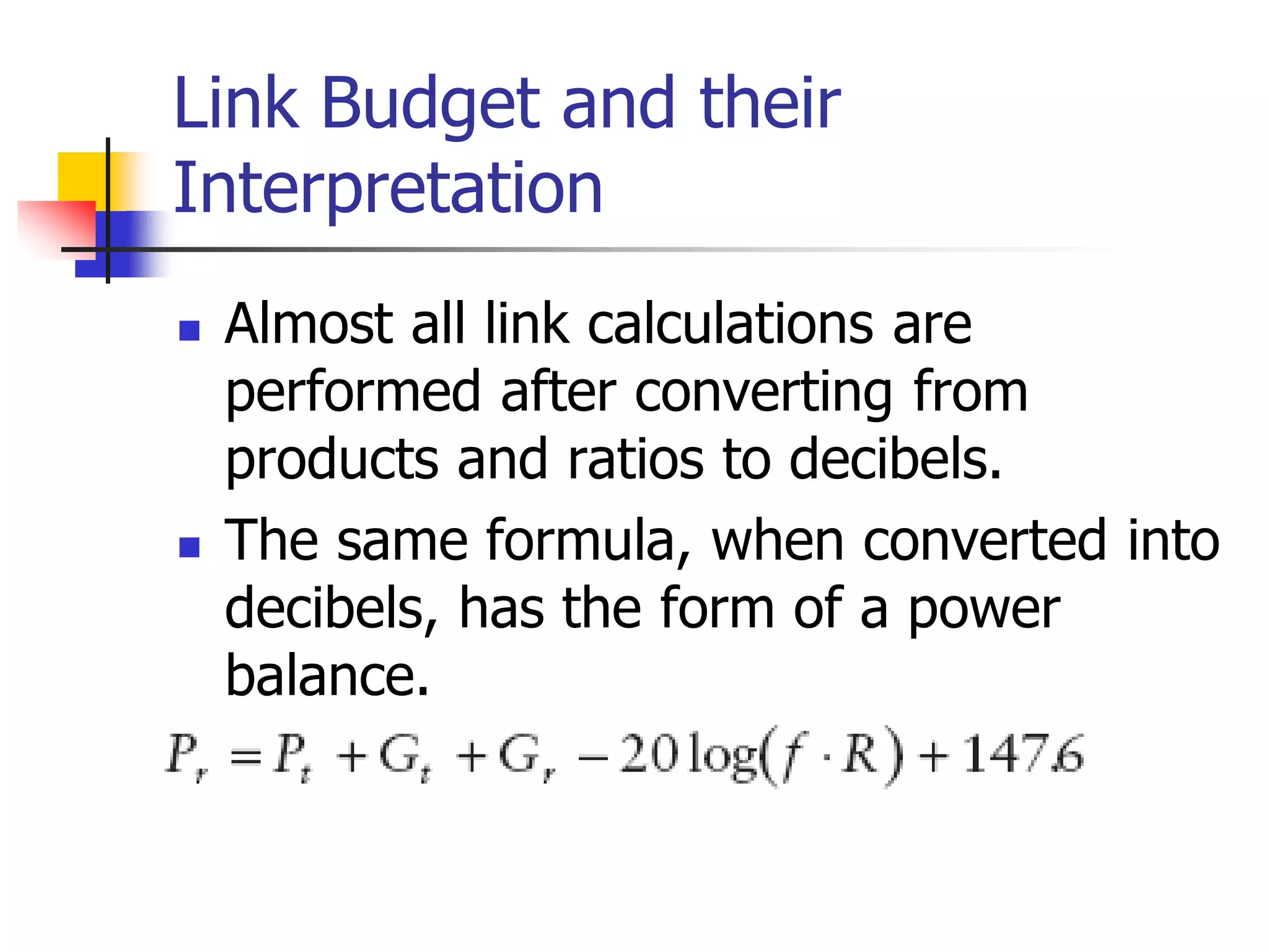
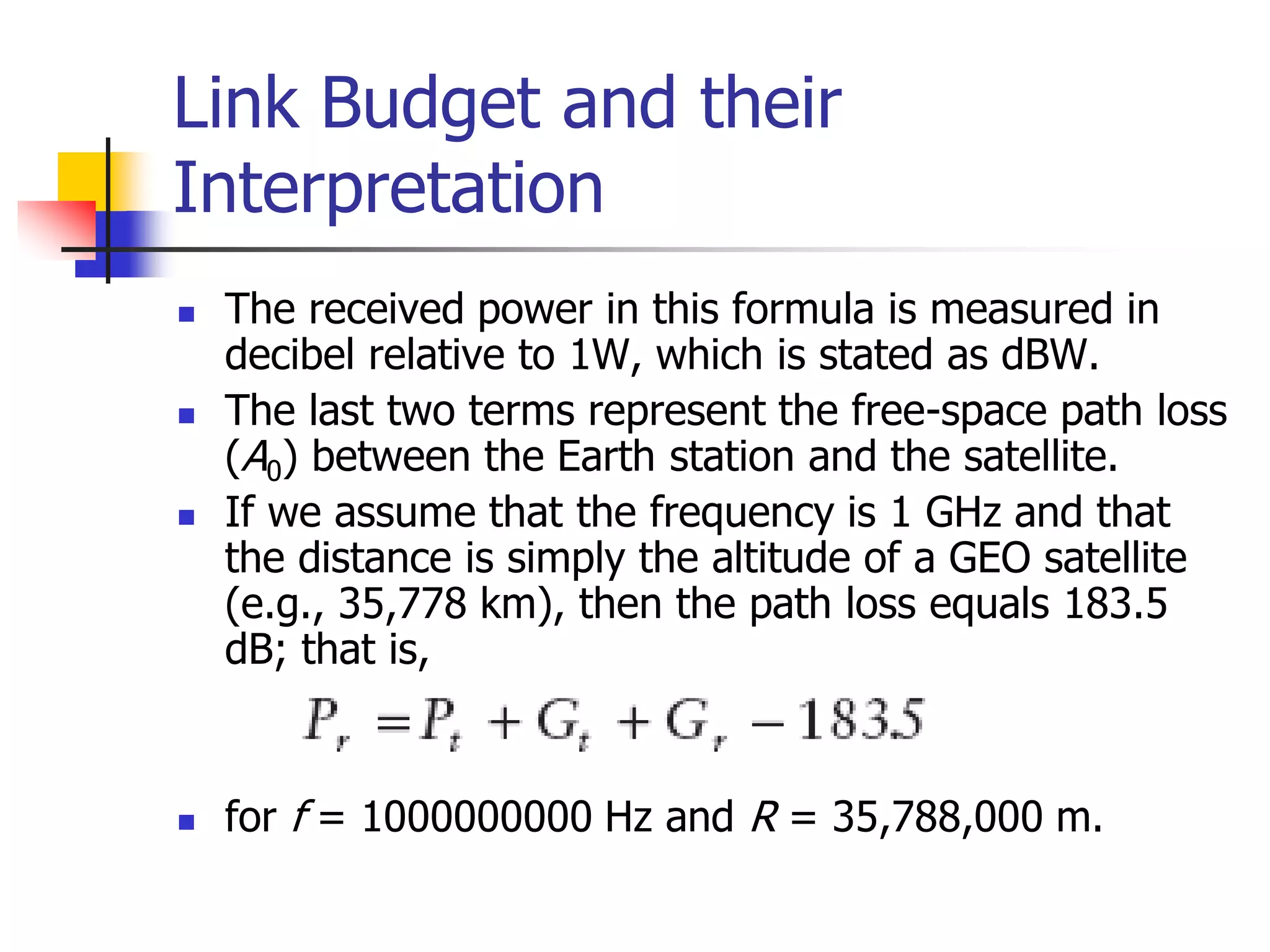
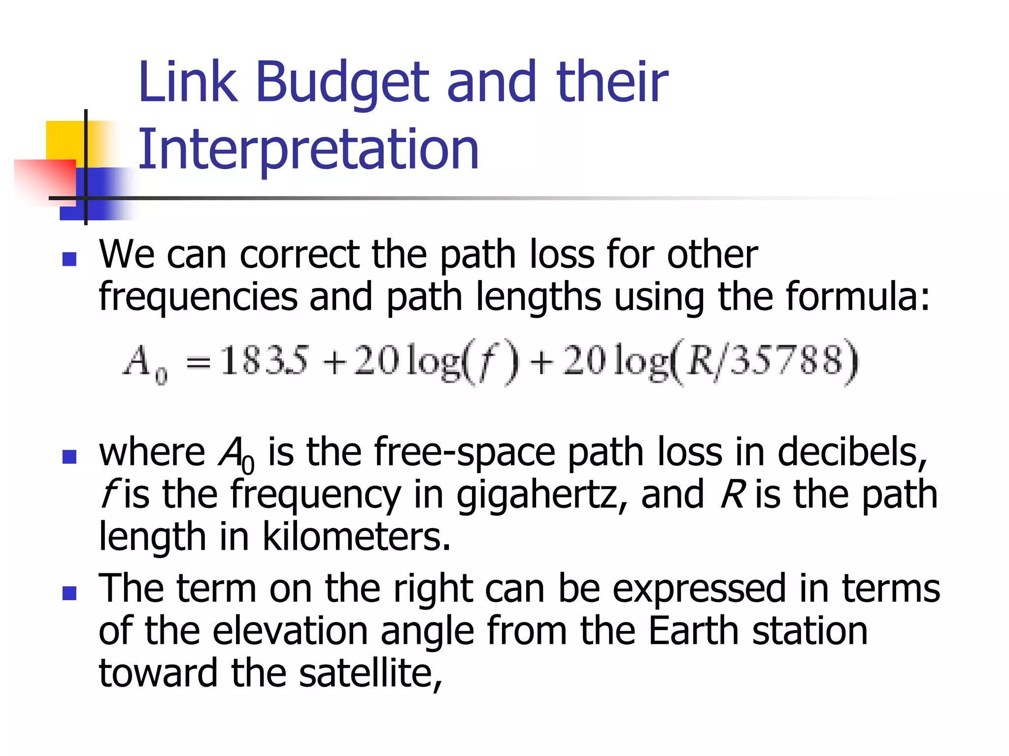
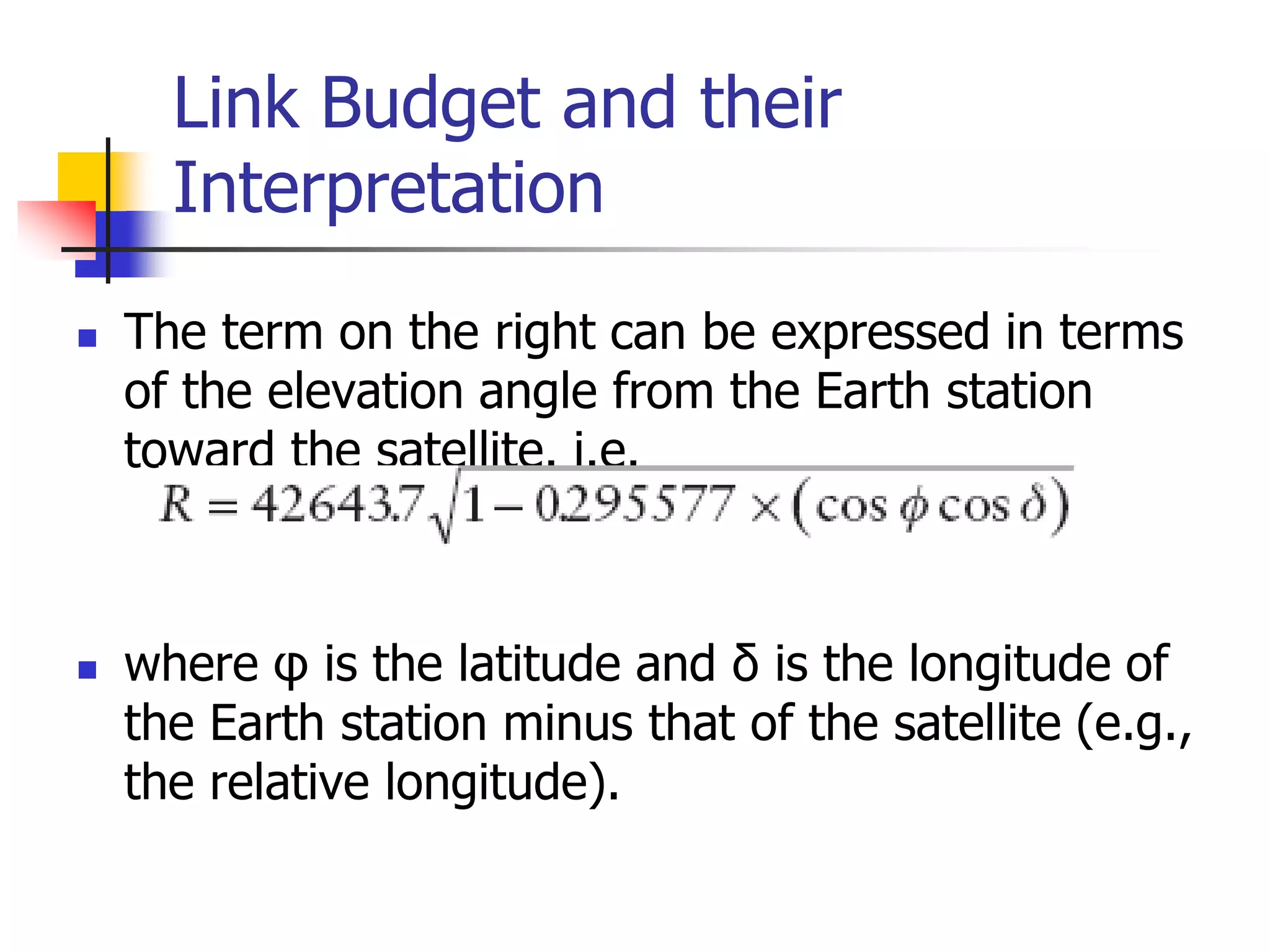
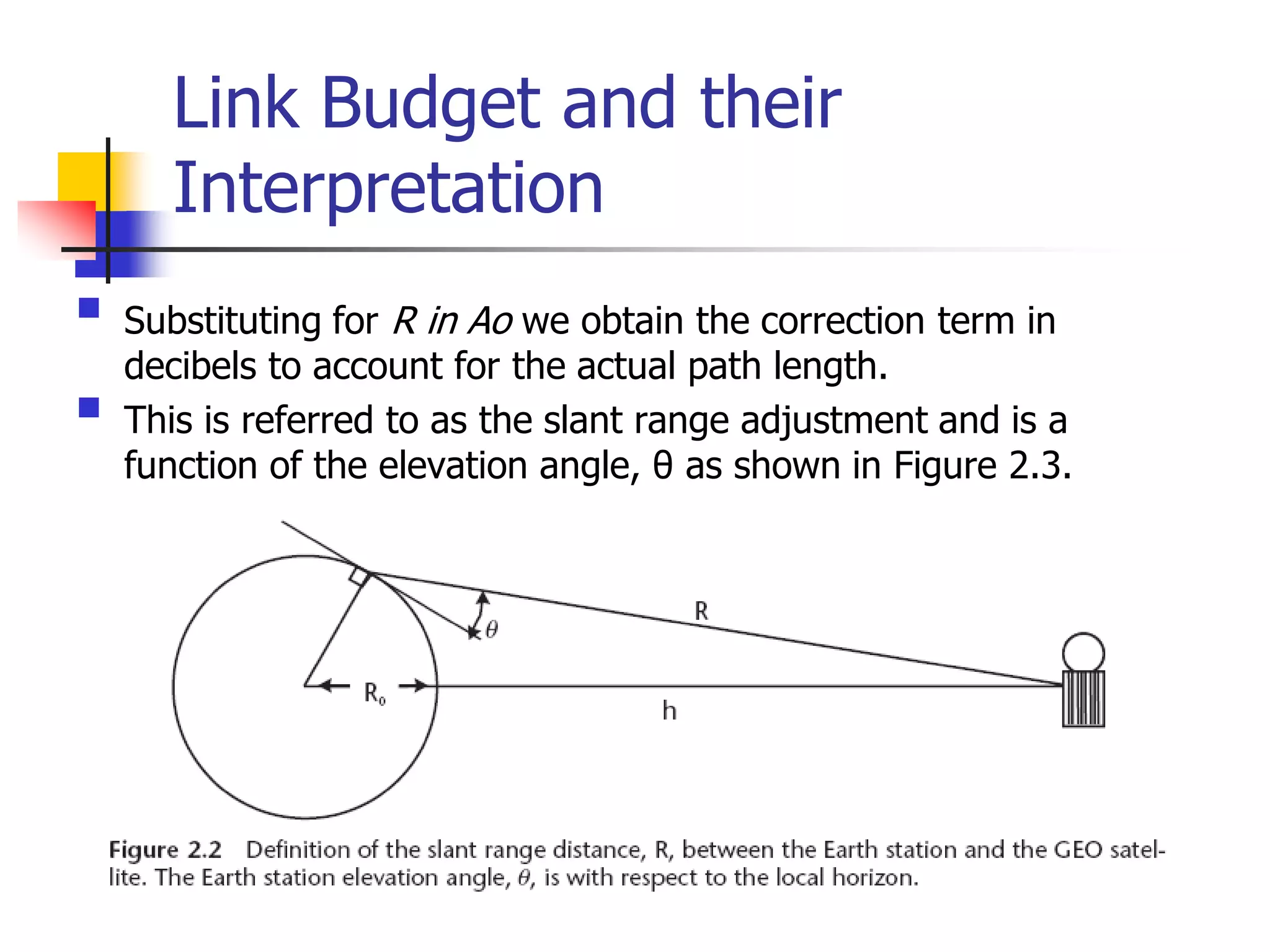
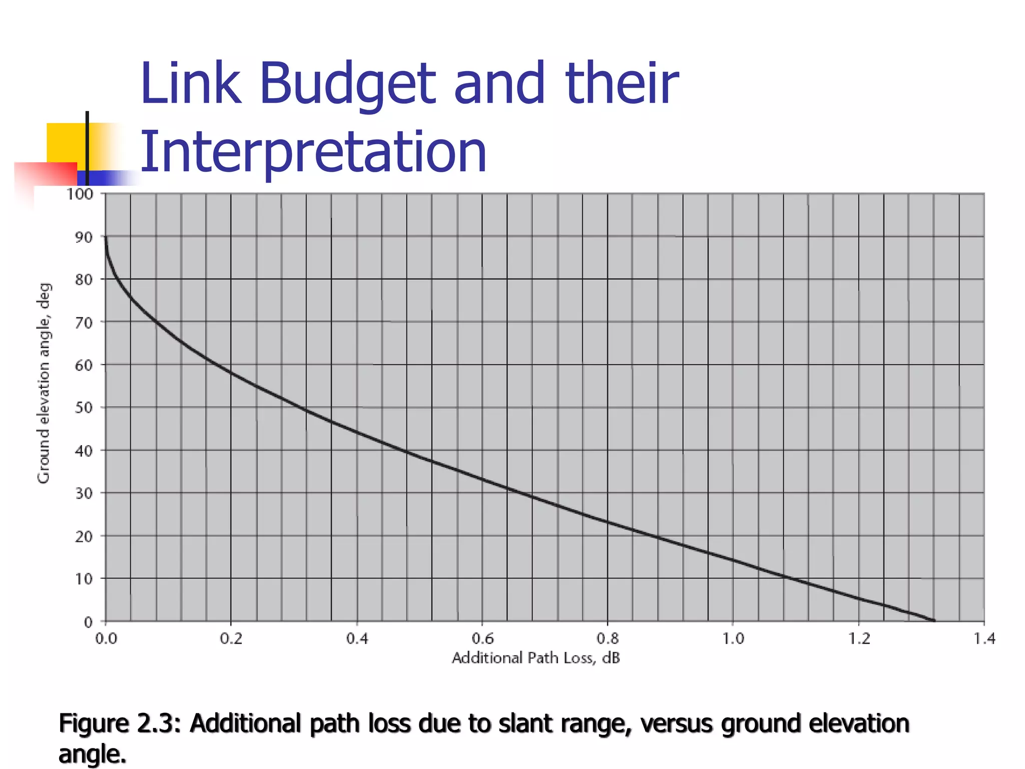
![Link Budget and their
Interpretation
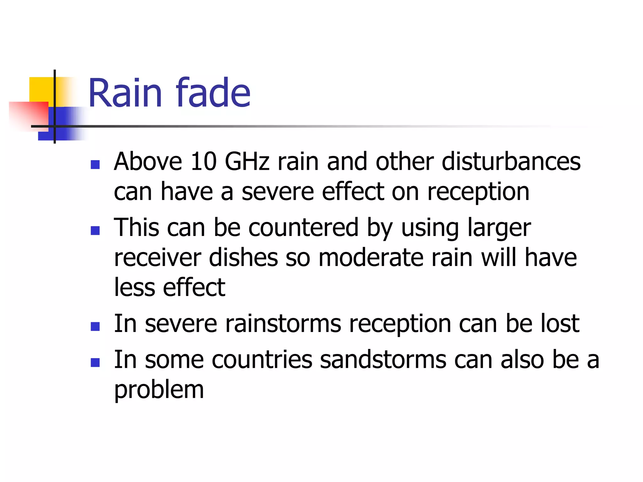
Rain attenuation: This important factor increases with
frequency and rain rate. Additional fade margin is required
for Ku- and Ka-band links, based on the statistics of local
rainfall. This will require careful study for services that
demand high availability, as suggested in Figures 2.4 and
2.5. A standardized rain attenuation predictor, called the
DAH model is available for this purpose [1]. Rain also
introduces scintillation due to scattering of electromagnetic
waves by raindrops, and in a later section we will see that
the raindrops also radiate thermal noise—a factor that is
easily modeled. In addition, rain beading on antenna
surfaces scatters and in very heavy rains can puddle on
feeds, temporarily providing high losses not accounted for in
the DAH and thermal noise models.](https://image.slidesharecdn.com/iarescppt-221123112309-7db8c71d/75/IARE_SC_PPT-pdf-150-2048.jpg)

![Earth’s atmosphere
Source: All about GPS
[www.kowoma.de]](https://image.slidesharecdn.com/iarescppt-221123112309-7db8c71d/75/IARE_SC_PPT-pdf-216-2048.jpg)
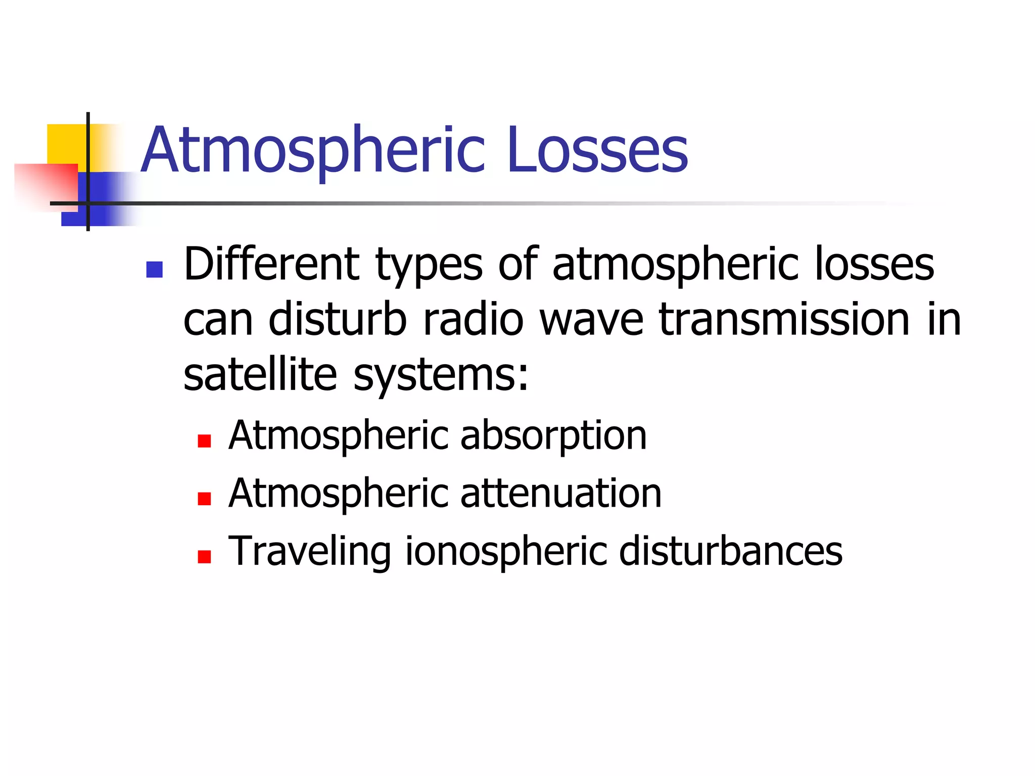
![Atmospheric Absorption
Energy absorption by atmospheric
gases, which varies with the
frequency of the radio waves.
Two absorption peaks are observed
(for 90º elevation angle):
22.3 GHz from resonance
absorption in water vapour (H2O)
60 GHz from resonance absorption
in oxygen (O2)
For other elevation angles:
[AA] = [AA]90 cosec ](https://image.slidesharecdn.com/iarescppt-221123112309-7db8c71d/75/IARE_SC_PPT-pdf-218-2048.jpg)
![Atmospheric Attenuation
Rain is the main cause of atmospheric attenuation (hail, ice and
snow have little effect on attenuation because of their low water
content).
Total attenuation from rain can be determined by:
A = L [dB]
where [dB/km] is called the specific attenuation, and can
be calculated from specific attenuation coefficients in tabular
form that can be found in a number of publications
where L [km] is the effective path length of the signal
through the rain; note that this differs from the geometric
path length due to fluctuations in the rain density.](https://image.slidesharecdn.com/iarescppt-221123112309-7db8c71d/75/IARE_SC_PPT-pdf-219-2048.jpg)
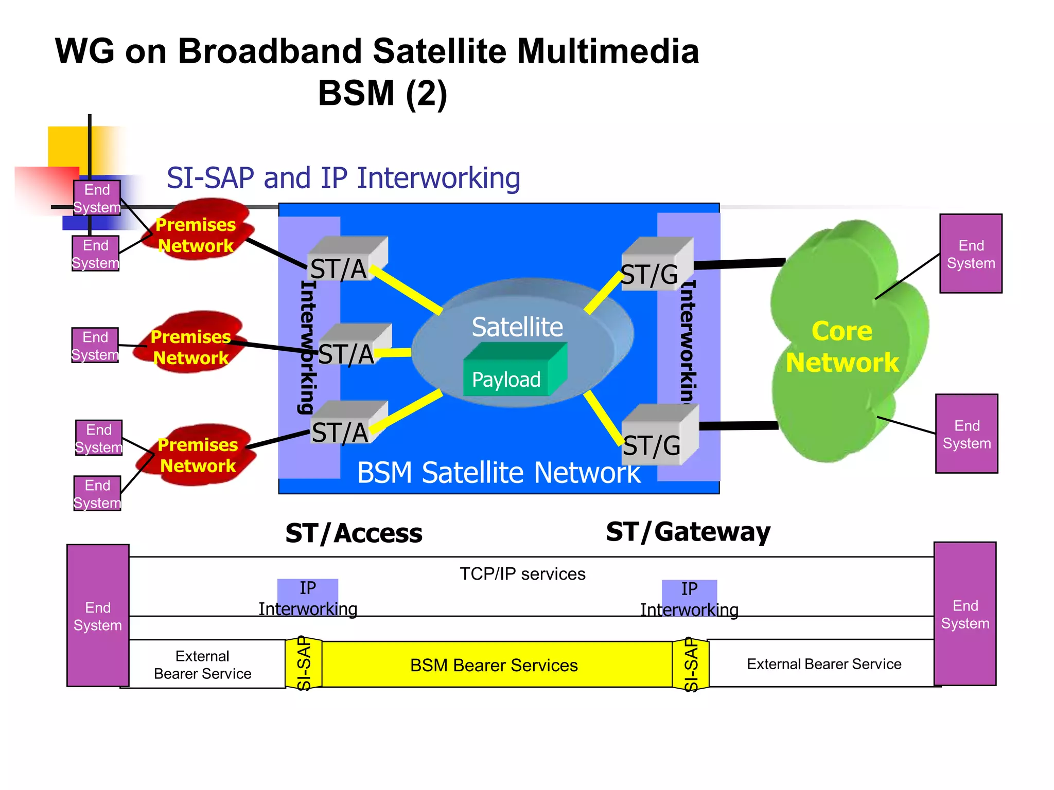
![IP Interworking standards # 1 (TS completed)
SI-SAP specification [TS 102 357; TR 102 353]
First release giving functional organisation of SI-SAP
TR provides SI-SAP guidelines
BSM functional architecture [TS 102 292]
Generic functional architecture
Defines the SI-SAP and the associated adaptation functions for IP interworking
BSM multicast functional architecture [TS 102 294]
Satellite specific functions for multicast services
IGMP adaptation [TS 102 293]
Adaptation of IGMP messages
Can be combined with IGMP proxies and snooping
BSM Traffic Classes [TS 102 295]
Common Traffic classes for IP interworking
WG on Broadband Satellite Multimedia
BSM (5)](https://image.slidesharecdn.com/iarescppt-221123112309-7db8c71d/75/IARE_SC_PPT-pdf-259-2048.jpg)