Hyundai R180W-9A Wheeled Excavator Operator Manual.pdf

Hyundai R180W-9A Wheeled Excavator Operator Manual This manual contains high quality images, circuit diagrams, instructions to help you to maintenance, troubleshooting, diagnostic, and repair your truck This manual contains high quality images, instructions to help you to troubleshoot, and repair your truck. This document is printable, without restrictions, contains searchable text, bookmarks, crosslinks for easy navigation. This manual contains high quality images, circuit diagrams, instructions to help you to operate, maintenance, diagnostic, and repair your truck. This document is printable, without restrictions, contains searchable text. Maintenance Engine Control System Mechanical Fuel Service Specifications Emission Control Intake Exhaust Cooling Lube Ignition Starting Charging Auto Transmission Clutch Manual Transmission Transfer Propeller Shaft Drive Shaft Differential Axle Suspension Tire & Wheel Brake Control Brake Parking Brake Steering Column Power Steering Air Condition Suppl Restraint System Seat Belt Engine Immobilizer Cruise Control Wiper & Washer Door Lock Meter Audio/Visual Horn Windshield/Glass Mirror Instrument Panel Seat Engine Hood/ Door Exterior & Interior Electrical Multiplex/ Can Communication And much more...

Recommended
Recommended
More Related Content
Similar to Hyundai R180W-9A Wheeled Excavator Operator Manual.pdf
Similar to Hyundai R180W-9A Wheeled Excavator Operator Manual.pdf (7)
More from Excavator
More from Excavator (20)
Recently uploaded
Recently uploaded (20)
Hyundai R180W-9A Wheeled Excavator Operator Manual.pdf
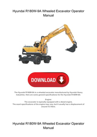
- 1. Hyundai R180W-9A Wheeled Excavator Operator Manual The Hyundai R180W-9A is a wheeled excavator manufactured by Hyundai Heavy Industries. Here are some general specifications for the Hyundai R180W-9A: Engine: The excavator is typically equipped with a diesel engine. The exact specifications of the engine may vary, but it usually has a displacement of around 4.5 liters. Hyundai R180W-9A Wheeled Excavator Operator Manual
- 2. SECTION 1 GENERAL SECTION 1 GENERAL Group 1 Safety Hints -------------------------------------------------------------------------------------------------------- 1-1 Group 2 Specifications ----------------------------------------------------------------------------------------------------- 1-9
- 3. 1-1 FOLLOW SAFE PROCEDURE FOLLOW SAFE PROCEDURE Unsafe work practices are dangerous. Understand service procedure before doing work; do not attempt shortcuts. WEAR PROTECTIVE CLOTHING WEAR PROTECTIVE CLOTHING Wear close fitting clothing and safety equipment appropriate to the job. WARN OTHERS OF SERVICE WORK WARN OTHERS OF SERVICE WORK Unexpected machine movement can cause serious injury. Before performing any work on the excavator, attach a 「Do Not Operate」 tag on the right side control lever. USE HANDHOLDS AND STEPS USE HANDHOLDS AND STEPS Falling is one of the major causes of personal injury. When you get on and off the machine, always maintain a three point contact with the steps and handrails and face the machine. Do not use any controls as handholds. Never jump on or off the machine. Never mount or dismount a moving machine. Be careful of slippery conditions on platforms, steps, and handrails when leaving the machine. SECTION 1 GENERAL SECTION 1 GENERAL GROUP 1 SAFETY GROUP 1 SAFETY 13031GE01 13031GE02 13031GE03
- 4. 1-2 PREPARE FOR EMERGENCIES PREPARE FOR EMERGENCIES Be prepared if a fire starts. Keep a first aid kit and fire extinguisher handy. Keep emergency numbers for doctors, ambulance service, hospital, and fire department near your telephone. PROTECT AGAINST FLYING DEBRIS PROTECT AGAINST FLYING DEBRIS Guard against injury from flying pieces of metal or debris; wear goggles or safety glasses. PROTECT AGAINST NOISE PROTECT AGAINST NOISE Prolonged exposure to loud noise can cause impairment or loss of hearing. Wear a suitable hearing protective device such as ear- muffs or earplugs to protect against objectionable or uncomfortable loud noises. AVOID POWER LINES AVOID POWER LINES Serious injury or death can result from contact with electric lines. Never move any part of the machine or load closer to electric line than 3m(10ft) plus twice the line insulator length. 13031GE05 13031GE06 14W7A1GE07 13031GE04
- 5. 1-3 KEEP RIDERS OFF EXCAVATOR KEEP RIDERS OFF EXCAVATOR Only allow the operator on the excavator. Keep riders off. Riders on excavator are subject to injury such as being struck by foreign objects and being thrown off the excavator. Riders also obstruct the operator's view resulting in the excavator being operated in an unsafe manner. MOVE AND OPERATE MACHINE SAFELY MOVE AND OPERATE MACHINE SAFELY Bystanders can be run over. Know the location of bystanders before moving, swinging, or operating the machine. Always keep the travel alarm in working condition. It warns people when the excavator starts to move. Use a signal person when moving, swinging, or operating the machine in congested areas. Coordinate hand signals before starting the excavator. OPERATE ONLY FORM OPERATOR'S SEAT OPERATE ONLY FORM OPERATOR'S SEAT Avoid possible injury machine damage. Do not start engine by shorting across starter terminals. NEVER start engine while standing on ground. Start engine only from operator's seat. PARK MACHINE SAFELY PARK MACHINE SAFELY Before working on the machine: ·Park machine on a level surface. ·Lower bucket to the ground. ·Turn auto idle switch off. ·Run engine at 1/2 speed without load for 2 minutes. ·Turn key switch to OFF to stop engine. Remove key from switch. ·Move pilot control shutoff lever to locked position. ·Allow engine to cool. 14W7A1GE08 14W7A1GE09 13031GE26
- 6. 1-4 SUPPORT MACHINE PROPERLY SUPPORT MACHINE PROPERLY Always lower the attachment or implement to the ground before you work on the machine. If you must work on a lifted machine or attachment, securely support the machine or attachment. Do not support the machine on cinder blocks, hollow tiles, or props that may crumble under continuous load. Do not work under a machine that is supported solely by a jack. Follow recommended procedures in this manual. SERVICE COOLING SYSTEM SAFELY SERVICE COOLING SYSTEM SAFELY Explosive release of fluids from pressurized cooling system can cause serious burns. Shut off engine. Only remove filler cap when cool enough to touch with bare hands. HANDLE FLUIDS SAFELY-AVOID FIRES HANDLE FLUIDS SAFELY-AVOID FIRES Handle fuel with care; it is highly flammable. Do not refuel the machine while smoking or when near open flame or sparks. Always stop engine before refueling machine. Fill fuel tank outdoors. Store flammable fluids away from fire hazards. Do not incinerate or puncture pressurized containers. Make sure machine is clean of trash, grease, and debris. Do not store oily rags ; they can ignite and burn spontaneously. 13031GE10 13031GE11 13031GE12 13031GE13
- 7. 1-5 BEWARE OF EXHAUST FUMES BEWARE OF EXHAUST FUMES Prevent asphyxiation. Engine exhaust fumes can cause sickness or death. If you must operate in a building, be positive there is adequate ventilation. Either use an exhaust pipe extension to remove the exhaust fumes or open doors and windows to bring enough outside air into the area. REMOVE PAINT BEFORE WELDING OR REMOVE PAINT BEFORE WELDING OR HEATING HEATING Avoid potentially toxic fumes and dust. Hazardous fumes can be generated when paint is heated by welding, soldering, or using a torch. Do all work outside or in a well ventilated area. Dispose of paint and solvent properly. Remove paint before welding or heating: ·If you sand or grind paint, avoid breathing the dust. Wear an approved respirator. ·If you use solvent or paint stripper, remove stripper with soap and water before welding. Remove solvent or paint stripper containers and other flammable material from area. Allow fumes to disperse at least 15 minutes before welding or heating. ILLUMINATE WORK AREA SAFELY ILLUMINATE WORK AREA SAFELY Illuminate your work area adequately but safely. Use a portable safety light for working inside or under the machine. Make sure the bulb is enclosed by a wire cage. The hot filament of an accidentally broken bulb can ignite spilled fuel or oil. 13031GE14 13031GE15
- 8. 1-6 SERVICE MACHINE SAFELY SERVICE MACHINE SAFELY Tie long hair behind your head. Do not wear a necktie, scarf, loose clothing or necklace when you work near machine tools or moving parts. If these items were to get caught, severe injury could result. Remove rings and other jewelry to prevent electrical shorts and entanglement in moving parts. STAY CLEAR OF MOVING PARTS STAY CLEAR OF MOVING PARTS Entanglements in moving parts can cause serious injury. To prevent accidents, use care when working around rotating parts. AVOID HIGH PRESSURE FLUIDS AVOID HIGH PRESSURE FLUIDS Escaping fluid under pressure can penetrate the skin causing serious injury. Avoid the hazard by relieving pressure before disconnecting hydraulic or other lines. Tighten all connections before applying pressure. Search for leaks with a piece of cardboard. Protect hands and body from high pressure fluids. If an accident occurs, see a doctor immediately. Any fluid injected into the skin must be surgically removed within a few hours or gangrene may result. 13031GE16 13031GE17 13031GE18 13031GE19
- 9. 1-7 AVOID HEATING NEAR PRESSURIZED AVOID HEATING NEAR PRESSURIZED FLUID LINES FLUID LINES Flammable spray can be generated by heating near pressurized fluid lines, resulting in severe burns to yourself and bystanders. Do not heat by welding, soldering, or using a torch near pressurized fluid lines or other flammable materials. Pressurized lines can be accidentally cut when heat goes beyond the immediate flame area. Install fire resisting guards to protect hoses or other materials. PREVENT BATTERY EXPLOSIONS PREVENT BATTERY EXPLOSIONS Keep sparks, lighted matches, and flame away from the top of battery. Battery gas can explode. Never check battery charge by placing a metal object across the posts. Use a volt-meter or hydrometer. Do not charge a frozen battery; it may explode. Warm battery to 16˚C(60˚F). 13031GE20 13031GE21 13031GE22 PREVENT ACID BURNS PREVENT ACID BURNS Sulfuric acid in battery electrolyte is poisonous. It is strong enough to burn skin, eat holes in clothing, and cause blindness if splashed into eyes. Avoid the hazard by: 1. Filling batteries in a well-ventilated area. 2.Wearing eye protection and rubber gloves. 3. Avoiding breathing fumes when electrolyte is added. 4. Avoiding spilling of dripping electrolyte. 5. Use proper jump start procedure. If you spill acid on yourself: 1. Flush your skin with water. 2. Apply baking soda or lime to help neutralize the acid. 3. Flush your eyes with water for 10-15 minutes. Get medical attention immediately. If acid is swallowed: 1. Drink large amounts of water or milk. 2. Then drink milk of magnesia, beaten eggs, or vegetable oil. 3. Get medical attention immediately.
- 10. 1-8 USE TOOLS PROPERLY USE TOOLS PROPERLY Use tools appropriate to the work. Makeshift tools, parts, and procedures can create safety hazards. Use power tools only to loosen threaded tools and fasteners. For loosening and tightening hardware, use the correct size tools. DO NOT use U.S. measurement tools on metric fasteners. Avoid bodily injury caused by slipping wrenches. Use only recommended replacement parts. (See Parts manual.) DISPOSE OF FLUIDS PROPERLY DISPOSE OF FLUIDS PROPERLY Improperly disposing of fluids can harm the environment and ecology. Before draining any fluids, find out the proper way to dispose of waste from your local environmental agency. Use proper containers when draining fluids. Do not use food or beverage containers that may mislead someone into drinking from them. DO NOT pour oil into the ground, down a drain, or into a stream, pond, or lake. Observe relevant environmental protection regulations when disposing of oil, fuel, coolant, brake fluid, filters, batteries, and other harmful waste. REPLACE SAFETY SIGNS REPLACE SAFETY SIGNS Replace missing or damaged safety signs. See the machine operator's manual for correct safety sign placement. LIVE WITH SAFETY LIVE WITH SAFETY Before returning machine to customer, make sure machine is functioning properly, especially the safety systems. Install all guards and shields. 13031GE23 13031GE24 13031GE25
- 11. 1-9 GROUP 2 SPECIFICATIONS GROUP 2 SPECIFICATIONS 1. MAJOR COMPONENT 1. MAJOR COMPONENT Battery box Boom Boom cylinder Cab Arm cylinder Arm Counterweight Connecting link Front axle Bucket cylinder Front drive shaft Travel motor Transmission Oil cooler Dozer blade Rear drive shaft Rear axle Tool box Bucket Tooth Fuel tank Hydraulic tank Turning joint Swing motor Main pump Engine Radiator Main control valve Dozer cylinder Muffler Tire Side cutter Connecting rod Swing bearing After treatment device Outrigger 180W9A2SP01 Connecting rod
- 12. 1-10 2. SPECIFICATIONS 2. SPECIFICATIONS 5.2 5.2 m (17' 1") ONE PIECE BOOM, 2.6 (17' 1") ONE PIECE BOOM, 2.6 m (8' 6") (8' 6") ARM AND REAR DOZER BLADE ARM AND REAR DOZER BLADE 1) 1) Description Unit Specification Operating weight kg (lb) 17300 (38140) Bucket capacity (SAE heaped), standard m3 (yd3) 0.76 (0.99) Overall length A mm (ft-in) 8650 (28' 5") Overall width B 2500 (8' 2") Overall height C 3610 (11' 10") Upperstructure width D 2475 (8' 1") Cab height E 3190 (10' 6") Ground clearance of counterweight F 1270 (4' 2") Engine cover height G 2520 (8' 3") Minimum ground clearance H 340 (1' 1") Rear-end distance I 2480 (8' 2") Rear-end swing radius I' 2480 (8' 2") Wheel base J 2600 (8' 6") Tread K 1914 (6' 3") Dozer blade width L 2500 (8' 2") Travel speed Low km/hr (mph) 10 (6.2) High 36 (23.0) Creep 3.0 (1.9) Swing speed rpm 11.0 Gradeability Degree (%) 35 (70) Max traction force kgf (lbf) 9440 (20810) E D K B(L) C I(I') G A F J H 17W92SP02
- 13. 1-11 5.1 5.1 m (16' 9") (16' 9") HYDRAULIC ADJUSTABLE BOOM HYDRAULIC ADJUSTABLE BOOM, 2.6 , 2.6 m (8' 6") (8' 6") ARM AND REAR DOZER ARM AND REAR DOZER BLADE BLADE 2) 2) E D K B(L) C I(I') G A F J H 17W92SP03 Description Unit Specification Operating weight kg (lb) 17750 (39130) Bucket capacity (SAE heaped), standard m3 (yd3) 0.76 (0.99) Overall length A mm (ft-in) 8750 (28' 8") Overall width B 2500 (8' 2") Overall height C 2920 (9' 7") Upperstructure width D 2475 (8' 1") Cab height E 3190 (10' 6") Ground clearance of counterweight F 1270 (4' 2") Engine cover height G 2610 (8' 7") Minimum ground clearance H 340 ( 1' 1") Rear-end distance I 2480 (8' 2") Rear-end swing radius I' 2480 (8' 2") Wheel base J 2600 (8' 6") Tread K 1914 (6' 3") Dozer blade width L 2500 (8' 2") Travel speed Low km/hr (mph) 9.5 (5.9) High 35 (21.7) Creep 3.0 (1.9) Swing speed rpm 9.1 Gradeability Degree (%) 30 (58) Max traction force kgf (lbf) 11000 (24250)
- 14. 1-12 3. WORKING RANGE 3. WORKING RANGE 5.2 5.2 m (17' 1") MONO BOOM (17' 1") MONO BOOM 1) 1) [ ] : Power boost D E A F B B' C 8ft A' 17W92SP05 Description 2.2m (7' 3")Arm 2.6m (8' 6")Arm 3.1 m (10' 2") Arm Max digging reach A 8820 mm (29' 1") 9200 mm (30' 3") 9450 mm (31' 0") Max digging reach on ground A' 8615 mm (28' 4") 9000 mm (29' 7") 9250 mm (30' 4") Max digging depth B 5500 mm (18' 2") 5900 mm (19' 5") 6320 mm (20' 9") Max digging depth (8 ft level) B' 5280 mm (17' 5") 5700 mm (18' 9") 6130 mm (20' 1") Max vertical wall digging depth C 4850 mm (16' 1") 5310 mm (17' 6") 5470 mm (17' 11") Max digging height D 9180 mm (30' 3") 9300 mm (30' 7") 9220 mm (30' 3") Max dumping height E 6520 mm (21' 5") 6660 mm (21' 10") 6620 mm (21' 9") Min swing radius F 3290 mm (10' 9") 3230 mm (10' 8") 3160 mm (10' 4") Bucket digging force SAE 107.9 [117.2] kN 107.9 [117.2] kN 107.9 [117.2] kN 11000 [11940] kgf 11000 [11940] kgf 11000 [11940] kgf 24250 [26330] lbf 24250 [26330] lbf 24250 [26330] lbf ISO 123.6 [134.2] kN 123.6 [134.2] kN 123.6 [134.2] kN 12600 [13680] kgf 12600 [13680] kgf 12600 [13680] kgf 27780 [30160] lbf 27780 [30160] lbf 27780 [30160] lbf Arm digging force SAE 87.2 [94.7] kN 77.3 [83.9] kN 69.0 [74.9] kN 8890 [9650] kgf 7880 [8560] kgf 7030 [7630] kgf 19600 [21280] lbf 17370 [18860] lbf 15500 [16830] lbf ISO 91.0 [98.8] kN 80.3 [87.2] kN 71.4 [77.5] kN 9280 [10080] kgf 8190 [8890] kgf 7280 [7900] kgf 20460 [22210] lbf 18060 [19600] lbf 16050 [17430] lbf
- 15. 1-13 5.1 5.1 m (16' 9") HYDRAULIC ADJUSTABLE BOOM (16' 9") HYDRAULIC ADJUSTABLE BOOM 2) 2) [ ] : Power boost B B' C D E A A' F 8ft 17W92SP06 Description 2.2 m (7' 3") Arm 2.6 m (8' 6") Arm Max digging reach A 8760 mm (28' 9") 9110 mm (29' 11") Max digging reach on ground A' 8550 mm (28' 1") 8910 mm (29' 3") Max digging depth B 5220 mm (17' 2") 5620 mm (18' 5") Max digging depth (8 ft level) B' 5120 mm (16' 10") 5520 mm (18' 1") Max vertical wall digging depth C 4430 mm (14' 6") 4780 mm (15' 8") Max digging height D 9630 mm (31' 7") 9820 mm (32' 3") Max dumping height E 6930 mm (22' 9") 7130 mm (23' 5") Min swing radius F 3100 mm (10' 2") 2970 mm (9' 9") Bucket digging force SAE 107.9 [117.2] kN 107.9 [117.2] kN 11000 [11940] kgf 11000 [11940] kgf 24250 [26330] lbf 24250 [26330] lbf ISO 123.6 [134.2] kN 123.6 [134.2] kN 12600 [13680] kgf 12600 [13680] kgf 27780 [30160] lbf 27780 [30160] lbf Arm digging force SAE 87.2 [94.7] kN 77.3 [83.9] kN 8890 [9650] kgf 7880 [8560] kgf 19600 [21280] lbf 17370 [18860] lbf ISO 91.0 [98.8] kN 80.3 [87.2] kN 9280 [10080] kgf 8190 [8890] kgf 20460 [22210] lbf 18060 [19600] lbf
- 16. 1-14 4. WEIGHT 4. WEIGHT Item R180W-9A kg lb Upperstructure assembly 4590 10120 Main frame weld assembly 1430 3150 Engine assembly 520 1150 Fan clutch assembly 45 100 Main pump assembly 90 200 Main control valve assembly 135 300 Swing motor assembly 240 530 Hydraulic oil tank assembly 165 360 Fuel tank assembly 130 290 Counterweight 3150 6940 Cab assembly 500 1100 Lower frame weld assembly 1640 3615 Swing bearing 260 570 Travel motor assembly 80 176 Turning joint 120 265 Transmission assembly 135 298 Front axle assembly 655 1444 Rear axle assembly 534 1177 Front attachment assembly (5.2 m boom, 2.6 m arm, 0.76 m3 SAE heaped bucket) 3060 6750 5.2 m boom assembly 1060 2340 2.6 m arm assembly 535 1180 0.76 m3 SAE heaped bucket assembly 570 1260 Boom cylinder assembly 155×2EA 340×2EA Arm cylinder assembly 180 400 Bucket cylinder assembly 125 260 Bucket control link assembly 120 265 Oscillating cylinder assembly 30 70 Dozer blade assembly 830 1830 Blade cylinder assembly 55×2EA 120×2EA Front outrigger assembly 1000 2200 Rear outrigger assembly 1010 2230 Outrigger cylinder assembly 80 180
- 17. 1-15 5. LIFTING CAPACITIES 5. LIFTING CAPACITIES ROBEX 180W-9A ROBEX 180W-9A 5.2 m (17' 1") boom, 2.6 m (8' 6") arm equipped with 0.76 m3 (SAE heaped) bucket, rear dozer blade down and 3150 kg (6940 lb) counterweight. 1) 1) (1) Note 1. 2. 3. 4. Lifting capacity are based on SAE J1097 and ISO 10567. Lifting capacity of the ROBEX series does not exceed 75% of tipping load with the machine on firm, level ground or 87% of full hydraulic capacity. The load point is a hook located on the back of the bucket. * indicates load limited by hydraulic capacity. · : Rating over-front : Rating over-side or 360 degree · Load point height Load radius At max. reach 1.5 m (5.0 ft) 3.0 m (10.0 ft) 4.5 m (15.0 ft) 6.0 m (20.0 ft) 7.5 m (25.0 ft) Capacity Reach m (ft) 7.5 m kg *3340 2710 6.57 (25.0 ft) lb *7360 5970 (21.6) 6.0 m kg *3380 3130 *3320 1970 7.70 (20.0 ft) lb *7450 6900 *7320 4340 (25.3) 4.5 m kg *3800 3030 *1830 *1830 *3360 1640 8.35 (15.0 ft) lb *8380 6680 *4030 *4030 *7410 3620 (27.4) 3.0 m kg *8730 8720 *5560 4570 *4380 2860 *3290 1920 3320 1470 8.66 (10.0 ft) lb *19250 19220 *12260 10080 *9660 6310 *7250 4230 7320 3240 (28.4) 1.5 m kg *6780 *6780 *6840 4180 *4990 2680 *4070 1840 3270 1430 8.67 (5.0 ft) lb *14950 *14950 *15080 9220 *11000 5910 *8970 4060 7210 3150 (28.4) Ground kg *7720 7470 *7540 3950 *5400 2550 *3830 1780 3430 1500 8.37 Line lb *17020 16470 *16620 8710 *11900 5620 *8440 3920 7560 3310 (27.5) -1.5 m kg *7000 *7000 *10750 7480 *7530 3880 *5400 2500 *3670 1730 7.73 (-5.0 ft) lb *15430 *15430 *23700 16490 *16600 8550 *11900 5510 *8090 3810 (25.4) -3.0 m kg *10290 *10290 *9880 7620 *6750 3920 *4710 2540 *3540 2280 6.63 (-10.0 ft) lb *22690 *22690 *21780 16800 *14880 8640 *10380 5600 *7800 5030 (21.8) -4.5 m kg *6890 *6890 *4530 4130 (-15.0 ft) lb *15190 *15190 *9990 9110
- 18. 1-16 5.2 m (17' 1") boom, 2.2 m (7' 3") arm equipped with 0.76 m3 (SAE heaped) bucket, rear dozer blade down and 3150 kg (6940 lb) counterweight. (2) 5.1 m (16' 9") hydraulic adjustable boom, 2.6 m (8' 6") arm equipped with 0.76 m3 (SAE heaped) bucket, rear dozer blade down and 3150 kg (6940 lb) counterweight. (3) Load point height Load radius At max. reach 1.5 m (5.0 ft) 3.0 m (10.0 ft) 4.5 m (15.0 ft) 6.0 m (20.0 ft) 7.0 m (25.0 ft) Capacity Reach m (ft) 6.0 m kg *3410 2000 7.63 (20.0 ft) lb *7520 4410 (25.0) 4.5 m kg *3410 1650 8.29 (15.0 ft) lb *7520 3640 (27.2) 3.0 m kg *4420 2870 *3380 1910 3400 1480 8.60 (10.0 ft) lb *9740 6330 *7450 4210 7500 3260 (28.2) 1.5 m kg *6600 *6600 *6800 4200 *4980 2680 *4050 1830 3350 1440 8.61 (5.0 ft) lb *14550 *14550 *14990 9260 *10980 5910 *8930 4030 7390 3170 (28.2) Ground kg *6550 *6550 *7410 *7410 *7460 3950 *5340 2550 *3830 1780 3530 1520 8.31 Line lb *14440 *14440 *16340 *16340 *16450 8710 *11770 5620 *8440 3920 7780 3350 (27.3) -1.5 m kg *10160 *10160 *10600 7470 *7390 3870 *5290 2490 *3520 1760 7.66 (-5.0 ft) lb *22400 *22400 *23370 16470 *16290 8530 *11660 5490 *7760 3880 (25.1) -3.0 m kg *9480 7640 *6500 3930 *4440 2550 *3240 2350 6.54 (-10.0 ft) lb *20900 16840 *14330 8660 *9790 5620 *7140 5180 (21.5) -4.5 m kg *6100 *6100 *3870 *3870 (-15.0 ft) lb *13450 *13450 *8530 *8530 Load point height Load radius At max. reach 1.5 m (5.0 ft) 3.0 m (10.0 ft) 4.5 m (15.0 ft) 6.0 m (20.0 ft) 7.5 m (25.0 ft) Capacity Reach m (ft) 7.5 m kg *3680 3080 6.09 (25.0 ft) lb *8110 6790 (20.0) 6.0 m kg *3630 3080 *3610 2180 7.30 (20.0 ft) lb *8000 6790 *7960 4810 (24.0) 4.5 m kg *4750 *4750 *4130 3010 *3630 1790 8.00 (15.0 ft) lb *10470 *10470 *9110 6640 *8000 3950 (26.2) 3.0 m kg *6020 4520 *4660 2860 *2670 1920 3560 1610 8.32 (10.0 ft) lb *13270 9960 *10270 6310 *5890 4230 7850 3550 (27.3) 1.5 m kg *7180 4170 *5210 2700 *3480 1860 3520 1570 8.33 (5.0 ft) lb *15830 9190 *11490 5950 *7670 4100 7760 3460 (27.3) Ground kg *7120 *7120 *7680 3990 *5510 2590 3720 1660 8.01 Line lb *15700 *15700 *16930 8800 *12150 5710 8200 3660 (26.3) -1.5 m kg *7410 *7410 *10980 7610 *7470 3950 *5370 2560 *3810 1940 7.34 (-5.0 ft) lb *16340 *16340 *24210 16780 *16470 8710 *11840 5640 *8400 4280 (24.1) -3.0 m kg *11630 *11630 *9190 7790 *6420 4030 *3510 2650 6.15 (-10.0 ft) lb *25640 *25640 *20260 17170 *14150 8880 *7740 5840 (20.2) Note 1. 2. 3. 4. Lifting capacity are based on SAE J1097 and ISO 10567. Lifting capacity of the ROBEX series does not exceed 75% of tipping load with the machine on firm, level ground or 87% of full hydraulic capacity. The load point is a hook located on the back of the bucket. * indicates load limited by hydraulic capacity.
- 19. 1-17 6. BUCKET SELECTION GUIDE 6. BUCKET SELECTION GUIDE GENERAL BUCKET GENERAL BUCKET 1) 1) Applicable for materials with density of 2000 kg/m3 (3370 lb/yd3) or less Applicable for materials with density of 1600 kg/m3 (2700 lb/yd3) or less Applicable for materials with density of 1100 kg/m3 (1850 lb/yd3) or less ※ : Standard bucket ◈ : Heavy duty bucket 0.39 m3 SAE heaped bucket 0.50 m3 SAE heaped bucket 0.64 m3, ※0.76 m3 SAE heaped bucket 0.89 m3, 1.05 m3 SAE heaped bucket ◈0.69 m3 SAE heaped bucket Capacity Width Weight Recommendation 5.1 m (16' 9") Mono boom 5.1 m (16' 9") Hyd adjustable boom SAE heaped CECE heaped Without side cutter With side cutter 2.2marm (7' 3") 2.6marm (8' 6") 3.1marm (10' 2") 2.2marm (7' 3") 2.6marm (8' 6") 0.39m3 (0.51yd3) 0.34m3 (0.44yd3) 620mm (24.4") 740mm (29.1") 410 kg (900 lb) 0.50m3 (0.65yd3) 0.44m3 (0.58yd3) 760mm (29.9") 880mm (34.6") 470 kg (1040 lb) 0.64m3 (0.84yd3) 0.55m3 (0.72yd3) 920mm (36.2") 1040mm (40.9") 510 kg (1120 lb) *0.76m3 (0.99 yd3) 0.65m3 (0.85yd3) 1060mm (41.7") 1180mm (46.5") 570 kg (1260 lb) 0.89m3 (1.16yd3) 0.77m3 (1.01yd3) 1220mm (48.0") 1340mm (52.8") 610 kg (1340 lb) 1.05m3 (1.37yd3) 0.90m3 (1.18yd3) 1400mm (55.1") 1520mm (59.8") 680 kg (1500 lb) ◈0.69m3 (0.9yd3) 0.62m3 (0.81yd3) 990mm (39.0") - 700 kg (1540 lb)
- 20. 1-18 7. SPECIFICATIONS FOR MAJOR COMPONENTS 7. SPECIFICATIONS FOR MAJOR COMPONENTS ENGINE ENGINE 1) 1) MAIN PUMP MAIN PUMP 2) 2) [ ]: Power boost Item Specification Model Cummins QSB 6.7 Type 4-cycle turbocharged diesel engine, low emission Cooling method Water cooling Number of cylinders and arrangement 6 cylinders, in-line Firing order 1-5-3-6-2-4 Combustion chamber type Direct injection type Cylinder bore×stroke 107×124 mm (4.2"×4.9") Piston displacement 6700 cc (409 cu in) Compression ratio 17.3 : 1 Rated gross horse power (SAE J1995) 165 Hp (123 kW) at 2200 rpm Maximum torque 74.7 kgf·m (540 lbf·ft) at 1500 rpm Engine oil quantity 23.7ℓ (6.3 U.S. gal) Dry weight 520 kg (1145 lb) High idling speed 2200±50 rpm Low idling speed 850±100 rpm Rated fuel consumption 167.0 g/Hp·hr at 2200 rpm Starting motor Nippon densor (24 V-4.8 kW) Alternator Delco remy (24 V-95 A) Battery 2×12 V×100 Ah Item Specification Type Variable displacement tandem axis piston pumps Capacity 2×80 cc/rev Maximum pressure 350 kgf/cm2 (4980 psi) [380 kgf/cm2 (5400 psi)] Rated oil flow 2×172ℓ/min (45.4 U.S. gpm / 37.8 U.K. gpm) Rated speed 2150 rpm
- 21. 1-19 TRAVEL MOTOR TRAVEL MOTOR GEAR PUMP GEAR PUMP MAIN CONTROL VALVE MAIN CONTROL VALVE SWING MOTOR SWING MOTOR 6) 6) 3) 3) 4) 4) 5) 5) [ ]: Power boost Item Specification Type Fixed displacement gear pump single stage Capacity 15cc/rev Maximum pressure 40 kgf/cm2 (570 psi) Rated oil flow 32.3ℓ/min (8.5 U.S. gpm/7.1 U.K. gpm) Item Specification Type 11 spools two-block Operating method Hydraulic pilot system Main relief valve pressure 350 kgf/cm2 (4980 psi) [380 kgf/cm2 (5400 psi)] Overload relief valve pressure 400 kgf/cm2 (5690 psi) Item Specification Type Fixed displacement axial piston motor Capacity 117.8 cc/rev Relief pressure 285 kgf/cm2 (4050 psi) Braking system Automatic, spring applied hydraulic released Braking torque 59 kgf·m (427 lbf·ft) Brake release pressure 33~50 kgf/cm2 (469~711 psi) Reduction gear type 2 - stage planetary Item Specification Type Variable displacement bent-axis axial piston motor Relief pressure 380 kgf/cm2 (5400 psi) Counter balance valve Applied Capacity 140 cc/rev
- 22. 1-20 CYLINDER CYLINDER POWER TRAIN POWER TRAIN 7) 7) 8) 8) Item Description Specification Transmission Type 2 speed power shift transmission Gear ratio 1st 4.87 2nd 1.20 Parking brake Type Multi disc brake integrated in transmission Maximum braking torque 3044 kgf·m (22020 lbf·ft) Axle Type 4 wheel drive with differential Gear ratio 16.0 Brake Multi disc brake Item Specification Boom cylinder Bore dia×Rod dia×Stroke Ø115×Ø80×1090 mm Cushion Extend only Arm cylinder Bore dia×Rod dia×Stroke Ø120×Ø85×1355 mm Cushion Extend and retract Bucket cylinder Bore dia×Rod dia×Stroke Ø110×Ø75×995 mm Cushion Extend only Dozer cylinder Bore dia×Rod dia×Stroke Ø110×Ø65×235 mm Cushion Extend only Outrigger cylinder Bore dia×Rod dia×Stroke Ø125×Ø75×475 mm Cushion - Adjust boom cylinder Bore dia×Rod dia×Stroke Ø115×Ø80×960 mm Cushion Extend only ◈ : Heavy duty bucket BUCKET BUCKET Item Capacity Tooth quantity Width SAE heaped CECE heaped Without side cutter With side cutter R180W-9A 0.76 m3 (0.99 yd3) 0.65 m3 (0.85 yd3) 5 1060 mm (41.7") 1180 mm (46.5") 0.39 m3 (0.51 yd3) 0.34 m3 (0.44 yd3) 3 620 mm (24.4") 740 mm (29.1") 0.50 m3 (0.65 yd3) 0.44 m3 (0.58 yd3) 4 760 mm (29.9") 880 mm (34.6") 0.64 m3 (0.84 yd3) 0.55 m3 (0.72 yd3) 5 920 mm (36.2") 1040 mm (40.9") 0.89 m3 (1.16 yd3) 0.77 m3 (1.01 yd3) 6 1220 mm (48.0") 1340 mm (52.8") 1.05 m3 (1.37 yd3) 0.90 m3 (1.18 yd3) 6 1400 mm (55.1") 1520 mm (59.8") ◈0.69 m3 (0.90 yd3) 0.62 m3 (0.81 yd3) 5 990 mm (39.0") - 9) 9)
- 23. 1-21 8. RECOMMENDED OILS 8. RECOMMENDED OILS Use only oils listed below or equivalent. Use only oils listed below or equivalent. Do not mix different brand oil. Do not mix different brand oil. SAE SAE : Society of Automotive Engineers API API : American Petroleum Institute ISO ISO : International Organization for Standardization NLGI NLGI : National Lubricating Grease Institute ASTM ASTM : American Society of Testing and Materia UTTO UTTO : Universal Tractor Transmission Oil Service point Kind of fluid Capacity ℓ (U.S. gal) Ambient temperature˚C(˚F) Engine oil pan Engine oil 23.7 (6.3) Transmission case 3.0 (0.79) Swing drive Gear oil 5.0 (1.3) Grease 1.2 (0.3) Front axle Gear oil Center : 10.5 (2.8) Hub : 2.5×2 (0.7×2) Rear axle Center : 12.5 (3.3) Hub : 2.5×2 (0.7×2) Hydraulic tank Hydraulic oil Tank: 160 (42.3) System: 270 (71.3) Fuel tank Diesel fuel★1 260 (68.7) Fitting (Grease nipple) Grease As required Radiator (Reservoir tank) Mixture of antifreeze and soft water★2 19.5 (5.2) SAE 85W-90 LSD or UTTO ★NLGI NO.1 NLGI NO.2 ★1 : Ultra low sulfur diesel - sulfur content 15 ppm ★2 : Soft water City water or distilled water ★ : Cold region Russia, CIS, Mongolia SAE 30 SAE 10W SAE 10W-30 SAE 15W-40 SAE 85W-140 ISO VG 46 ISO VG 68 ★ASTM D975 NO.1 ASTM D975 NO.2 ★NLGI NO.1 NLGI NO.2 Ethylene glycol base permanent type (50 : 50) ★SAE 5W-40 ★SAE 75W-90 ★ISO VG 15 ★Ethyleneglycolbasepermanenttype(60:40) -50 -30 -20 -10 0 10 20 30 40 (-58) (-22) (-4) (14) (32) (50) (68) (86) (104) ISO VG 32
- 24. SECTION 2 STRUCTURE AND FUNCTION SECTION 2 STRUCTURE AND FUNCTION Group 1 Pump Device ------------------------------------------------------------------------------------------------------ 2-1 Group 2 Main Control Valve --------------------------------------------------------------------------------------------- 2-20 Group 3 Swing Device ------------------------------------------------------------------------------------------------------ 2-47 Group 4 Travel Motor -------------------------------------------------------------------------------------------------------- 2-58 Group 5 RCV Lever ---------------------------------------------------------------------------------------------------------- 2-64 Group 6 Accelerator Pedal ----------------------------------------------------------------------------------------------- 2-71 Group 7 Brake Pedal -------------------------------------------------------------------------------------------------------- 2-72 Group 8 Transmission ------------------------------------------------------------------------------------------------------- 2-74 Group 9 Travel Control Valve -------------------------------------------------------------------------------------------- 2-81 Group 10 Steering Valve ---------------------------------------------------------------------------------------------------- 2-83
- 25. 2-1 1. STRUCTURE 1. STRUCTURE The pump device consists of main pump, regulator and gear pump. SECTION 2 STRUCTURE AND FUNCTION SECTION 2 STRUCTURE AND FUNCTION GROUP 1 PUMP DEVICE GROUP 1 PUMP DEVICE Pi1 a4 Dr3 B3 A3 A1 A2 Pi1 Pi2 B1 Qmax adjusting screw EPPR valve Front regulator Rear regulator Front pump Valve block Rear pump Gear pump Qmin adjusting screw Qmin adjusting screw P1 Dr2 a3 Pi2 Hydraulic circuit Dr1 A VIEW A A2 A1 a1 a2 B1 a1 a2 A1 A2 Pi2 Pi1 B3 a3 A3 P1 FRONT REAR Dr2 B1 Dr1 a4 Dr3 Dr2 KR38-9N37 KR38-9N35 17W92MP01 Port Port name Port size A1,2 Delivery port SAE6000psi 3/4" B1 Suction port SAE2500psi 2 1/2" Dr1 Drain port PF 3/4 - 20 Dr2 Drain port PF 1/2 - 19 Dr3 Drain port PF 3/8 - 15 Pi1, i2 Pilot port PF 1/4 - 15 P1 EPPR valve primary port PF 1/4 - 15 a1,2,3 Gauge port PF 1/4 - 15 a4 Gauge port PF 1/4 - 14 A3 Gear pump delivery port PF 1/2 - 19 B3 Gear pump suction port PF 3/4 - 20.5
- 26. 2-2 MAIN PUMP (1/2) The main pump consists of two piston pumps(front & rear) and valve block. 1) 1) 111 Drive shaft (F) 113 Drive shaft (R) 116 Gear 123 Roller bearing 124 Needle bearing 127 Bearing spacer 141 Cylinder block 151 Piston 152 Shoe 153 Push-plate 156 Bushing 157 Cylinder spring 211 Shoe plate 212 Swash plate 214 Bushing 251 Support 261 Seal cover (F) 262 Seal cover (R) 271 Pump casing 312 Valve block 313 Valve plate (R) 314 Valve plate (L) 401 Hexagon socket bolt 406 Hexagon socket bolt 466 VP Plug 467 VP Plug 468 VP Plug 490 Plug 531 Tilting pin 532 Servo piston 534 Stopper (L) 535 Stopper (S) 548 Pin 702 O-ring 710 O-ring 711 O-ring 717 O-ring 719 O-ring 724 O-ring 725 O-ring 727 O-ring 728 O-ring 732 O-ring 774 Oil seal 789 Back up ring 792 Back up ring 808 Hexagon head nut 824 Snap ring 885 Pin 886 Spring pin 901 Eye bolt 953 Set screw 954 Set screw 981 Plate 983 Pin 710 406 113 152 151 124 719 312 711 901 954 724 534 792 702 214 548 531 532 732 789 535 808 953 886 717 406 774 111 261 127 123 710 824 251 490 212 211 153 156 157 467 728 468 727 466 725 313 116 885 314 141 981 983 271 401 406 262 808 14W72SF02
- 27. 2-3 MAIN PUMP (2/2) MAIN PUMP (2/2) 04 Gear pump 115 Shaft 117 Gear No. 2 118 Gear No. 3 125 Ball bearing 126 Roller bearing 128 Bearing spacer 262 Cover 284 Plate 326 Gear case 414 Screw 435 Hexagon socket bolt 468 Plug 710 O-ring 711 O-ring 728 O-ring 825 Retainer ring 826 Retainer ring 885 Spring pin 886 Pin 04 826 115 128 262 885 126 326 414 125 711 284 710 825 435 468 728 118 117 FRONT SIDE REAR SIDE 886 14W92MP03
- 28. 2-4 REGULATOR (1/2) REGULATOR (1/2) 2) 2) 412 876 874 A B 755 858 614 615 613 611 A B VIEW C (FRONT) 897 612 641 730 643 708 644 645 646 SECTION B-B 728 924 801 438 P2 KR38-9N37 (FRONT) KR38-9N35 (REAR) A B 413 438 496 724 725 436 D D VIEW C (REAR) 413 438 656 438 722 496 724 725 436 079 735 722 466 755 496 753 SECTION D-D(REAR) P1 a 875 P1 a 405 699 Pi 735 Pi Pi C 753 Pi 14W92MP04 Port Port name Port size A Delivery port 3/4" B Suction port 2 1/2" Pi Pilot port PF 1/4-15 P1 EPPR valve primary port PF 1/4-15 P2 Companion delivery port Internal a Gauge port PF 1/4-15
- 29. 2-5 REGULATOR (2/2) REGULATOR (2/2) 079 EPPR valve assembly 405 Hexagon socket screw 412 Hexagon socket screw 413 Hexagon socket screw 436 Hexagon socket screw 438 Hexagon socket screw 466 Plug 496 Plug 601 Casing 611 Feed back lever 612 Lever (1) 613 Lever (2) 614 Fulcrum plug 615 Adjust plug 621 Compensator piston 622 Piston case 623 Compensator rod 624 Spring seat (C) 625 Outer spring 626 Inner spring 627 Adjust stem (C) 628 Adjust screw (C) 629 Cover (C) 630 Lock nut 631 Sleeve, Pf 641 Pilot cover 643 Pilot piston 644 Spring seat (Q) 645 Adjust stem (Q) 646 Pilot spring 651 Sleeve 652 Spool 653 Spring seat 654 Return spring 655 Set spring 656 Block cover 699 Valve casing 708 O-ring 722 O-ring 724 O-ring 725 O-ring 728 O-ring 730 O-ring 732 O-ring 733 O-ring 734 O-ring 735 O-ring 753 O-ring 754 O-ring 755 O-ring 756 O-ring 763 O-ring 801 Nut 802 Nut 814 Snap ring 836 Snap ring 858 Snap ring 874 Pin 875 Pin 876 Pin 887 Pin 897 Pin 898 Pin 924 Set screw 734 653 654 836 651 652 601 624 629 630 655 641 814 898 631 732 628 756 763 887 626 625 733 622 621 623 754 802 627 SECTION A-A 14W92MP05
- 30. 2-6 GEAR PUMP GEAR PUMP 3) 3) 307 Poppet 308 Seat 309 Spring seat 310 Spring 311 Screw 312 Nut 351 Gear case 353 Drive gear 354 Driven gear 355 Filter 361 Front case 433 Flange socket 434 Flange socket 435 Flange socket 466 Plug 700 Ring 709 O-ring 725 O-ring 732 O-ring 850 Snap ring 887 Pin 434 466,725 435 700 353 351 354 709 361 433 434 311 312 732 310 307 309 308 355 850 Dr3 Dr3 a3 B3 887 A3 14W7A2MP06
- 31. Hyundai R180W-9A Wheeled Excavator Operator Manual The Hyundai R180W-9A is a wheeled excavator manufactured by Hyundai Heavy Industries. Here are some general specifications for the Hyundai R180W-9A: Engine: The excavator is typically equipped with a diesel engine. The exact specifications of the engine may vary, but it usually has a displacement of around 4.5 liters. Hyundai R180W-9A Wheeled Excavator Operator Manual