HYUNDAI HL740 TM-7 LOADER Service Repair Manual-extracted.pdf
•
0 likes•4 views

HYUNDAI HL740 TM-7 LOADER Service Repair Manual-extracted.pdf

Recommended
Recommended
More Related Content
More from Excavator
More from Excavator (20)
Recently uploaded
Recently uploaded (20)
HYUNDAI HL740 TM-7 LOADER Service Repair Manual-extracted.pdf
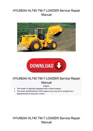
- 1. HYUNDAI HL740 TM-7 LOADER Service Repair Manual HYUNDAI HL740 TM-7 LOADER Service Repair Manual Engine: ● The loader is typically equipped with a diesel engine. ● The exact specifications of the engine may vary, but it usually has a displacement of around 6.7 liters. HYUNDAI HL740 TM-7 LOADER Service Repair Manual
- 2. SECTION 1 GENERAL Group 1 Safety Hints 1-1 Group 2 Specifications 1-10 Group 3 Operational Checkout Record Sheet 1-25
- 3. SECTION 1 GENERAL FOLLOW SAFE PROCEDURE Unsafe work practices are dangerous. Understand service procedure before doing work; Do not attempt shortcuts. WEAR PROTECTIVE CLOTHING Wear close fitting clothing and safety equipment appropriate to the job. WARN OTHERS OF SERVICE WORK Unexpected machine movement can cause serious injury. Before performing any work on the wheel loader, attach a「 「Do Not Operate」 」tag on the right side controller lever. USE HANDHOLDS AND STEPS Falling is one of the major causes of personal injury. When you get on and off the machine, always maintain a three point contact with the steps and handrails and face the machine. Do not use any controls as handholds. Never jump on or off the machine. Never mount or dismount a moving machine. Be careful of slippery conditions on platforms, steps, and handrails when leaving the machine. DO NOT OPERATE WARN 1-1 GROUP 1 SAFETY HINTS 73031GE01 7707GE01 73032E01
- 4. PREPARE FOR EMERGENCIES Be prepared if a fire starts. Keep a first aid kit and fire extinguisher handy. Keep emergency numbers for doctors, ambulance service, hospital, and fire department near your telephone. PROTECT AGAINST FLYING DEBRIS Guard against injury from flying pieces of metal or debris; Wear goggles or safety glasses. PROTECT AGAINST NOISE Prolonged exposure to loud noise can cause impairment or loss of hearing. Wear a suitable hearing protective device such as earmuffs or earplugs to protect against objectionable or uncomfortable loud noises. 1-2 WORK IN CLEAN AREA Before starting a job : Clean work area and machine. Make sure you have all necessary tools to do your job. Have the right parts on hand. Read all instructions thoroughly; Do not attempt shortcuts. · · · · 73031GE03 73031GE26 73031GE04 73031GE05
- 5. SUPPORT MACHINE PROPERLY Always lower the attachment or implement to the ground before you work on the machine. If you must work on a lifted machine or attachment, securely support the machine or attachment. Do not support the machine on cinder blocks, hollow tiles, or props that may crumble under continuous load. Do not work under a machine that is supported solely by a jack. Follow recommended procedures in this manual. SERVICE COOLING SYSTEM SAFELY Explosive release of fluids from pressurized cooling system can cause serious burns. Shut off engine. Only remove filler cap when cool enough to touch with bare hands. HANDLE FLUIDS SAFELY-AVOID FIRES Handle fuel with care; It is highly flammable. Do not refuel the machine while smoking or when near open flame or sparks. Always stop engine before refueling machine. Fill fuel tank outdoors. PARK MACHINE SAFELY Before working on the machine: Park machine on a level surface. Lower bucket to the ground. Turn key switch to OFF to stop engine. Remove key from switch. Move pilot control shutoff lever to locked position. Allow engine to cool. 1-3 · · · · · 73031GE23 73031GE06 73031GE07 73031GE08
- 6. 1-4 Store flammable fluids away from fire hazards. Do not incinerate or puncture pressurized containers. Make sure machine is clean of trash, grease, and debris. Do not store oily rags ; They can ignite and burn spontaneously. BEWARE OF EXHAUST FUMES Prevent asphyxiation. Engine exhaust fumes can cause sickness or death. If you must operate in a building, be positive there is adequate ventilation. Either use an exhaust pipe extension to remove the exhaust fumes or open doors and windows to bring enough outside air into the area. REMOVE PAINT BEFORE WELDING OR HEATING Avoid potentially toxic fumes and dust. Hazardous fumes can be generated when paint is heated by welding, soldering, or using a torch. Do all work outside or in a well ventilated area. Dispose of paint and solvent properly. Remove paint before welding or heating: If you sand or grind paint, avoid breathing the dust. Wear an approved respirator. If you use solvent or paint stripper, remove stripper with soap and water before welding. Remove solvent or paint stripper containers and other flammable material from area. Allow fumes to disperse at least 15 minutes before welding or heating. · · 73031GE09 73031GE10
- 7. SERVICE MACHINE SAFELY Tie long hair behind your head. Do not wear a necktie, scarf, loose clothing or necklace when you work near machine tools or moving parts. If these items were to get caught, severe injury could result. Remove rings and other jewelry to prevent electrical shorts and entanglement in moving parts. STAY CLEAR OF MOVING PARTS Entanglements in moving parts can cause serious injury. To prevent accidents, use care when working around rotating parts. ILLUMINATE WORK AREA SAFELY Illuminate your work area adequately but safely. Use a portable safety light for working inside or under the machine. Make sure the bulb is enclosed by a wire cage. The hot filament of an accidentally broken bulb can ignite spilled fuel or oil. 1-5 73031GE11 73031GE12 73031GE13
- 8. 1-6 AVOID HIGH PRESSURE FLUIDS Escaping fluid under pressure can penetrate the skin causing serious injury. Avoid the hazard by relieving pressure before disconnecting hydraulic or other lines. Tighten all connections before applying pressure. Search for leaks with a piece of cardboard. Protect hands and body from high pressure fluids. If an accident occurs, see a doctor immediately. Any fluid injected into the skin must be surgically removed within a few hours or gangrene may result. AVOID HEATING NEAR PRESSURIZED FLUID LINES Flammable spray can be generated by heating near pressurized fluid lines, resulting in severe burns to yourself and bystanders. Do not heat by welding, soldering, or using a torch near pressurized fluid lines or other flammable materials. Pressurized lines can be accidentally cut when heat goes beyond the immediate flame area. Install fire resisting guards to protect hoses or other materials. PREVENT BATTERY EXPLOSIONS Keep sparks, lighted matches, and flame away from the top of battery. Battery gas can explode. Never check battery charge by placing a metal object across the posts. Use a volt-meter or hydrometer. Do not charge a frozen battery; It may explode. Warm battery to 16° C(60° F). 73031GE14 73031GE15 73031GE16 73031GE17
- 9. USE TOOLS PROPERLY Use tools appropriate to the work. Makeshift tools, parts, and procedures can create safety hazards. Use power tools only to loosen threaded tools and fasteners. For loosening and tightening hardware, use the correct size tools. Avoid bodily injury caused by slipping wrenches. Use only recommended replacement parts.(See Parts catalogue.) PREVENT ACID BURNS Sulfuric acid in battery electrolyte is poisonous. It is strong enough to burn skin, eat holes in clothing, and cause blindness if splashed into eyes. Avoid the hazard by: Filling batteries in a well-ventilated area. Wearing eye protection and rubber gloves. Avoiding breathing fumes when electrolyte is added. Avoiding spilling of dripping electrolyte. Use proper jump start procedure. If you spill acid on yourself: Flush your skin with water. Apply baking soda or lime to help neutralize the acid. Flush your eyes with water for 10-15 minutes. Get medical attention immediately. If acid is swallowed: Drink large amounts of water or milk. Then drink milk of magnesia, beaten eggs, or vegetable oil. Get medical attention immediately. 1-7 1. 2. 3. 4. 5. 1. 2. 3. 1. 2. 3. 73031GE18 73031GE19
- 10. SERVICE TIRES SAFELY Explosive separation of a tire and rim parts can cause serious injury or death. Do not attempt to mount a tire unless you have the proper equipment and experience to perform the job. Always maintain the correct tire pressure. Do not inflate the tires above the recommended pressure. Never weld or heat a wheel and tire assembly. The heat can cause an increase in air pressure resulting in a tire explosion. Welding can structurally weaken or deform the wheel. When inflating tires, use a clip-on chuck and extension hose long enough to allow you to stand to one side and not in front of or over the tire assembly. Use a safety cage if available. Check wheels for low pressure, cuts, bubbles, damaged rims or missing lug bolts and nuts. USE PROPER LIFTING EQUIPMENT Lifting heavy components incorrectly can cause severe injury or machine damage. Follow recommended procedure for removal and installation of components in the manual. DISPOSE OF FLUIDS PROPERLY Improperly disposing of fluids can harm the environment and ecology. Before draining any fluids, find out the proper way to dispose of waste from your local environmental agency. Use proper containers when draining fluids. Do not use food or beverage containers that may mislead someone into drinking from them. DO NOT pour oil into the ground, down a drain, or into a stream, pond, or lake. Observe relevant environmental protection regulations when disposing of oil, fuel, coolant, brake fluid, filters, batteries, and other harmful waste. 1-8 73031GE24 73031GE25 73031GE20
- 11. LIVE WITH SAFETY Before returning machine to customer, make sure machine is functioning properly, especially the safety systems. Install all guards and shields. REPLACE SAFETY SIGNS Replace missing or damaged safety signs. See the machine operator's manual for correct safety sign placement. 1-9 KEEP ROPS INSTALLED PROPERLY Make certain all parts are reinstalled correctly if the roll-over protective structure(ROPS) is loosened or removed for any reason. Tighten mounting bolts to proper torque. The protection offered by ROPS will be impaired if ROPS is subjected to structural damage, is involved in an overturn incident, or is in any way altered by welding, bending, drilling, or cutting. A damaged ROPS should be replaced, not reused. 73031GE21 73031GE22
- 12. 1-10 GROUP 2 SPECIFICATION 1.MAJORCOMPONENT(HL740-7) Bucket Tire Hydraulic tank Radiator Main control valve Boom Air cleaner Counterweight Bucket link Bell crank Bucket cylinder Cab Precleaner Muffler Engine Boom cylinder Front axle Steering cylinder Transmission Rear axle Fuel tank Main pump 74072SP01
- 13. Bucket Tire Hydraulic tank Radiator Main control valve Boom cylinder Air cleaner Battery Bucket link Link Bucket cylinder Cab Precleaner Engine Boom Front axle Steering cylinder Transmission Rear axle Fuel tank Main pump Muffler Counterweight 1-11 740TM72SP01 MAJORCOMPONENT(HL740TM-7)
- 14. 1-12 2.SPECIFICATIONS WITHOUT TOOTH AND CUTTING EDGE TYPE BUCKET(HL740-7) 1) Operating weight kg(lb) m3 (yd3 ) mm(ft-in) km/hr(mph) Specification 11500(25350) 1.7(2.2) 2.0(2.6) 7180(23' 7") 2550( 8' 4") 3260(10' 8") 417( 1' 4") 2900( 9' 6") 1900( 6' 3") 2920( 9' 7") 935( 3' 1") 2430( 8' 0") 48 47 5.5 1.2 2.8 38.2(23.8) 12(39' 4") 5.03(16' 6") 30 6.9(4.3) 12.6(7.9) 24.0(15.0) 38.2(23.8) 7.3(4.5) 13.3(8.3) 25.3(15.8) Unit Description 5855 5030 4 0 B F I 5070 3830 G K H E A J D C 3050 2000 Bucket capacity Overall length Overall width Overall height Ground clearance Wheelbase Tread Dump clearance at 45° Dump reach(Full lift) Width over tires Dump angle Roll back angle(Carry position) Cycle time Maximum travel speed Braking distance Minimum turning radius(Center of outside tire) Gradability Travel speed Forward Reverse Degree (° ) sec m(ft-in) First gear Second gear Third gear Fourth gear First gear Second gear Third gear km/hr(mph) Degree (° ) Struck Heaped A B C D E F G H I J K Lift(With load) Dump(With load) Lower(Empty) 74072SP02
- 15. 1-13 WITHOUT TOOTH AND CUTTING EDGE TYPE BUCKET(HL740TM-7) Operating weight kg(lb) m3 (yd3 ) mm(ft-in) km/hr(mph) Specification 12050(26570) 1.6(2.1) 1.9(2.5) 7460(24' 6") 2550( 8' 4") 3260(10' 8") 417( 1' 4") 2900( 9' 6") 1900( 6' 3") 2972( 9' 9") 991( 3' 3") 2430( 8' 0") 50 54 5.5 1.4 2.7 38.2(23.8) 12(39' 4") 5.03(16' 6") 30 6.9(4.3) 12.6(7.9) 24.0(15.0) 38.2(23.8) 7.3(4.5) 13.3(8.3) 25.3(15.8) Unit Description 5070 3830 G K H E A J D C 3050 2000 5855 5030 4 0 B F I Bucket capacity Overall length Overall width Overall height Ground clearance Wheelbase Tread Dump clearance at 45° Dump reach(Full lift) Width over tires Dump angle Roll back angle(Carry position) Cycle time Maximum travel speed Braking distance Minimum turning radius(Center of outside tire) Gradability Travel speed Forward Reverse Degree (° ) sec m(ft-in) First gear Second gear Third gear Fourth gear First gear Second gear Third gear km/hr(mph) Degree (° ) Struck Heaped A B C D E F G H I J K Lift(With load) Dump(With load) Lower(Empty) 740TM72SP02
- 16. 1-14 WITH BOLT-ON CUTTING EDGE TYPE BUCKET(HL740-7) 2) Operating weight kg(lb) m3 (yd3 ) mm(ft-in) km/hr(mph) Specification 11500(25350) 1.78(2.3) 2.1(2.7) 7270(23'10") 2550( 8' 4") 3260(10' 8") 417( 1' 4") 2900( 9' 6") 1900( 6' 3") 2850( 9' 4") 970( 3' 2") 2430( 8' 0") 48 47 5.5 1.2 2.8 38.2(23.8) 12(39' 4") 5.03(16' 6") 30 6.9(4.3) 12.6(7.9) 24.0(15.0) 38.2(23.8) 7.3(4.5) 13.3(8.3) 25.3(15.8) Unit Description Bucket capacity Overall length Overall width Overall height Ground clearance Wheelbase Tread Dump clearance at 45° Dump reach(Full lift) Width over tires Dump angle Roll back angle(Carry position) Cycle time Maximum travel speed Braking distance Minimum turning radius(Center of outside tire) Gradability Travel speed Forward Reverse Degree (° ) sec m(ft-in) First gear Second gear Third gear Fourth gear First gear Second gear Third gear km/hr(mph) Degree (° ) 5885 5030 4 0 B F I 5070 3830 G K H E A J D C 3050 2000 Struck Heaped A B C D E F G H I J K Lift(With load) Dump(With load) Lower(Empty) 74072SP03
- 17. 1-15 WITH BOLT-ON CUTTING EDGE TYPE BUCKET(HL740TM-7) Operating weight kg(lb) m3 (yd3 ) mm(ft-in) km/hr(mph) Specification 12050(26570) 1.7(2.2) 2.1(2.7) 7550(24' 9") 2550( 8' 4") 3260(10' 8") 417( 1' 4") 2900( 9' 6") 1900( 6' 3") 2915( 9' 7") 1275( 4' 2") 2430( 8' 0") 50 54 5.5 1.4 2.7 38.2(23.8) 12(39' 4") 5.03(16' 6") 30 6.9(4.3) 12.6(7.9) 24.0(15.0) 38.2(23.8) 7.3(4.5) 13.3(8.3) 25.3(15.8) Unit Description Bucket capacity Overall length Overall width Overall height Ground clearance Wheelbase Tread Dump clearance at 45° Dump reach(Full lift) Width over tires Dump angle Roll back angle(Carry position) Cycle time Maximum travel speed Braking distance Minimum turning radius(Center of outside tire) Gradability Travel speed Forward Reverse Degree (° ) sec m(ft-in) First gear Second gear Third gear Fourth gear First gear Second gear Third gear km/hr(mph) Degree (° ) 5150 3990 G K H E A J D C 3050 2000 5920 5030 4 0 B F I Struck Heaped A B C D E F G H I J K Lift(With load) Dump(With load) Lower(Empty) 740TM72SP03
- 18. 1-16 WITH TOOTH TYPE BUCKET(HL740-7 ONLY) 3) Operating weight kg(lb) m3 (yd3 ) mm(ft-in) km/hr(mph) Specification 11500(25350) 1.7(2.2) 2.0(2.6) 7370(24' 2") 2600( 8' 6") 3260(10' 8") 417( 1' 4") 2900( 9' 6") 1900( 6' 3") 2770( 9'11") 1035( 3' 5") 2430( 8' 0") 48 47 5.5 1.2 2.8 38.2(23.8) 12(39' 4") 5.03(16' 6") 30 6.9(4.3) 12.6(7.9) 24.0(15.0) 38.2(23.8) 7.3(4.5) 13.3(8.3) 25.3(15.8) Unit Description Bucket capacity Overall length Overall width Overall height Ground clearance Wheelbase Tread Dump clearance at 45° Dump reach(Full lift) Width over tires Dump angle Roll back angle(Carry position) Cycle time Maximum travel speed Braking distance Minimum turning radius(Center of outside tire) Gradability Travel speed Forward Reverse Degree (° ) sec m(ft-in) First gear Second gear Third gear Fourth gear First gear Second gear Third gear km/hr(mph) Degree (° ) 5945 5030 4 0 B F I 5070 3830 G K H E A J D C 3050 2000 Struck Heaped A B C D E F G H I J K Lift(With load) Dump(With load) Lower(Empty) 74072SP04
- 19. 97 19 40 28 820 430 400 8.5 21 20 14 580 580 330 180 300 32 22 1-17 3. WEIGHT Front frame assembly Rear frame assembly Front fender(LH & RH) Rear fender(LH & RH) Counterweight Cab assembly Engine assembly Transmission assembly Drive shaft(Upper, engine to transmission) Drive shaft(Front) Drive shaft(Center) Drive shaft(Rear) Front axle(Include differential) Rear axle(Include differential) Tire(4EA) Hydraulic tank Fuel tank Main pump assembly Main control valve Boom assy Bell crank assy Bucket link Quick coupler Bucket, with bolt on cutting edge Bucket, with tooth Without tooth and cutting edge Boom cylinder assembly(2EA) Bucket cylinder assembly Steering cylinder assembly(2EA) Quick coupler cylinder assembly Seat Battery Item kg HL740-7 850 520 770 730 230 660 - 830 790 120 - 47 5.5 37 - 42 210 990 1870 2180 HL740TM-7 HL740-7 HL740TM-7 lb 1240 25 36 2710 55 79 980 920 910 - 210 42 88 62 1810 950 880 19 46 44 31 1280 1280 730 400 660 71 49 1150 1700 1610 510 1460 - 1830 1740 270 - 100 12 82 - 93 460 2160 2030 2010 -
- 20. 1-18 4.SPECIFICATIONFORMAJORCOMPONENTS ENGINE 1) Item Model Type Cooling method Number of cylinders and arrangement Firing order Combustion chamber type Cylinder bore × stroke Piston displacement Compression ratio Rated gross horse power Maximum gross torque at 1400rpm Engine oil quantity Dry weight High idling speed Low idling speed Rated fuel consumption Starting motor Alternator Battery Specification Cummins QSB5.9-C 4-cycle turbocharged diesel engine Water cooling 6 cylinders, in-line 1-5-3-6-2-4 Direct injection type 102×120mm(4.02"×4.72") 5880cc(359cu in) 18.1 : 1 140hp at 2200rpm 60kgf·m(434lbf·ft) 16ℓ (4.2 U.S. gal) 432kg(952lb) 2330 ± 50rpm 950 ± 50rpm 226g/kw·hr Nippondenso 228000-7902 (24V) Delco Remy 22SI(24V-70Amp) 2×12V×100Ah
- 21. 1-19 Fixed displacement tandem helical gear pump 16.8cc/rev 85kgf/cm2 (1210psi) 150kgf/cm2 (2130psi) 2200rpm 35ℓ/min(9.2U.S.gpm) M MAIN CONTROL VALVE 4) Item Type Operating method Main relief valve set pressure Overload relief valve set pressure Specification 2 spool(sectional block) Hydraulic pilot assist 220kgf/cm2 (3129psi) 240kgf/cm2 (3414psi) REMOTE CONTROL VALVE 5) Type Control pressure Specification Joystick(or with aux lever) 3.7kgf/cm2 (52.6psi) 30kgf/cm2 (427psi) Minimum Maximum Item MAIN PUMP Item Type Capacity Maximum operating pressure Rated operating speed Rated output flow Specification 2) Fixed displacement tandem helical gear pump 46+36cc/rev 220kgf/cm2 (3129psi) 2200rpm 177ℓ/min(46.8U.S.gpm) F FAN AND BRAKE PUMP Item Type Capacity Maximum operating pressure Rated operating speed Rated output flow Specification Fan Brake 8.2cc/rev 17ℓ/min(4.5U.S.gpm) 3 3) Item Specification Ø120×Ø70×738mm Ø140×Ø75×505mm Ø 65×Ø40×429mm Ø 50×Ø25×79mm Bore dia×Rod dia×Stroke Bore dia×Rod dia×Stroke Bore dia×Rod dia×Stroke Bore dia×Rod dia×Stroke Boom cylinder Bucket cylinder Steering cylinder Quick coupler cylinder C CYLINDER 6)
- 22. 1-20 Item Specification ZF 4WG160 Single-stage, single-phase Full-automatic power shift Forward fourth gear, reverse third gear Electrical single lever type, kick-down system 4-wheel drive Front fixed location Oscillation ±12° of center pin-loaded 20.5-25, 16PR(L3) Four-wheel, wet-disc type, full hydraulic Spring applied, hydraulic released brake on front axle Full hydraulic, articulated 40° to both right and left angle, respectively Model Type Type Gear shift Adjustment Drive devices Front Rear Tires Travel Parking Type Steering angle Torque converter Transmission Axle Wheels Brakes Steering DYNAMIC POWER TRANSMISSION DEVICES 7)
- 23. 1-21 5. TIGHTENING TORQUE OF MAJOR COMPONENT No 1 2 3 4 5 6 7 8 9 10 11 12 13 14 15 16 17 18 19 20 21 22 23 24 25 26 Items Engine mounting bolt(2EA) Engine mounting bolt(Bracket) Radiator mounting bolt Fuel tank mounting bolt Air cleaner mounting bolt(4EA) Air cleaner mounting bolt(Bracket) Main pump housing mounting bolt Main control valve mounting bolt Steering unit mounting bolt Priority valve Brake valve mounting bolt Fan and brake pump mounting bolt Cut-off valve mounting bolt Remote control lever mounting bolt Pilot supply unit mounting bolt Safety valve Hydraulic oil tank mounting bolt Transmission mounting bolt(Bracket, front) Transmission mounting bolt(Bracket, rear) Front axle mounting bolt, nut Rear axle support mounting bolt, nut Tire mounting nut(20.5-25 16PR, L3) Drive shaft joint mounting bolt Counterweight mounting bolt, nut Operator’s seat mounting bolt ROPS Cab mounting bolt(4EA) Size M20×2.5 M12×1.75 M16×2.0 M16×2.0 M 8×1.5 M12×1.75 M12×1.75 M12×1.75 M10×1.5 M 8×1.25 M 8×1.25 M10×1.5 M12×1.75 M 6×1.0 M 8×1.25 M 8×1.25 M16×2.0 M20×2.5 M16×2.0 M24×2.0 M24×2.0 M22×1.5 3/8-24UNF M30×2.0 M 8×1.25 M24×3.0 kgf·m 57.9±8.7 10.7±1.6 29.7±4.5 29.7±4.5 2.5±0.5 12.3±2.5 12.8±3.0 12.8±3.0 6.9±1.4 2.5±0.5 2.5±0.5 6.9±1.4 12.8±3.0 1.1±0.2 2.5±0.5 2.5±0.5 29.7±4.5 57.9±8.7 18.4±2.0 100±15 100±15 70±2.0 6.0±0.8 199±29.9 3.4±0.8 27.5±2.5 lbf·ft 419±62.9 77.4±11.6 215±32.5 215±32.5 18.1±3.6 89.0±18.1 92.6±21.7 92.6±21.7 49.9±10.1 18.1±3.6 18.1±3.6 49.9±10.1 92.6±21.7 8.0±1.4 18.1±3.6 18.1±3.6 215±32.5 419±62.9 133±14.5 723±109 723±109 506±15 43.4±5.8 1439±216 24.6±5 199±18.1 Engine Hydraulic system Power train system Others
- 24. 1-22 6.TORQUECHART Use following table for unspecified torque. BOLTANDNUT Coarse thread 1) (1) Bolt size M 6 × 1.0 M 8 × 1.25 M10 × 1.5 M12 × 1.75 M14 × 2.0 M16 × 2.0 M18 × 2.5 M20 × 2.5 M22 × 2.5 M24 × 3.0 M30 × 3.5 M36 × 4.0 0.85 ~ 1.25 2.0 ~ 3.0 4.0 ~ 6.0 7.4 ~ 11.2 12.2 ~ 16.6 18.6 ~ 25.2 25.8 ~ 35.0 36.2 ~ 49.0 48.3 ~ 63.3 62.5 ~ 84.5 124 ~ 168 174 ~ 236 6.15 ~ 9.04 14.5 ~ 21.7 28.9 ~ 43.4 53.5 ~ 79.5 88.2 ~ 120 135 ~ 182 187 ~ 253 262 ~ 354 350 ~ 457 452 ~ 611 898 ~ 1214 1261 ~ 1703 1.14 ~ 1.74 2.73 ~ 4.12 5.5 ~ 8.3 9.8 ~ 15.8 16.7 ~ 22.5 25.2 ~ 34.2 35.1 ~ 47.5 49.2 ~ 66.6 65.8 ~ 98.0 85.0 ~ 115 169 ~ 229 250 ~ 310 kgf·m 8.2 ~ 12.6 19.7 ~ 29.8 39.8 ~ 60 71 ~ 114 121 ~ 167 182 ~ 247 254 ~ 343 356 ~ 482 476 ~ 709 615 ~ 832 1223 ~ 1655 1808 ~ 2242 lbf·ft 8T 10T Fine thread (2) Bolt size M 8 × 1.0 M10 × 1.25 M12 × 1.25 M14 × 1.5 M16 × 1.5 M18 × 1.5 M20 × 1.5 M22 × 1.5 M24 × 2.0 M30 × 2.0 M36 × 3.0 kgf·m 2.17 ~ 3.37 4.46 ~ 6.66 7.78 ~ 11.6 13.3 ~ 18.1 19.9 ~ 26.9 28.6 ~ 43.6 40.0 ~ 54.0 52.7 ~ 71.3 67.9 ~ 91.9 137 ~ 185 192 ~ 260 lbf·ft 15.7 ~ 24.3 32.3 ~ 48.2 76.3 ~ 83.7 96.2 ~ 130 144 ~ 194 207 ~ 315 289 ~ 390 381 ~ 515 491 ~ 664 990 ~ 1338 1389 ~ 1879 kgf·m 3.04 ~ 4.44 5.93 ~ 8.93 10.6 ~ 16.0 17.9 ~ 24.1 26.6 ~ 36.0 38.4 ~ 52.0 53.4 ~ 72.2 70.7 ~ 95.7 90.9 ~ 123 182 ~ 248 262 ~ 354 lbf·ft 22.0 ~ 32.0 42.9 ~ 64.6 76.6 ~ 115 130 ~ 174 193 ~ 260 278 ~ 376 386 ~ 522 512 ~ 692 658 ~ 890 1314 ~ 1795 1893 ~ 2561 8T 10T kgf·m lbf·ft
- 25. 1-23 PIPE AND HOSE(FLARE TYPE) Thread size(PF) 1/4" 3/8" 1/2" 3/4" 1" Width across flat(mm) 19 22 27 36 41 kgf·m 4 5 6 12 14 lbf·ft 28.9 36.2 43.4 86.8 101 PIPE AND HOSE(ORFS TYPE) Thread size(UNF) 13/16-16" 1-3/16-12" 1-7/16-12" 1-11/16-12" 2-12" Width across flat(mm) 24 36 41 50 55 kgf·m 4.4 9.3 13.2 18.3 22.6 lbf·ft 32.5 67.3 95.5 132.4 163.5 2) 3) FITTING Thread size(PF) 1/4" 3/8" 1/2" 3/4" 1" Width across flat(mm) 19 22 27 36 41 kgf·m 4 5 6 13 15 lbf·ft 28.9 36.2 43.4 94.0 109 4)
- 26. 1-24 7.RECOMMENDEDLUBRICANTS Use only oils listed below or equivalent. Do not mix different brand oil. Capacity ℓ(U.S. gal) Service point Kind of fluid Ambient temperature ° C( ° F) SAE 30 SAE 10W SAE 10W-30 SAE 15W-40 SAE 10W-30 SAE 15W-40 SAE 80W-90LSD/API GL-5 ASTM D975 NO. 1 ASTM D975 NO. 2 NLGI NO. 1 NLGI NO. 2 Ethylene glycol base permanent type Engine oil pan Torque converter Transmission Axle Hydraulic tank Fuel tank Fitting (Grease nipple) Radiator Engine oil Hydraulic oil Diesel fuel Grease 16(4.2) 25(6.6) Front : 39(10.3) Rear : 39(10.3) Tank: 105(27.7) System: 165(44) 228(60.2) 35(9.2) -20 (-4) As required -10 (14) 0 (32) 10 (50) 20 (68) 30 (86) 40 (104) Mixture of antifreeze and water 50 : 50 Oil Gear oil ISO VG 32 ISO VG 68 ISO VG 46
- 27. 1-25 GROUP 3 OPERATIONAL CHECKOUT RECORD SHEET ·Owner ·Date ·Hours ·Serial No. ·Technician : : : : : Use this sheet to record operational checkout results. Perform the operational check before installing any test equipment. Item OK Comments 1.Monitorindicatorandgaugechecks(Engine OFF) · Hourmeter and gauge check · Battery check · Monitor indicator circuit check · Monitor turn signals and warning indicator check 2.Transmission,axleandenginelinkages,neutralstart switchandreversewarningalarmswitchchecks · Transmission control lever and neutral · Neutral start and reverse warning · Alarm circuit checks · Engine speed control linkage check 3.Monitorindicatorandgaugechecks(Engine running) · Monitor display and alternator output checks · Monitor bypass circuit and seat belt indicator check · Monitor primary and secondary level check · Transmission oil warm up procedure · Transmission temperature gauge check NOT OK ※ 7407GE01
- 28. 1-26 4.Brakesystemandclutchcutoffchecks · Park brake capacity check · Park brake transmission lockout check · Service brake pump flow check · Service brake capacity check · Brake accumulator precharge check · Brake system leakage check · Service brake pedal check · Service and park brake system drag check · Clutch cut off check 5.Drivingchecks ·Transmission oil warm up procedure ·Transmission noise check ·Speedometer check ·Transmission kick down system check ·1st, 2nd, 3rd and 4th speed clutch pack drag check ·Transmission pressure, pump flow and leakage check ·Transmission shift modulation check ·Torque converter check ·Engine power check 6.Hydraulicsystemchecks ·Hydraulic system warm up procedure ·Hydraulic pump performance check ·Pilot control valve boom float check ·Boom down solenoid valve check ·Control valve lift check ·Bucket rollback circuit relief valve check ·Bucket dump circuit relief Low pressure check High pressure check ·Boom and bucket cylinder drift check ·Boom down solenoid valve leakage check ·Pilot controller check ·Return to dig check ·Boom height kickout check-if equipped
- 29. 1-27 7.Steeringsystemchecks ·Steering valve check ·Steering system leakage check ·Priority valve Low check pressure High check pressure 8.Accessorychecks ·Operating lights check ·Work light check ·Brake light check ·Cab light check ·Horn circuit check ·Windshield washer and wiper check ·Defroster blower check ·Heater/Air conditioner blower check ·Heater functional check ·Air conditioner functional check ·Start aid system check 9.Cabcomponentsandvandalprotectionchecks ·Cab door latch check ·Cab door hold open latch check ·Cab door release button check ·Cab door lock check ·Cab door window check ·Cab window latch check ·Steering column adjustment check ·Seat and seat belt check ·Air intake filter door check ·Engine side panels check ·Radiator cap access door check ·Frame locking bar check ·Boom lock check ·Service decal check
- 30. SECTION 2 ENGINE Group 1 Structure and Function 2-1 Group 2 Fan drive circuit for cooling system 2-5
- 31. HYUNDAI HL740 TM-7 LOADER Service Repair Manual HYUNDAI HL740 TM-7 LOADER Service Repair Manual Engine: ● The loader is typically equipped with a diesel engine. ● The exact specifications of the engine may vary, but it usually has a displacement of around 6.7 liters. HYUNDAI HL740 TM-7 LOADER Service Repair Manual