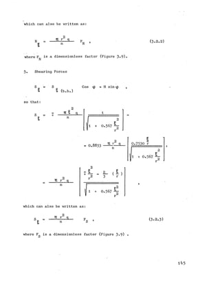
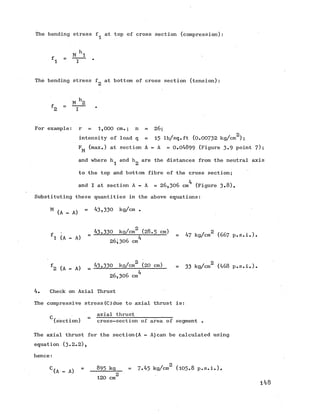
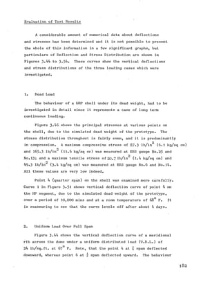
This thesis investigates the use of glass fibre reinforced plastics (GRP) as a structural material, focusing on its feasibility, cost-effective molding techniques, and the performance of hyperbolic paraboloidal shells. A special 'cocooning' molding technique was developed to facilitate the manufacture of GRP elements, overcoming high mold costs, and extensive experiments were conducted using a large model with various loading tests. The research concludes that GRP can effectively compete with conventional materials in construction through innovative designs and applications.
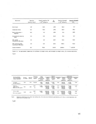
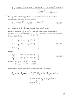
![stress-lb/sq.in(kg/sq.cm)stress-Ib/sq.in(kg/sq.cm)
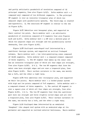
213,000
(15,000)
3,520
(600]
7,100
(500)
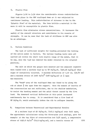
142,000
(10,0 0 0 )
5,680
(400)
£ 4,260
H (300)
cr
in
cn
JSC
'T ' 2,840
.E (200)
cr
(/i
JQ
. 1.420
U) (100)
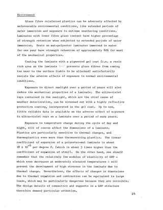
U)
o
p o ly e s te r r<?sinsass fib 0|i dig.71,000
(5,000)
2 30 4 0 2-00-5 1-51-0
s t r a i n % s t r a i n 0/#
85,200
(6,000)
G R P - r o v i n g
71,000
(5,000)
56,800
(4,000)
GRP- clo th42,600
(3,000)
u G R P - c h o p p e d s t r a n d s
14,200
(1,000)
0 2 3 4
s t r a i n %
1.4](https://image.slidesharecdn.com/hyperboloidconstruction-191120105516/85/Hyperboloid-construction-29-320.jpg)
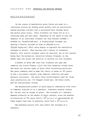
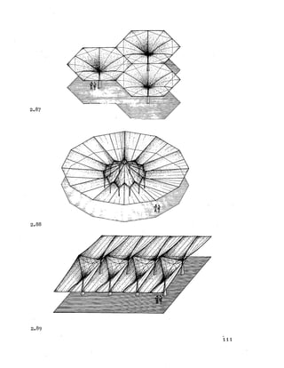
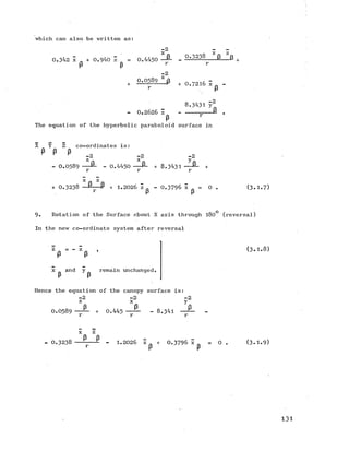
![m a c ro -m o d u la r unit
a x is of re v o lu tio n
paralle]s_____
g e n e ra trix =
m e rid ia n
2.l6 2.17
m ic ro -m o d u la r u n it
infra-m oduiar unit
H
axis of revolution
meridian
2.18 2.19
'50](https://image.slidesharecdn.com/hyperboloidconstruction-191120105516/85/Hyperboloid-construction-51-320.jpg)
![2E
z — cos2 § [o.5 0 3 6 - 8.3434 (0 .119862)] ,
2
I
= 0.377 ■ — .
Note that the space curve CO is a parabola with a lower rise than
the principal parabola (l) (Figure 3-4 ).
5. Check:
If g = r, then the above equation becomes simply
z = 0.377 r .
By inspection
Thus:
z = 0.4969 r - 0.1199 r = 0.377 r .
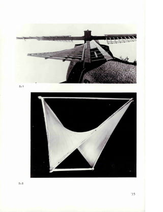
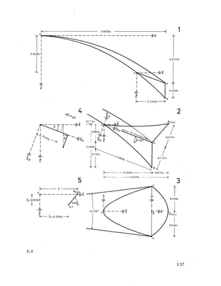
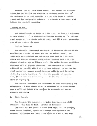
The Hyperbolic Paraboloid Canopy
1. Delimitation of Curve AFC
Let J3 =20^ be the angle between the intersecting plane AFC and
the XYplane (Figure 3-5 (2).) the projection of the curveAFC, on
the ZX plane, is a straight line, hence:
z = x tan p + (f^ - *2 ^ “ a tan 3 ’
which can also be written as:
z = (f^ - f ) - (a - x) tan p . (3 .1.2 )
126](https://image.slidesharecdn.com/hyperboloidconstruction-191120105516/85/Hyperboloid-construction-127-320.jpg)
![Substituting equation (3.1.2) in (3-1) gives the general formula
for the curve AFC in its horizontal projection on the XY plane,
■which reads:
(fa - f2) - (a - x) tan p “ ■ fi % “
2 b2
(3.1.3)
Substituting numerical values:
0 .3 7 6 5 r - (0 .9 9 2 8 r - x) tan p = - (0 .5 0 3 6 x2 - 8.3431 y2) .
2. Location of the Point F.
At point F on the curve AFC, y = 0. Thus substituting the value of y
into equation (3 .1.3 ) gives:
0 .3 7 6 5 r - 0 .9 9 2 8 r tanp + x tan p = ^ 0 .5 3 6 x2 ,
which can also be written as:
0 .5 0 3 6 x2 - 0.3640 x r = [0.3765 « 0 .9 9 2 8 (0.3640)] r2
Solving for x:
2 0.3640
x - —— r x =
0 .5 0 3 6
0.3765 - 0 .9 9 2 8 (0.3640)
0.5036
x2 - 0 .7 2 2 8 r x = 0.030024 r2 ,
= 0.3614 r + j 0 .1 3 0 6 + 0.030024 r ,
= (0.3614 ± 0.4007) r ,
= 0 .7 6 2 2 r.
3. Calculation of the z Ordinate of the Point F.
127](https://image.slidesharecdn.com/hyperboloidconstruction-191120105516/85/Hyperboloid-construction-128-320.jpg)
![Substituting for x_ in the general equation (3.1.2):
F
z = 0 .3 7 6 5 r - [0 .9 9 2 8 (0.3640)] r + 0.364 x ,
= 0.0151 r + 0.364 x ,
Zp = 0.0151 r + [0.364 (0.7622 r )] ,
= 0.2925 r .
4. Locus of the Space Curve AFC.
To calculate the locus of the curve AFC in its horizontal projection
on the XY plane, equation (3.1.3) is used.
Substituting numerical values:
0.3765 r2 - [0 .9 9 2 8 (0.364 r2) ] + 0.364 m r2
= 0.5036 m2 r2 - 8.341 y2
(where m = x/r a dimensionless quantity)
Solving for y ;
2 1
0 .5 0 3 6 m2 - 0.364 m - [0 .3 7 6 5 - 0 .9 9 2 8 (0.364)]y
8 .3 4 3 1
y
2
0.364 m - 0 .01512)
With this equation the projection of the curve AFC on the XY plane can
be plotted as shown in Figure 3-6 .
5. The z Ordinates of the Space-Curve AFC.
Having found the XY co-ordinates for the space curve AFC its z
ordinates can be calculated by using equation (3-1.2) .](https://image.slidesharecdn.com/hyperboloidconstruction-191120105516/85/Hyperboloid-construction-129-320.jpg)
![Substituting numerical values:
z = O .3765 r - [0 .9 9 2 8 (0.3640)] r + m 0.3640 .
With this equation the curve AFC projected on the ZY plane can be
plotted as shown in Figure 3*6 . •
6. Equation of the Canopy Surface.
Three operations are necessary in order to obtain the surface equation
of the projected canopy (Figure 3*5). 1. Translation along the X axis.
2. Rotation about the Y axis through 20^. 3- Rotation about the
X axis through 180^ (reversal) .
7. Translation of Co-ordinate System X,Y,Z.
The point F is taken as the new origin of co-ordinates.
Translating the original co-ordinate system (X,Y,Z) to the new
co-ordinate system (X,Y,Z) with its origin at point F gives:
z = z ,
F ’
X X
(3-1.4)
y y
Thus:
z z + z.
F
X X + X.
F
Since x = O .7622 r, and z = 0.2926 r .
r r
Substituting these quantities in equation (3.1.2) gives:
z + 0 .2 9 2 6 r = ~ [x + 0 .7 6 2 2 r2 ( 0.5036) - 8.341 y2 ] ,
129](https://image.slidesharecdn.com/hyperboloidconstruction-191120105516/85/Hyperboloid-construction-130-320.jpg)
![10. Location of Point B (reversal)
To find the point B (rev.) on the tilted parabolic free edge
as shown in Figures 3-3 and 3-5(2) in X,Y,Z co-ordinates requires
the following three steps.
(1) Translation:
B = ° ’
x = 0 .2 3 0 6 r .
B
Substituting these quantities in equation (3-1-5)
zB = [0 .5 0 3 6 (0 .23062) + 0.7677 (0 .2306)] r,
= (0 .0 2 6 8 + 0 .1770) r ,
0 .2 0 3 8 r .
(2) Rotation 20°:
Using equation(3.1.6.l)
£ = 0 .2 3 0 6 (0.946) r + 0 .2 0 3 8 (0.342) r ,
p B
= (0 .2 1 6 8 + 0 .0700) r ,
= 0 .2 8 6 8 r .
z = - 0 .2 3 0 6 (0.342) r + 0 .2 0 3 8 (0.940) r ,
P B
= (-O.O789 + 0 .1916) r ,
= 0.1127 r .
1 3 2](https://image.slidesharecdn.com/hyperboloidconstruction-191120105516/85/Hyperboloid-construction-133-320.jpg)
![(3) Rotation 180°:
For the point B (rev.)
x = 0.2865 r ,
z = - 0.1127 r .
P
Substituting these values in equation (3.1.6):
xD = [0 .2 8 6 5 (0.940) +0.1127 (0.342) 1 r ,
B ■*
= (0.2693 + 0.03854) r ,
0.30784 r .
z = [0 .2 8 6 5 (0.342)-(0.1127) 0.940 ] r ,
B 1 J
= ( 0.09798 - 0.1059 ) r ,
= -0 .0 0 7 9 6 r .
11. The Free Edge Curve A B (rev.) C
Similarly, to determine the equation of the tiltedparabolic free
edge in X ^ Z ^co-ordinates requires the following three steps.
(1) Translation:
Using equation (3.1.1) and substituting x =a = 0.9928 r;
z = [ 0 .5 0 3 6 (0 .99282) r2 - 8.3431 y2 ] ,
2
= - 8.341 ^ + 0.4964 r .](https://image.slidesharecdn.com/hyperboloidconstruction-191120105516/85/Hyperboloid-construction-134-320.jpg)
![■ z [ 0.940 - 0.364 (0.342)] = X [0 .3 4 2 + 0.364 (0.940)] .+
2
+ 8 .8 7 5 6 ~ - 0 .2 1 6 8 r ,
2
z (0.8155) = x (0.684) + 8 .8 7 5 6 - - 0 .2 1 6 8 r ,
r
2
z ■= x 0.83875+ 10.8836^ - 0 .2 6 5 8 r . (3.1.11)
If x 0.30784 r ,
z = 0 .2 5 8 2 r - 0 .2 6 5 8 r = - 0 .0 0 7 6 r ,
which corresponds closely enough to the previously calculated
z = - 0 .0 0 7 9 6 r .
13. Equation of the Space Curve AB (rev) C Projected on the XY Plane.
The vertical projection of the space curve AB (rev) C gives a straight
line which passes through the points AC - B (rev) as shown in
Figure 3.5.(5) •
(z - z^) = tany (x - x^) . (3.1.12)
Since
y = - 50° tan Y (-50°) = - 1.1918 ,
= + 0.0839 r ,
x^ = 0.2306 r .
Hence
z = - 1.1918 x + 1.1918 (0.2306)r + 0.0839 r. (3 .1.13)
Using equation (3.1.11) and (3-1.13) one unknown can be eliminated
135](https://image.slidesharecdn.com/hyperboloidconstruction-191120105516/85/Hyperboloid-construction-136-320.jpg)
![In order to simulate the stress condition in the prototype, the
dead weight of the model must first be subtracted from the dead
weight of the prototype.
The dead weight of the prototype is:
p 2 2
4.2 kg/m (5 ) = 21 kg/ m (4.3 lb/ft. ) and subtracting from
it the dead weight of the model this gives:
2 2 2
21 kg/m - 4.2 kg/m = 16 .8 kg/m which multiplied by the
area of the model then gives:
[l6.8 kg/m^ (0.48 m^ )]2 6 = 211 kg.
Having 1,248 loading points on the dome (not considering the 104 points
on the small cantilevering portion of the canopies), the resulting
load on each point is:
211 kg _ _
17548 " °-169 k9‘
Since each loading hook is connected to four points, the load per
hook on the model which will simulate the dead weight of the prototype
will have to be:
0.169 kg (4) = O .6 7 8 kg.
2. Snow Load
The requirements of British Standard Code of Practice 3* Ch.5
for roofs of limited access, allow for 2 ft. of snow, 15 lb/sq.ft.
(73.24 kg/sq .m.) on plan. That is to say, auniform load per unit
area of horizontal shell projection. A minimum additional factor of
safety of 1.5 was agreed upon with the local District Surveyor for
the town where the prototype is to be erected and the design loading
thus works out to be 22^ lb/sq.ft (110 kg/sq.m.). (This factor of
safety is in addition to the normal factor of safety used in
the design).
To simulate the stress condition as in the prototype, due to the
maximum required snow load, the model required the application of a
load intensity of 110 kg/sq.m. Since the area of the model was .
12.57 sq.m., the total load on the model was 1,3^3 kg., distributed
1 7 4](https://image.slidesharecdn.com/hyperboloidconstruction-191120105516/85/Hyperboloid-construction-175-320.jpg)
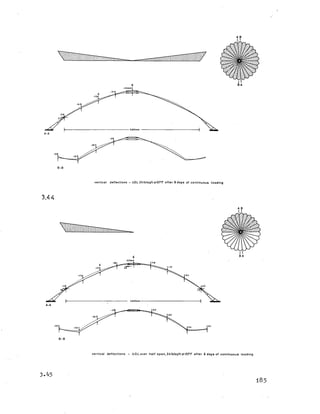
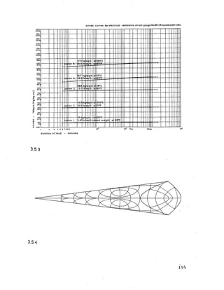
![d eflectio n curves for p o in t4 (q u a rte r span) under UD.L.
24.0
91.7
ve 4
66.8
13.7
18*C
I 0300
.5 (7.62]
ma>
■C
u
C 0200
,21.5‘ C
71*F8.6
i
in
c
o
20’C
ad we
17 kg/sq.ti
3.471b. ’sq.ft. ght
1Day 6 Days
duration of load - minutes
3.51
strain curves for electrical resistance strain gaugeNo.25( 1/6 span)underU.D.L.
(0.27.) 2,000
67*F
(0.17.) 1,000
63’ F
41.! kc /s 21.5'C
ght
ID ay 6Days
duration of load minutes
3-52
193](https://image.slidesharecdn.com/hyperboloidconstruction-191120105516/85/Hyperboloid-construction-194-320.jpg)


![11.[1 10]shear strength study of rc beams retrofitted using vinyl ester bonded](https://cdn.slidesharecdn.com/ss_thumbnails/11-1-10shearstrengthstudyofrcbeamsretrofittedusingvinylesterbonded-120512235418-phpapp02-thumbnail.jpg?width=640&height=640&fit=bounds)
![11.[1 10]shear strength study of rc beams retrofitted using vinyl ester bonded](https://cdn.slidesharecdn.com/ss_thumbnails/11-1-10shearstrengthstudyofrcbeamsretrofittedusingvinylesterbonded-120512235346-phpapp02-thumbnail.jpg?width=640&height=640&fit=bounds)


