Download to read offline
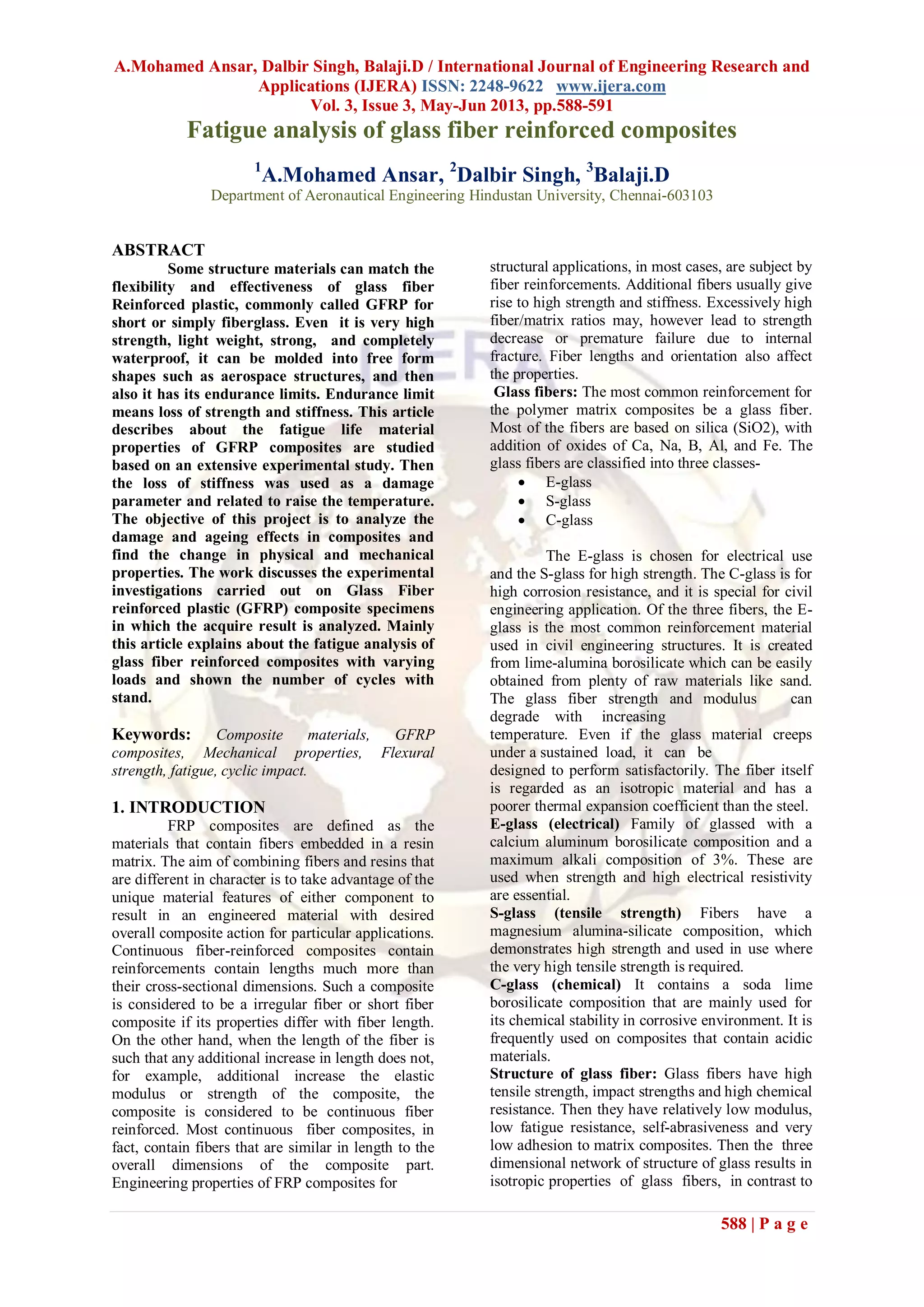
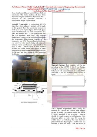

This document discusses a study on the fatigue analysis of glass fiber reinforced composites. It describes how glass fiber reinforced epoxy laminate composite samples were manufactured using vacuum bagging technique. The samples were then cut and tested under varying cyclic loads on a fatigue testing machine. The results showed that the glass fiber reinforced composites could withstand fatigue loads efficiently compared to aluminum and the number of cycles before failure decreased as the applied load increased. The document concludes that future work could extend these tests under different loading conditions to improve stress variation understanding and enable application in aircraft structures.


![Getting Started with Apache Spark: Big Data Made Simple [Free Meetup]](https://cdn.slidesharecdn.com/ss_thumbnails/apachesparkgettingstarted-260203175547-8361bcc3-thumbnail.jpg?width=640&height=640&fit=bounds)


