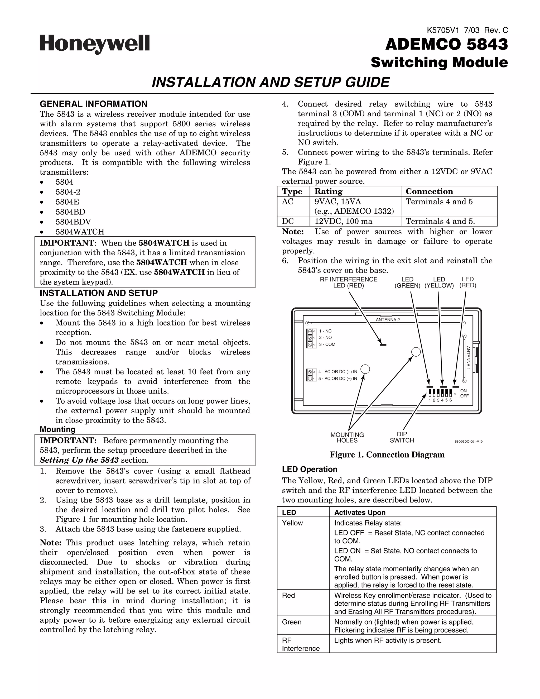
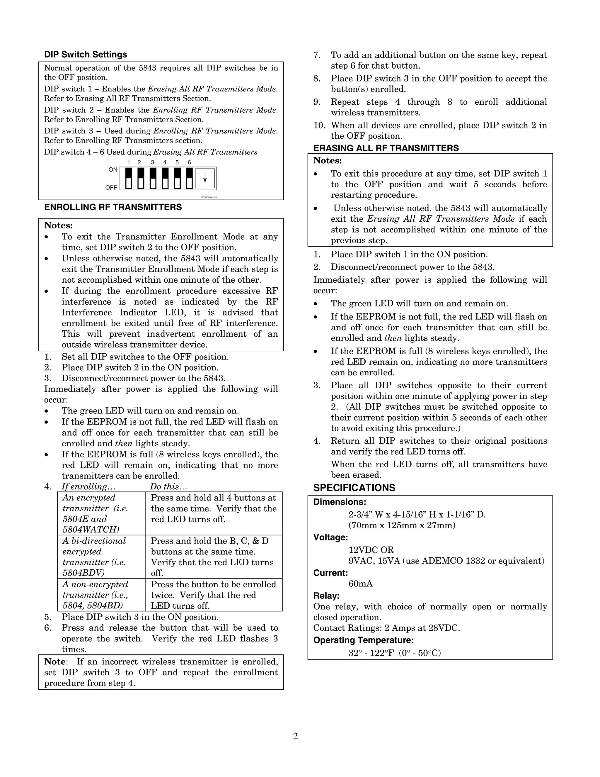
K5705V1 7/03 Rev. C

                                                                                                   ADEMCO 5843
                                                         Switching Module
                               INSTALLATION AND SETUP GUIDE
GENERAL INFORMATION                                            4.  Connect desired relay switching wire to 5843
The 5843 is a wireless receiver module intended for use            terminal 3 (COM) and terminal 1 (NC) or 2 (NO) as
with alarm systems that support 5800 series wireless               required by the relay. Refer to relay manufacturer’s
devices. The 5843 enables the use of up to eight wireless          instructions to determine if it operates with a NC or
transmitters to operate a relay-activated device. The              NO switch.
5843 may only be used with other ADEMCO security               5. Connect power wiring to the 5843’s terminals. Refer
products. It is compatible with the following wireless             Figure 1.
transmitters:                                                  The 5843 can be powered from either a 12VDC or 9VAC
•   5804                                                       external power source.
•   5804-2                                                     Type     Rating                   Connection
•   5804E                                                      AC       9VAC, 15VA               Terminals 4 and 5
•   5804BD                                                              (e.g., ADEMCO 1332)
•   5804BDV                                                    DC       12VDC, 100 ma            Terminals 4 and 5.
•   5804WATCH                                                  Note: Use of power sources with higher or lower
IMPORTANT: When the 5804WATCH is used in                       voltages may result in damage or failure to operate
conjunction with the 5843, it has a limited transmission       properly.
range. Therefore, use the 5804WATCH when in close              6. Position the wiring in the exit slot and reinstall the
proximity to the 5843 (EX. use 5804WATCH in lieu of                5843’s cover on the base.
                                                                              RF INTERFERENCE            LED      LED    LED
the system keypad).                                                               LED (RED)            (GREEN) (YELLOW) (RED)
INSTALLATION AND SETUP
Use the following guidelines when selecting a mounting
location for the 5843 Switching Module:
                                                                                                ANTENNA 2
•   Mount the 5843 in a high location for best wireless
    reception.                                                            1 - NC
                                                                          2 - NO
•   Do not mount the 5843 on or near metal objects.                       3 - COM


                                                                                                                                   ANTENNA 1
    This decreases range and/or blocks wireless
    transmissions.
•   The 5843 must be located at least 10 feet from any                    4 - AC OR DC (+) IN
                                                                          5 - AC OR DC ( ) IN
    remote keypads to avoid interference from the
    microprocessors in those units.                                                                                             ON
                                                                                                                                OFF
•   To avoid voltage loss that occurs on long power lines,                                                      1 2 3 4 5 6

    the external power supply unit should be mounted
    in close proximity to the 5843.
Mounting
                                                                                MOUNTING              DIP
IMPORTANT: Before permanently mounting the                                       HOLES               SWITCH                   5800GDO-001-V10


5843, perform the setup procedure described in the
                                                                                Figure 1. Connection Diagram
Setting Up the 5843 section.
1. Remove the 5843's cover (using a small flathead             LED Operation
    screwdriver, insert screwdriver’s tip in slot at top of    The Yellow, Red, and Green LEDs located above the DIP
    cover to remove).                                          switch and the RF interference LED located between the
2. Using the 5843 base as a drill template, position in        two mounting holes, are described below.
    the desired location and drill two pilot holes. See        LED                 Activates Upon
    Figure 1 for mounting hole location.                       Yellow              Indicates Relay state:
3. Attach the 5843 base using the fasteners supplied.                              LED OFF = Reset State, NC contact connected
Note: This product uses latching relays, which retain                              to COM.
their open/closed position even when power is                                      LED ON = Set State, NO contact connects to
disconnected. Due to shocks or vibration during                                    COM.
shipment and installation, the out-of-box state of these                           The relay state momentarily changes when an
                                                                                   enrolled button is pressed. When power is
relays may be either open or closed. When power is first                           applied, the relay is forced to the reset state.
applied, the relay will be set to its correct initial state.
                                                               Red                 Wireless Key enrollment/erase indicator. (Used to
Please bear this in mind during installation; it is                                determine status during Enrolling RF Transmitters
strongly recommended that you wire this module and                                 and Erasing All RF Transmitters procedures).
apply power to it before energizing any external circuit       Green               Normally on (lighted) when power is applied.
controlled by the latching relay.                                                  Flickering indicates RF is being processed.
                                                               RF                  Lights when RF activity is present.
                                                               Interference
DIP Switch Settings                                                7.  To add an additional button on the same key, repeat
Normal operation of the 5843 requires all DIP switches be in           step 6 for that button.
the OFF position.                                                  8. Place DIP switch 3 in the OFF position to accept the
DIP switch 1 – Enables the Erasing All RF Transmitters Mode.           button(s) enrolled.
Refer to Erasing All RF Transmitters Section.                      9. Repeat steps 4 through 8 to enroll additional
DIP switch 2 – Enables the Enrolling RF Transmitters Mode.             wireless transmitters.
Refer to Enrolling RF Transmitters Section.
                                                                   10. When all devices are enrolled, place DIP switch 2 in
DIP switch 3 – Used during Enrolling RF Transmitters Mode.
Refer to Enrolling RF Transmitters section.
                                                                       the OFF position.
DIP switch 4 – 6 Used during Erasing All RF Transmitters           ERASING ALL RF TRANSMITTERS
                      1   2   3   4   5   6                        Notes:
                ON
                                                                   •   To exit this procedure at any time, set DIP switch 1
               OFF                                                     to the OFF position and wait 5 seconds before
                                              5800GDO-002-V0           restarting procedure.
ENROLLING RF TRANSMITTERS                                          •    Unless otherwise noted, the 5843 will automatically
                                                                       exit the Erasing All RF Transmitters Mode if each
Notes:                                                                 step is not accomplished within one minute of the
•   To exit the Transmitter Enrollment Mode at any                     previous step.
    time, set DIP switch 2 to the OFF position.
•   Unless otherwise noted, the 5843 will automatically            1. Place DIP switch 1 in the ON position.
    exit the Transmitter Enrollment Mode if each step is           2. Disconnect/reconnect power to the 5843.
    not accomplished within one minute of the other.               Immediately after power is applied the following will
•   If during the enrollment procedure excessive RF                occur:
    interference is noted as indicated by the RF                   •   The green LED will turn on and remain on.
    Interference Indicator LED, it is advised that                 •   If the EEPROM is not full, the red LED will flash on
    enrollment be exited until free of RF interference.                and off once for each transmitter that can still be
    This will prevent inadvertent enrollment of an                     enrolled and then lights steady.
    outside wireless transmitter device.
                                                                   •   If the EEPROM is full (8 wireless keys enrolled), the
1. Set all DIP switches to the OFF position.
                                                                       red LED remain on, indicating no more transmitters
2. Place DIP switch 2 in the ON position.
                                                                       can be enrolled.
3. Disconnect/reconnect power to the 5843.
Immediately after power is applied the following will              3. Place all DIP switches opposite to their current
occur:                                                                 position within one minute of applying power in step
•   The green LED will turn on and remain on.                          2. (All DIP switches must be switched opposite to
•   If the EEPROM is not full, the red LED will flash on               their current position within 5 seconds of each other
                                                                       to avoid exiting this procedure.)
    and off once for each transmitter that can still be
    enrolled and then lights steady.                               4. Return all DIP switches to their original positions
•   If the EEPROM is full (8 wireless keys enrolled), the              and verify the red LED turns off.
    red LED will remain on, indicating that no more                    When the red LED turns off, all transmitters have
    transmitters can be enrolled.                                      been erased.
4. If enrolling…          Do this…                                 SPECIFICATIONS
    An encrypted          Press and hold all 4 buttons at          Dimensions:
    transmitter (i.e.     the same time. Verify that the
                                                                            2-3/4” W x 4-15/16” H x 1-1/16” D.
    5804E and             red LED turns off.
    5804WATCH)                                                              (70mm x 125mm x 27mm)
    A bi-directional      Press and hold the B, C, & D             Voltage:
    encrypted             buttons at the same time.                         12VDC OR
    transmitter (i.e.     Verify that the red LED turns                     9VAC, 15VA (use ADEMCO 1332 or equivalent)
    5804BDV)              off.                                     Current:
    A non-encrypted       Press the button to be enrolled                   60mA
    transmitter (i.e.,    twice. Verify that the red               Relay:
    5804, 5804BD)         LED turns off.                           One relay, with choice of normally open or normally
5. Place DIP switch 3 in the ON position.                          closed operation.
6. Press and release the button that will be used to               Contact Ratings: 2 Amps at 28VDC.
    operate the switch. Verify the red LED flashes 3               Operating Temperature:
    times.                                                                  32° - 122°F (0° - 50°C)
Note: If an incorrect wireless transmitter is enrolled,
set DIP switch 3 to OFF and repeat the enrollment
procedure from step 4.


                                                               2
Federal Communications Commission (FCC) Part 15
The user shall not make any changes or modifications to the equipment unless authorized by the Installation Instructions or User's Manual.
Unauthorized changes or modifications could void the user's authority to operate the equipment.
CLASS B DIGITAL DEVICE STATEMENT
NOTE: This equipment has been tested and found to comply with the limits for a Class B digital device, pursuant to part 15 of the FCC Rules. These
limits are designed to provide reasonable protection against harmful interference in a residential installation. This equipment generates, uses and can
radiate radio frequency energy and, if not installed and used in accordance with the instructions, may cause harmful interference to radio
communications. However, there is no guarantee that interference will not occur in a particular installation. If this equipment does cause harmful
interference to radio or television reception, which can be determined by turning the equipment off and on, the user is encouraged to try to correct the
interference by one or more of the following measures:
•    Reorient or relocate the receiving antenna.
•    Increase the separation between the equipment and receiver.
•    Connect the equipment into an outlet on a circuit different from that to which the receiver is connected.
•    Consult the dealer or an experienced radio/TV technician for help.
This Class B digital apparatus complies with Canadian ICES-003.
Cet appareil numérique de la classe B est conforme à la norme NMB-003 du Canada.
FCC/IC STATEMENT
This device complies with Part 15 of the FCC rules and RSS 210 of Industry Canada. Operation is subject to the following two conditions: (1) This
device may not cause harmful interference, and (2) This device must accept any interference received, including interference that may cause
undesired operation.
Cet appareil est conforme à la partie 15 des règles de la FCC & de RSS 210 des Industries Canada. Son fonctionnement est soumis aux conditions
suivantes: (1) Cet appareil ne doit pas causer d' interferences nuisibles. (2) Cet appareil doit accepter toute interference reçue y compris les
interferences causant une reception indésirable.


                                                                            3
For the latest warranty information, please go to:
                       http://www.security.honeywell.com/hsc/resources/wa/index.html


                      2 Corporate Center Drive, Melville, NY 11747
                           Copyright © 2007 Honeywell International Inc.

                                      www.honeywell.com/security


ÊK5705V1NŠ
K5705V1 7/03 Rev. C

Honeywell 5843-install-guide

  • 1.
    K5705V1 7/03 Rev.C ADEMCO 5843 Switching Module INSTALLATION AND SETUP GUIDE GENERAL INFORMATION 4. Connect desired relay switching wire to 5843 The 5843 is a wireless receiver module intended for use terminal 3 (COM) and terminal 1 (NC) or 2 (NO) as with alarm systems that support 5800 series wireless required by the relay. Refer to relay manufacturer’s devices. The 5843 enables the use of up to eight wireless instructions to determine if it operates with a NC or transmitters to operate a relay-activated device. The NO switch. 5843 may only be used with other ADEMCO security 5. Connect power wiring to the 5843’s terminals. Refer products. It is compatible with the following wireless Figure 1. transmitters: The 5843 can be powered from either a 12VDC or 9VAC • 5804 external power source. • 5804-2 Type Rating Connection • 5804E AC 9VAC, 15VA Terminals 4 and 5 • 5804BD (e.g., ADEMCO 1332) • 5804BDV DC 12VDC, 100 ma Terminals 4 and 5. • 5804WATCH Note: Use of power sources with higher or lower IMPORTANT: When the 5804WATCH is used in voltages may result in damage or failure to operate conjunction with the 5843, it has a limited transmission properly. range. Therefore, use the 5804WATCH when in close 6. Position the wiring in the exit slot and reinstall the proximity to the 5843 (EX. use 5804WATCH in lieu of 5843’s cover on the base. RF INTERFERENCE LED LED LED the system keypad). LED (RED) (GREEN) (YELLOW) (RED) INSTALLATION AND SETUP Use the following guidelines when selecting a mounting location for the 5843 Switching Module: ANTENNA 2 • Mount the 5843 in a high location for best wireless reception. 1 - NC 2 - NO • Do not mount the 5843 on or near metal objects. 3 - COM ANTENNA 1 This decreases range and/or blocks wireless transmissions. • The 5843 must be located at least 10 feet from any 4 - AC OR DC (+) IN 5 - AC OR DC ( ) IN remote keypads to avoid interference from the microprocessors in those units. ON OFF • To avoid voltage loss that occurs on long power lines, 1 2 3 4 5 6 the external power supply unit should be mounted in close proximity to the 5843. Mounting MOUNTING DIP IMPORTANT: Before permanently mounting the HOLES SWITCH 5800GDO-001-V10 5843, perform the setup procedure described in the Figure 1. Connection Diagram Setting Up the 5843 section. 1. Remove the 5843's cover (using a small flathead LED Operation screwdriver, insert screwdriver’s tip in slot at top of The Yellow, Red, and Green LEDs located above the DIP cover to remove). switch and the RF interference LED located between the 2. Using the 5843 base as a drill template, position in two mounting holes, are described below. the desired location and drill two pilot holes. See LED Activates Upon Figure 1 for mounting hole location. Yellow Indicates Relay state: 3. Attach the 5843 base using the fasteners supplied. LED OFF = Reset State, NC contact connected Note: This product uses latching relays, which retain to COM. their open/closed position even when power is LED ON = Set State, NO contact connects to disconnected. Due to shocks or vibration during COM. shipment and installation, the out-of-box state of these The relay state momentarily changes when an enrolled button is pressed. When power is relays may be either open or closed. When power is first applied, the relay is forced to the reset state. applied, the relay will be set to its correct initial state. Red Wireless Key enrollment/erase indicator. (Used to Please bear this in mind during installation; it is determine status during Enrolling RF Transmitters strongly recommended that you wire this module and and Erasing All RF Transmitters procedures). apply power to it before energizing any external circuit Green Normally on (lighted) when power is applied. controlled by the latching relay. Flickering indicates RF is being processed. RF Lights when RF activity is present. Interference
  • 2.
    DIP Switch Settings 7. To add an additional button on the same key, repeat Normal operation of the 5843 requires all DIP switches be in step 6 for that button. the OFF position. 8. Place DIP switch 3 in the OFF position to accept the DIP switch 1 – Enables the Erasing All RF Transmitters Mode. button(s) enrolled. Refer to Erasing All RF Transmitters Section. 9. Repeat steps 4 through 8 to enroll additional DIP switch 2 – Enables the Enrolling RF Transmitters Mode. wireless transmitters. Refer to Enrolling RF Transmitters Section. 10. When all devices are enrolled, place DIP switch 2 in DIP switch 3 – Used during Enrolling RF Transmitters Mode. Refer to Enrolling RF Transmitters section. the OFF position. DIP switch 4 – 6 Used during Erasing All RF Transmitters ERASING ALL RF TRANSMITTERS 1 2 3 4 5 6 Notes: ON • To exit this procedure at any time, set DIP switch 1 OFF to the OFF position and wait 5 seconds before 5800GDO-002-V0 restarting procedure. ENROLLING RF TRANSMITTERS • Unless otherwise noted, the 5843 will automatically exit the Erasing All RF Transmitters Mode if each Notes: step is not accomplished within one minute of the • To exit the Transmitter Enrollment Mode at any previous step. time, set DIP switch 2 to the OFF position. • Unless otherwise noted, the 5843 will automatically 1. Place DIP switch 1 in the ON position. exit the Transmitter Enrollment Mode if each step is 2. Disconnect/reconnect power to the 5843. not accomplished within one minute of the other. Immediately after power is applied the following will • If during the enrollment procedure excessive RF occur: interference is noted as indicated by the RF • The green LED will turn on and remain on. Interference Indicator LED, it is advised that • If the EEPROM is not full, the red LED will flash on enrollment be exited until free of RF interference. and off once for each transmitter that can still be This will prevent inadvertent enrollment of an enrolled and then lights steady. outside wireless transmitter device. • If the EEPROM is full (8 wireless keys enrolled), the 1. Set all DIP switches to the OFF position. red LED remain on, indicating no more transmitters 2. Place DIP switch 2 in the ON position. can be enrolled. 3. Disconnect/reconnect power to the 5843. Immediately after power is applied the following will 3. Place all DIP switches opposite to their current occur: position within one minute of applying power in step • The green LED will turn on and remain on. 2. (All DIP switches must be switched opposite to • If the EEPROM is not full, the red LED will flash on their current position within 5 seconds of each other to avoid exiting this procedure.) and off once for each transmitter that can still be enrolled and then lights steady. 4. Return all DIP switches to their original positions • If the EEPROM is full (8 wireless keys enrolled), the and verify the red LED turns off. red LED will remain on, indicating that no more When the red LED turns off, all transmitters have transmitters can be enrolled. been erased. 4. If enrolling… Do this… SPECIFICATIONS An encrypted Press and hold all 4 buttons at Dimensions: transmitter (i.e. the same time. Verify that the 2-3/4” W x 4-15/16” H x 1-1/16” D. 5804E and red LED turns off. 5804WATCH) (70mm x 125mm x 27mm) A bi-directional Press and hold the B, C, & D Voltage: encrypted buttons at the same time. 12VDC OR transmitter (i.e. Verify that the red LED turns 9VAC, 15VA (use ADEMCO 1332 or equivalent) 5804BDV) off. Current: A non-encrypted Press the button to be enrolled 60mA transmitter (i.e., twice. Verify that the red Relay: 5804, 5804BD) LED turns off. One relay, with choice of normally open or normally 5. Place DIP switch 3 in the ON position. closed operation. 6. Press and release the button that will be used to Contact Ratings: 2 Amps at 28VDC. operate the switch. Verify the red LED flashes 3 Operating Temperature: times. 32° - 122°F (0° - 50°C) Note: If an incorrect wireless transmitter is enrolled, set DIP switch 3 to OFF and repeat the enrollment procedure from step 4. 2
  • 3.
    Federal Communications Commission(FCC) Part 15 The user shall not make any changes or modifications to the equipment unless authorized by the Installation Instructions or User's Manual. Unauthorized changes or modifications could void the user's authority to operate the equipment. CLASS B DIGITAL DEVICE STATEMENT NOTE: This equipment has been tested and found to comply with the limits for a Class B digital device, pursuant to part 15 of the FCC Rules. These limits are designed to provide reasonable protection against harmful interference in a residential installation. This equipment generates, uses and can radiate radio frequency energy and, if not installed and used in accordance with the instructions, may cause harmful interference to radio communications. However, there is no guarantee that interference will not occur in a particular installation. If this equipment does cause harmful interference to radio or television reception, which can be determined by turning the equipment off and on, the user is encouraged to try to correct the interference by one or more of the following measures: • Reorient or relocate the receiving antenna. • Increase the separation between the equipment and receiver. • Connect the equipment into an outlet on a circuit different from that to which the receiver is connected. • Consult the dealer or an experienced radio/TV technician for help. This Class B digital apparatus complies with Canadian ICES-003. Cet appareil numérique de la classe B est conforme à la norme NMB-003 du Canada. FCC/IC STATEMENT This device complies with Part 15 of the FCC rules and RSS 210 of Industry Canada. Operation is subject to the following two conditions: (1) This device may not cause harmful interference, and (2) This device must accept any interference received, including interference that may cause undesired operation. Cet appareil est conforme à la partie 15 des règles de la FCC & de RSS 210 des Industries Canada. Son fonctionnement est soumis aux conditions suivantes: (1) Cet appareil ne doit pas causer d' interferences nuisibles. (2) Cet appareil doit accepter toute interference reçue y compris les interferences causant une reception indésirable. 3
  • 4.
    For the latestwarranty information, please go to: http://www.security.honeywell.com/hsc/resources/wa/index.html 2 Corporate Center Drive, Melville, NY 11747 Copyright © 2007 Honeywell International Inc. www.honeywell.com/security ÊK5705V1NŠ K5705V1 7/03 Rev. C