The document provides an overview and user manual for the HF2211 Serial Server Device. It includes:
1. An overview of the device's characteristics including its MCU, memory, protocols supported, interfaces, security features, and dimensions.
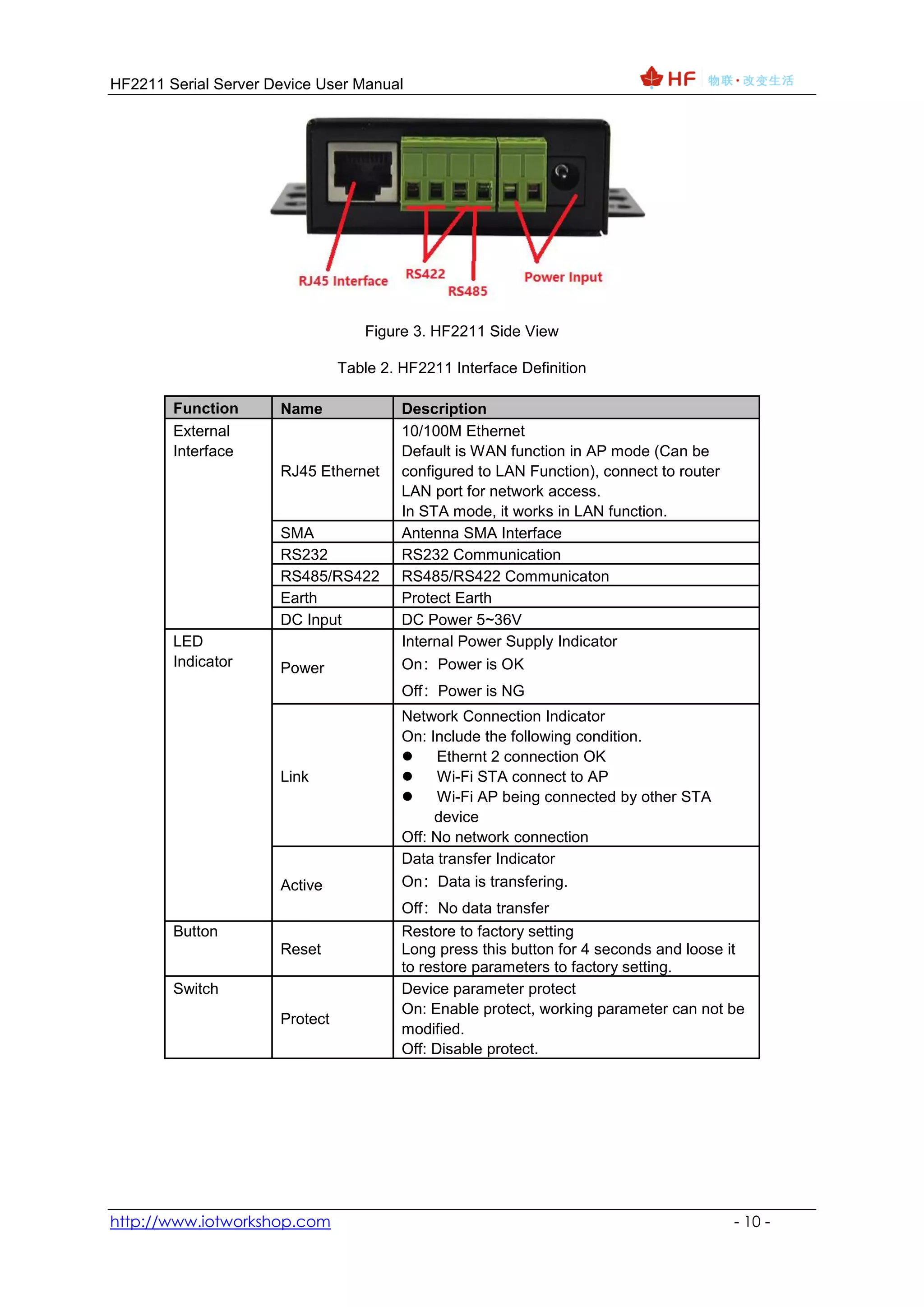
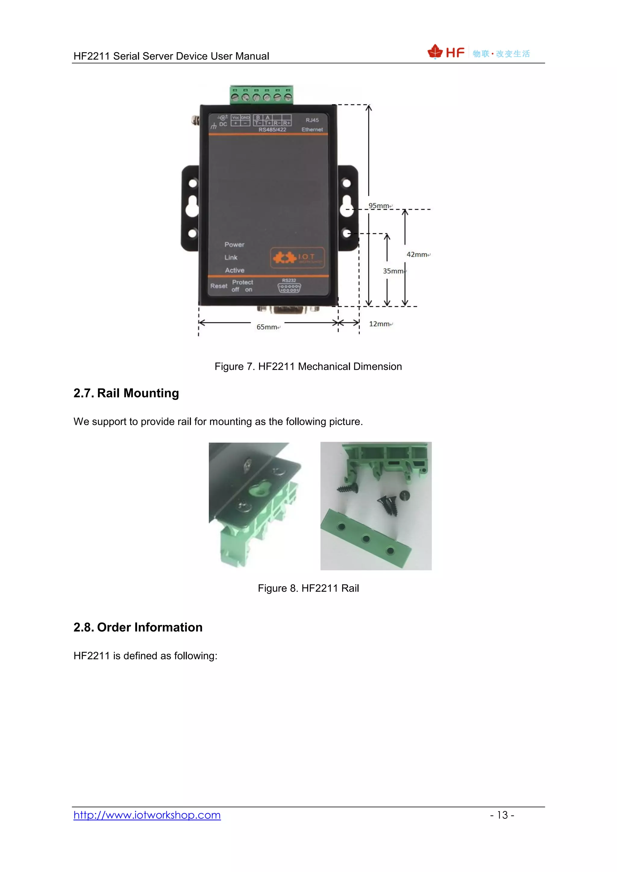
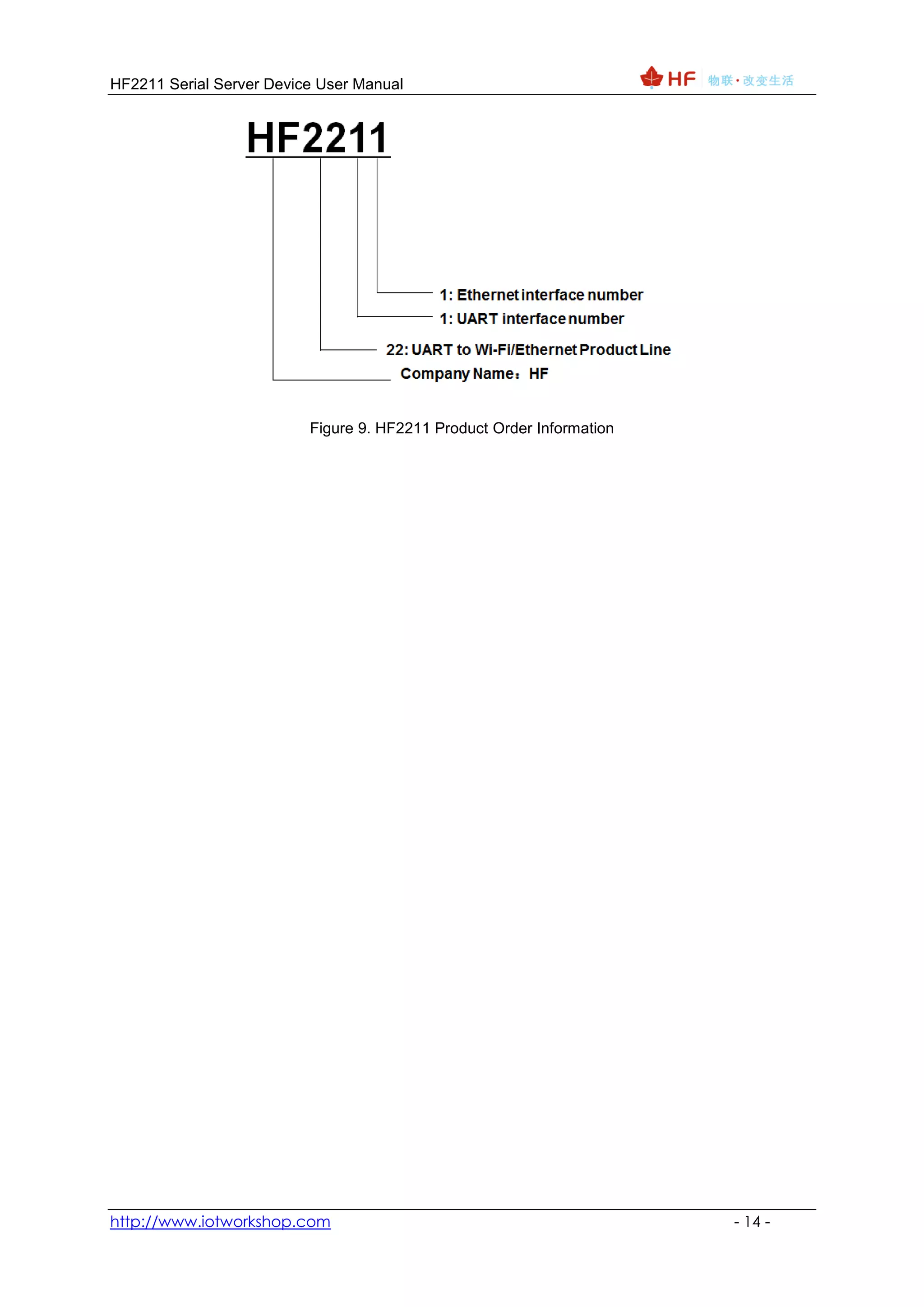
2. Details on its hardware including definitions of its pins, interfaces for RS232, RS485, RS422, Ethernet, and mechanical dimensions.
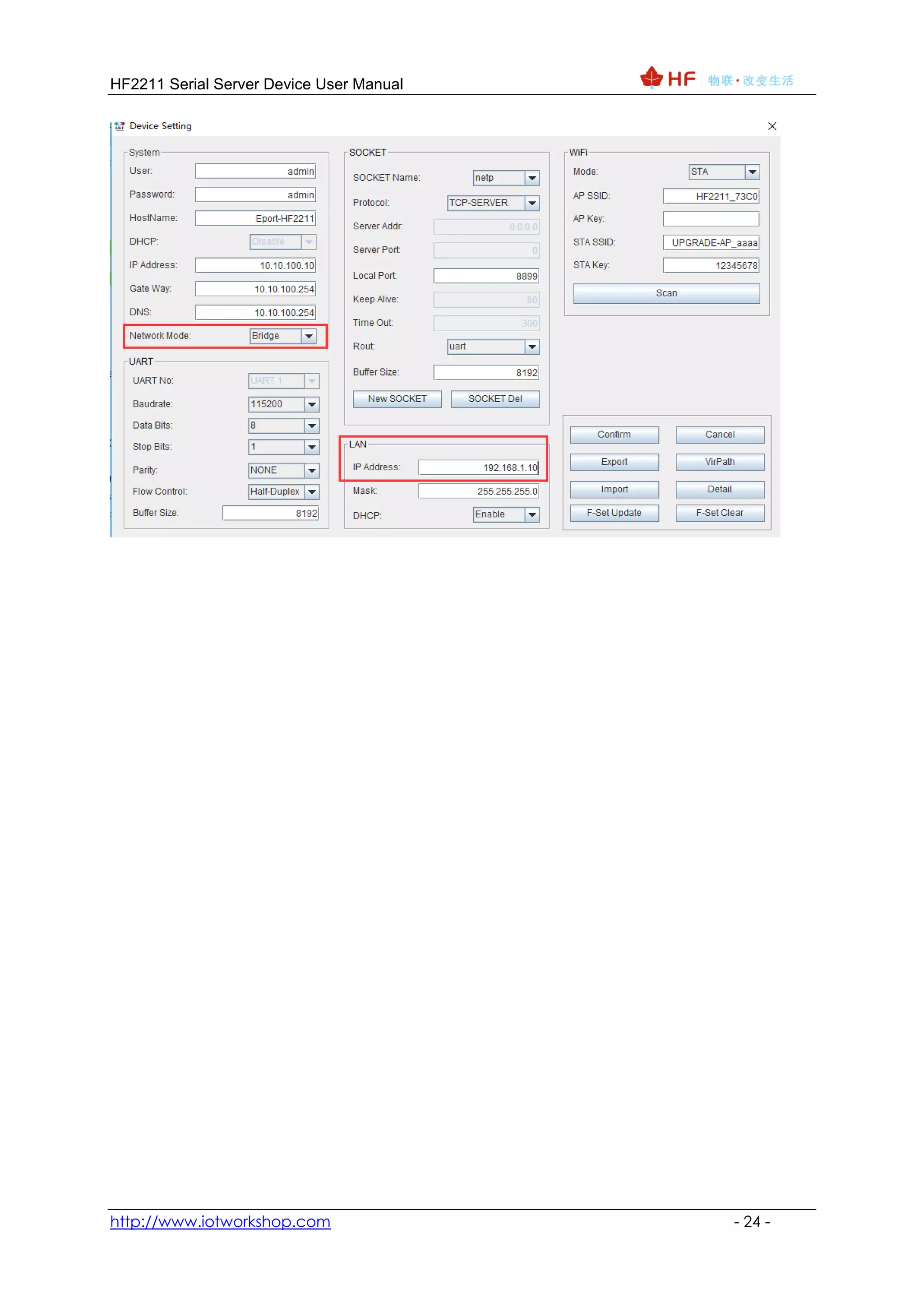
3. Explanations of its network structure including operating as an AP, STA, or AP+STA for wireless connectivity and functions of its Ethernet interface.