Download to read offline


![PRELIMINARY STX3 Users Manual
1/18/2013 PRELIMINARY Subject To Change without Notice P a g e | 18
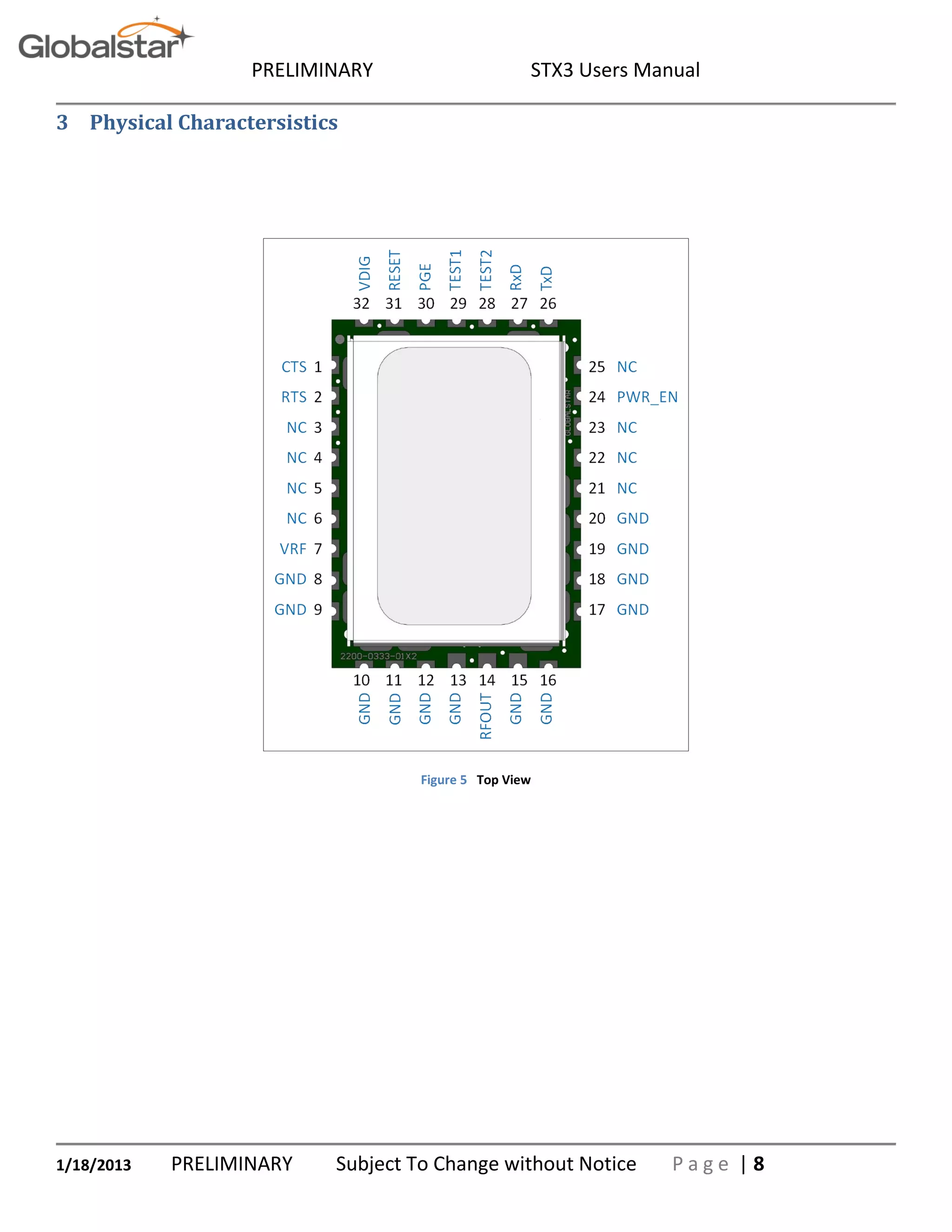
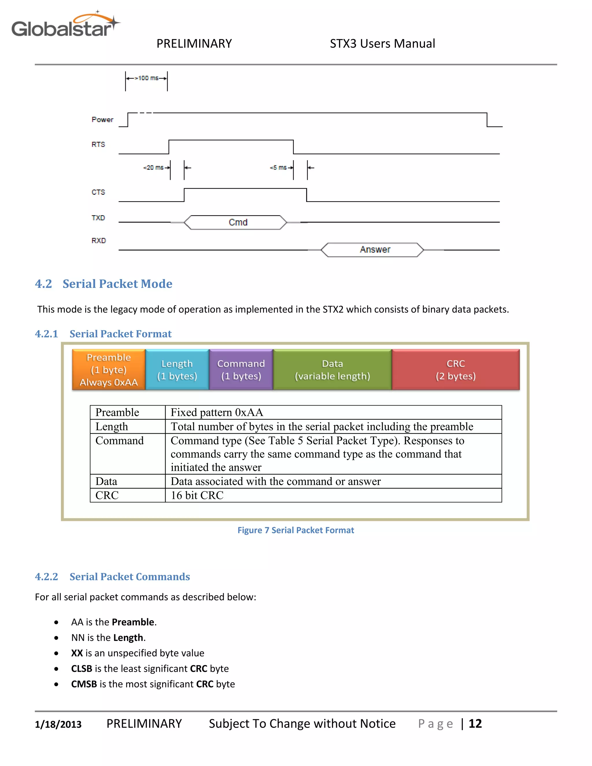
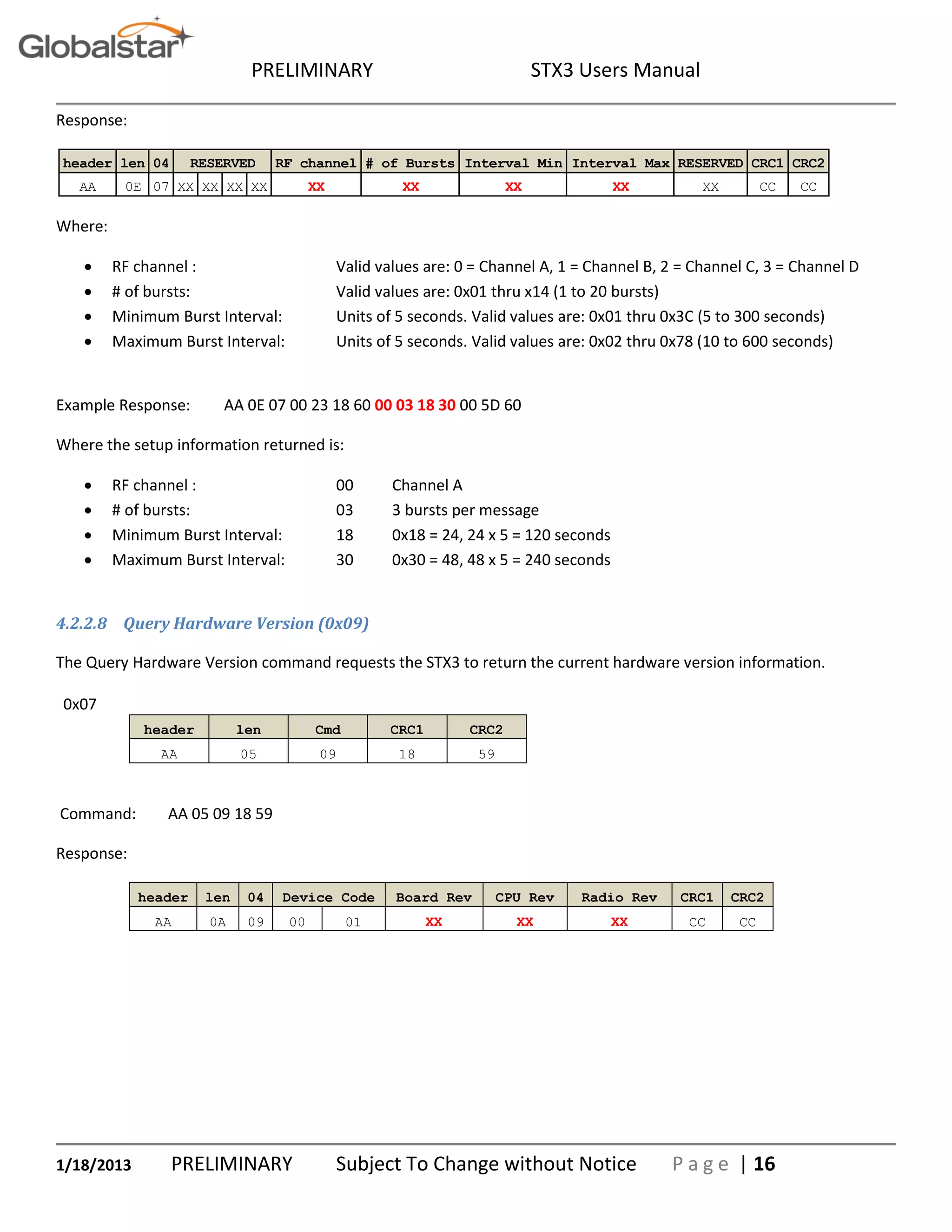
4.3 Example CRC calculation routines for serial packets
The following example is written in the C programming language where:
int = 32 bits, short = 16 bits, char = 8 bits
unsigned short crc16_lsb(unsigned char *pData, int length)
{
unsigned char i;
unsigned short data, crc;
crc = 0xFFFF;
if (length == 0)
return 0;
do
{
data = (unsigned int)0x00FF & *pData++;
crc = crc ^ data;
for (i = 8; i > 0; i--)
{
if (crc & 0x0001)
crc = (crc >> 1) ^ 0x8408;
else
crc >>= 1;
}
}while (--length);
crc = ~crc;
return (crc);
}
USAGE: calculate the CRC for a message and update the message CRC
unsigned short crc = crc16_lsb(msg, msg [1]-2);
msg [msg [1]-2] = (unsigned char) (crc&0xFF);
msg [msg [1]-1] = (unsigned char) (crc>>8);](https://image.slidesharecdn.com/stx3-users-manual-140625015235-phpapp02/75/Globalstar_Stx3_users_manual_18-01-2013-18-2048.jpg)
![PRELIMINARY STX3 Users Manual
1/18/2013 PRELIMINARY Subject To Change without Notice P a g e | 19
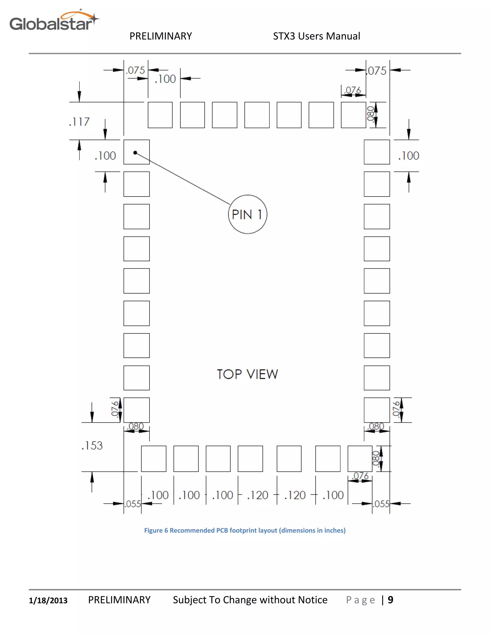
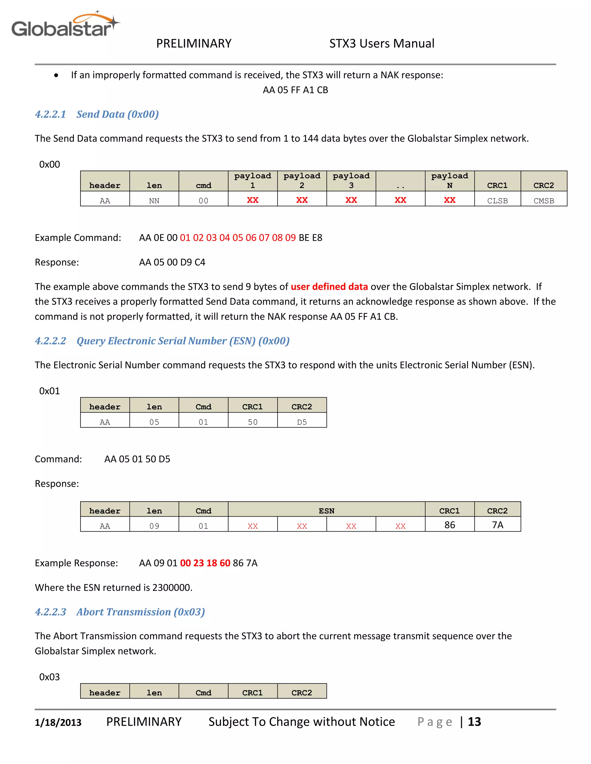
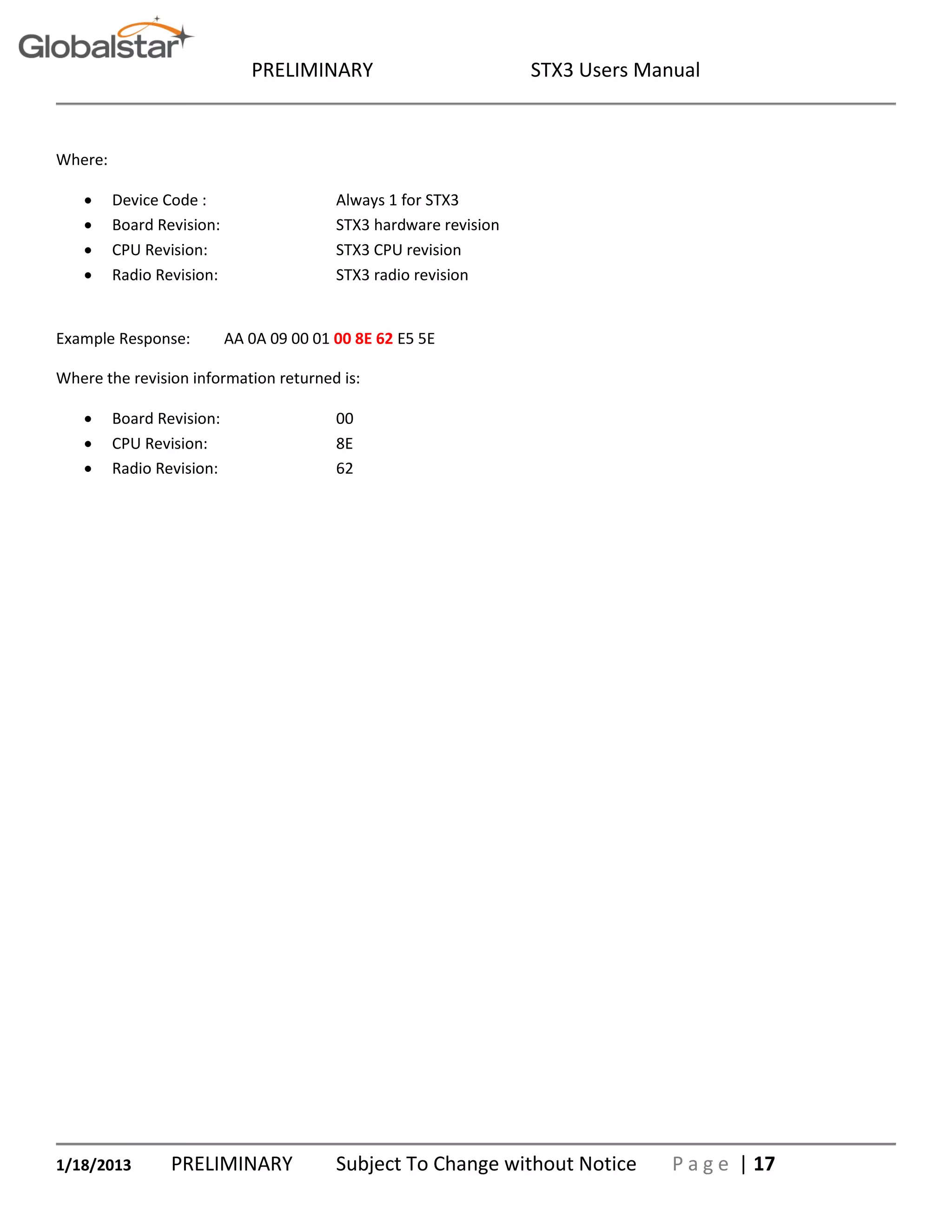
The following example is written in the Java programming language:
char crc16_lsb(byte pData[], int length)
{
int pData_i = 0;
char s1,s2;
byte i;
char data, crc;
crc = (char) 0xFFFF;
if (length == 0)
return 0;
do
{
data = (char)((char)0x00FF & pData[pData_i++]);
crc = (char)(crc ^ data);
for (i = 8; i > 0; i--)
{
if ((crc & 0x0001) != 0)
crc = (char)((crc >> 1) ^ 0x8408);
else
crc >>= 1;
}
}while (--length != 0);
crc = (char)~crc;
return (crc);
}
USAGE: calculate the CRC for a message and update the message CRC
byte msg[]; int len;
char crc = crc16_lsb(msg,len-2);
msg[len-2] = (byte)((short)crc & (short)0xff);
msg[len-1] = (byte)((short)crc >> 8);](https://image.slidesharecdn.com/stx3-users-manual-140625015235-phpapp02/75/Globalstar_Stx3_users_manual_18-01-2013-19-2048.jpg)

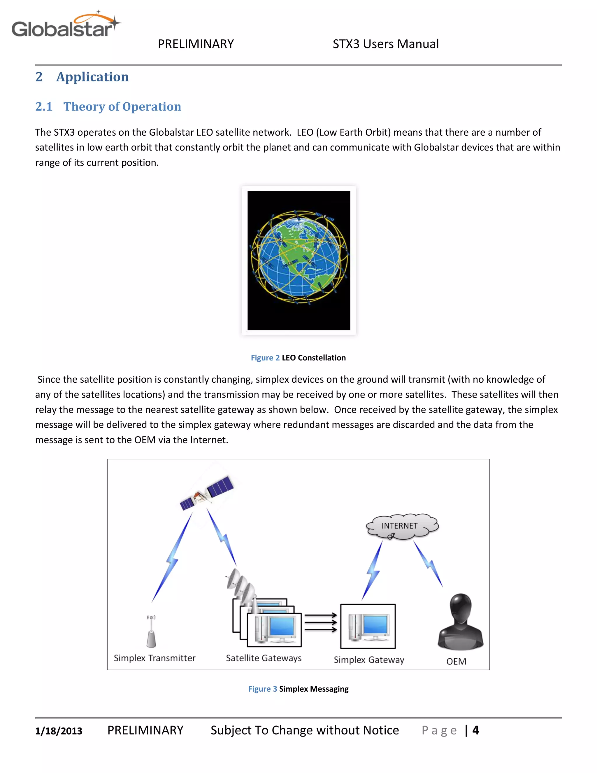
The STX3 Users Manual provides detailed technical specifications and operational guidelines for the STX3 satellite transmitter module, designed for transmitting user-defined data to the Globalstar satellite network. It describes the module's physical characteristics, application programming interface, operation theory, and implementation details, including serial packet formats and command structures. This manual serves as a resource for engineers and technical management familiar with basic engineering practices.


