The document provides a detailed overview of Francis turbines, focusing on their main components, velocity triangles, and efficiency calculations. It discusses aspects such as velocity at different points, forces exerted by jets on the turbine buckets, and the work done by the jet on the runner. Additionally, it covers the definitions of hydraulic, mechanical, and overall efficiencies relevant to turbine performance.


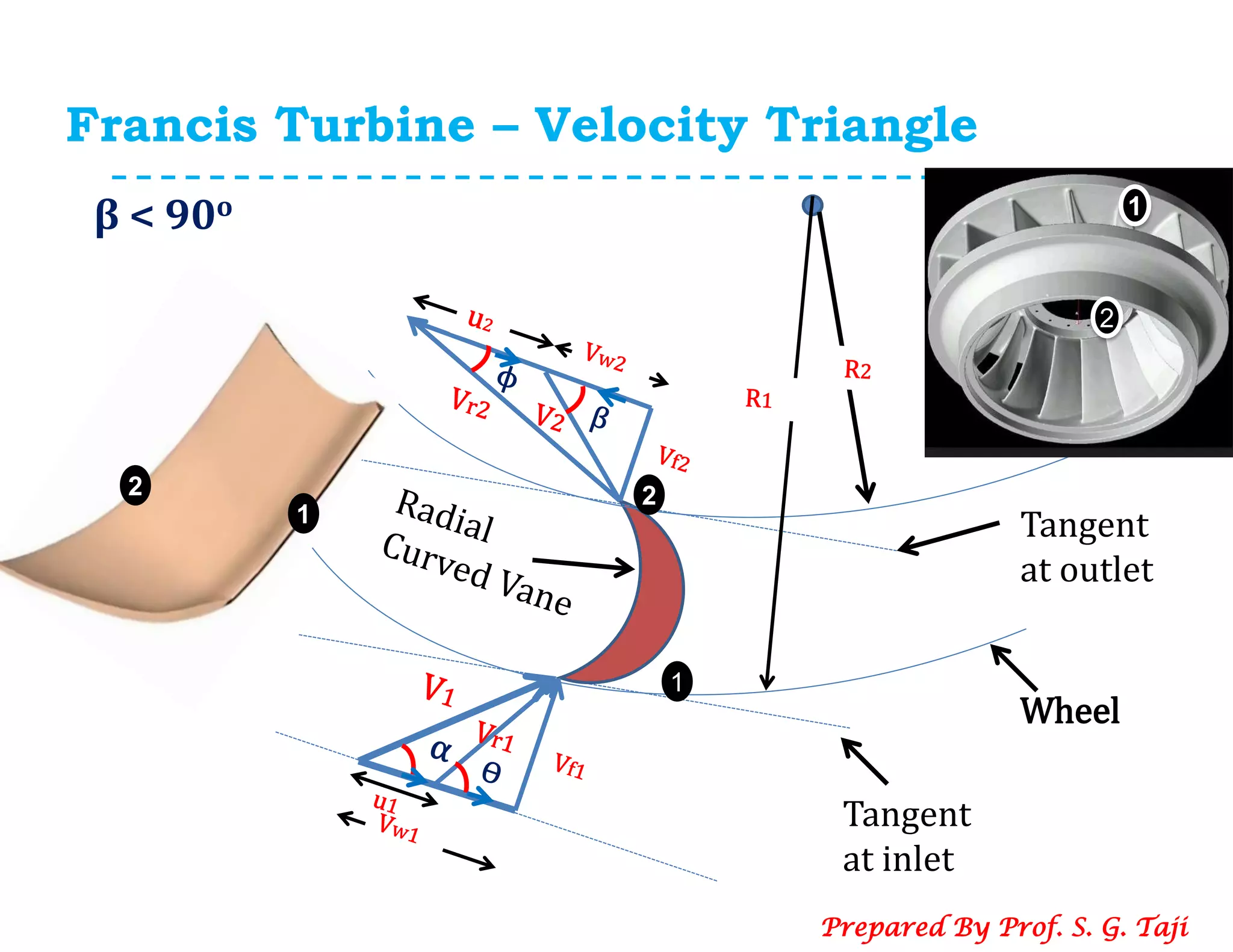


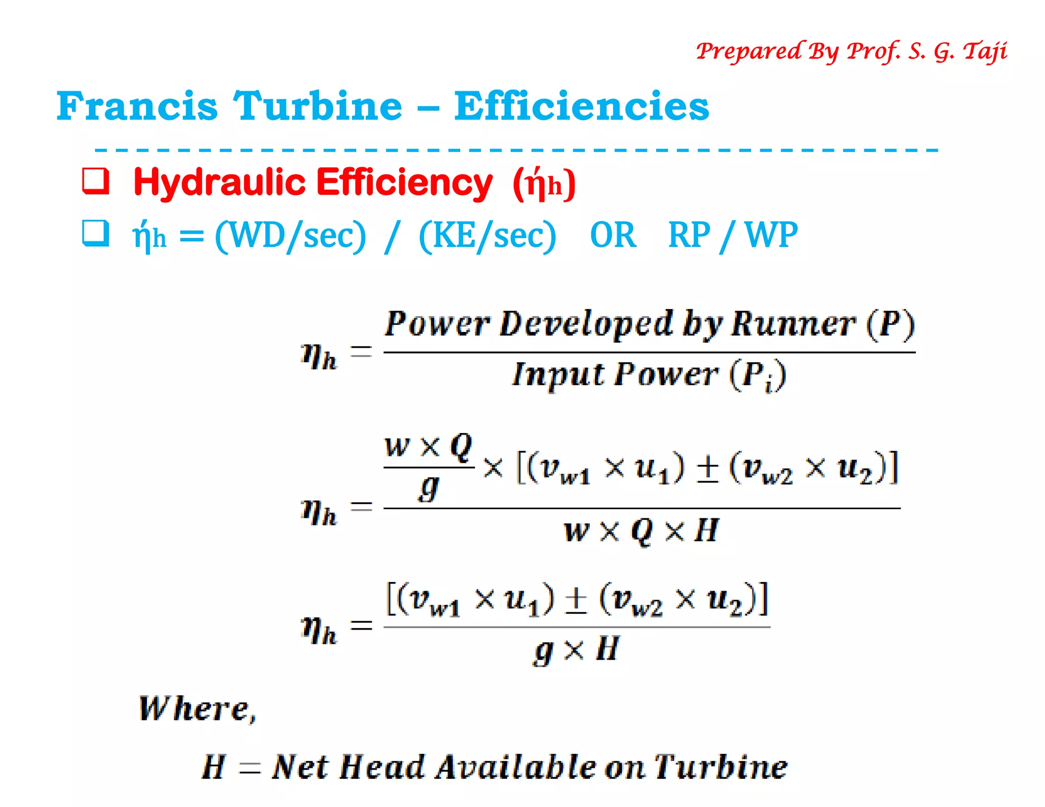
![Francis Turbine – Velocity Triangle
Force exerted by Jet on the Bucket (β<90O )
Now, Angular Momentum = Momentum x Radius
i. momentum /sec at the inlet = (mass/sec) x (velocity
component in tangential dirn)
= (ρ a V1) x [Vw1]
ii. momentum /sec at the outlet= (mass/sec) x (velocity
component in tangential dirn)
= (ρ a V1) x [-Vw2]
iii. Angular momentum at inlet = (ρ a V1) x [Vw1] x R1
iv. Angular momentum at outlet = (ρ a V1) x [-Vw2] x R2
Prepared By Prof. S. G. Taji](https://image.slidesharecdn.com/5-200618172719/75/Francis-Turbine-8-2048.jpg)
![Francis Turbine – Velocity Triangle
Force exerted by Jet on the Bucket (β<90O )
∴ Fx= Mass of water striking the vane per second ×
(Initial angular momentum – final angular momentum)
Fx = (ρ a V1) x [Vw1 R1] - (ρ a V1) x [-Vw2] x R2
= (ρ a V1) [Vw1 R1 + Vw2 R2]
When, β > 90o Fx (ρ a V1) [Vw1 R1 - Vw2 R2]
In general,
Fx = = (ρ a V1) [Vw1 R1 ± Vw2 R2]
When, β = 90o (Radial discharge at outlet )
Fx = = (ρ a V1) [Vw1 R1]
Prepared By Prof. S. G. Taji](https://image.slidesharecdn.com/5-200618172719/75/Francis-Turbine-9-2048.jpg)
![Francis Turbine – Velocity Triangle
Work Done by Jet on the runner / sec
Work Done /sec = Fx x Angular Velocity (ω)
= (ρ a V1) x [Vw1 R1 ± Vw2R2] x ω
= (ρ a V1) x [Vw1 ω R1 ± Vw2 ω R2]
but, u1 = ωR1 & u2 = ωR2
Work Done /sec = (ρ a V1) x [Vw1 u1 ± Vw2 u2] N-m/s
Power = (ρ a V1) x [Vw1 u1 ± Vw2 u2] N-m/s or watts
When, β = 90o (Radial discharge at outlet )
Work Done /sec = (ρ a V1) x [Vw1 u1]
Prepared By Prof. S. G. Taji](https://image.slidesharecdn.com/5-200618172719/75/Francis-Turbine-10-2048.jpg)