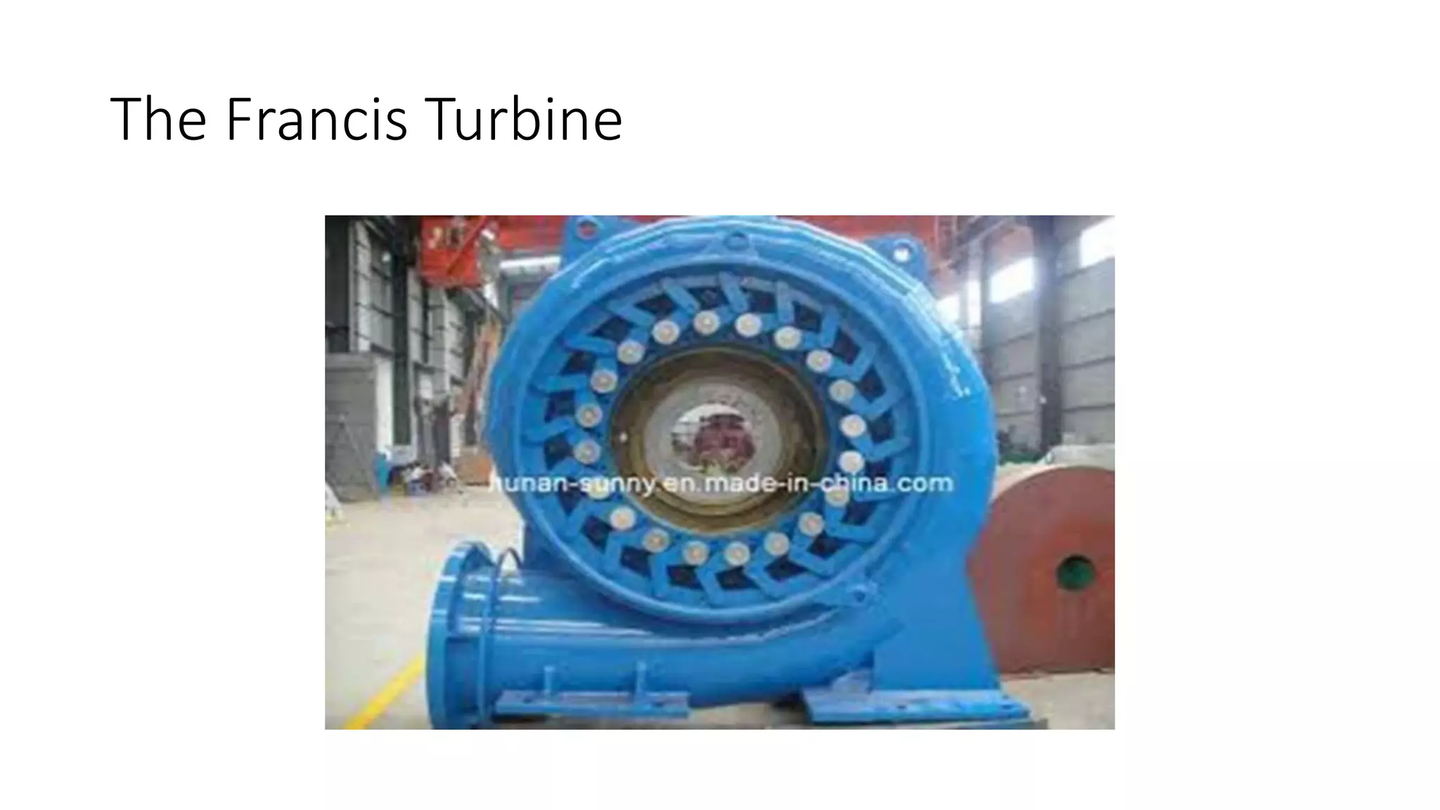
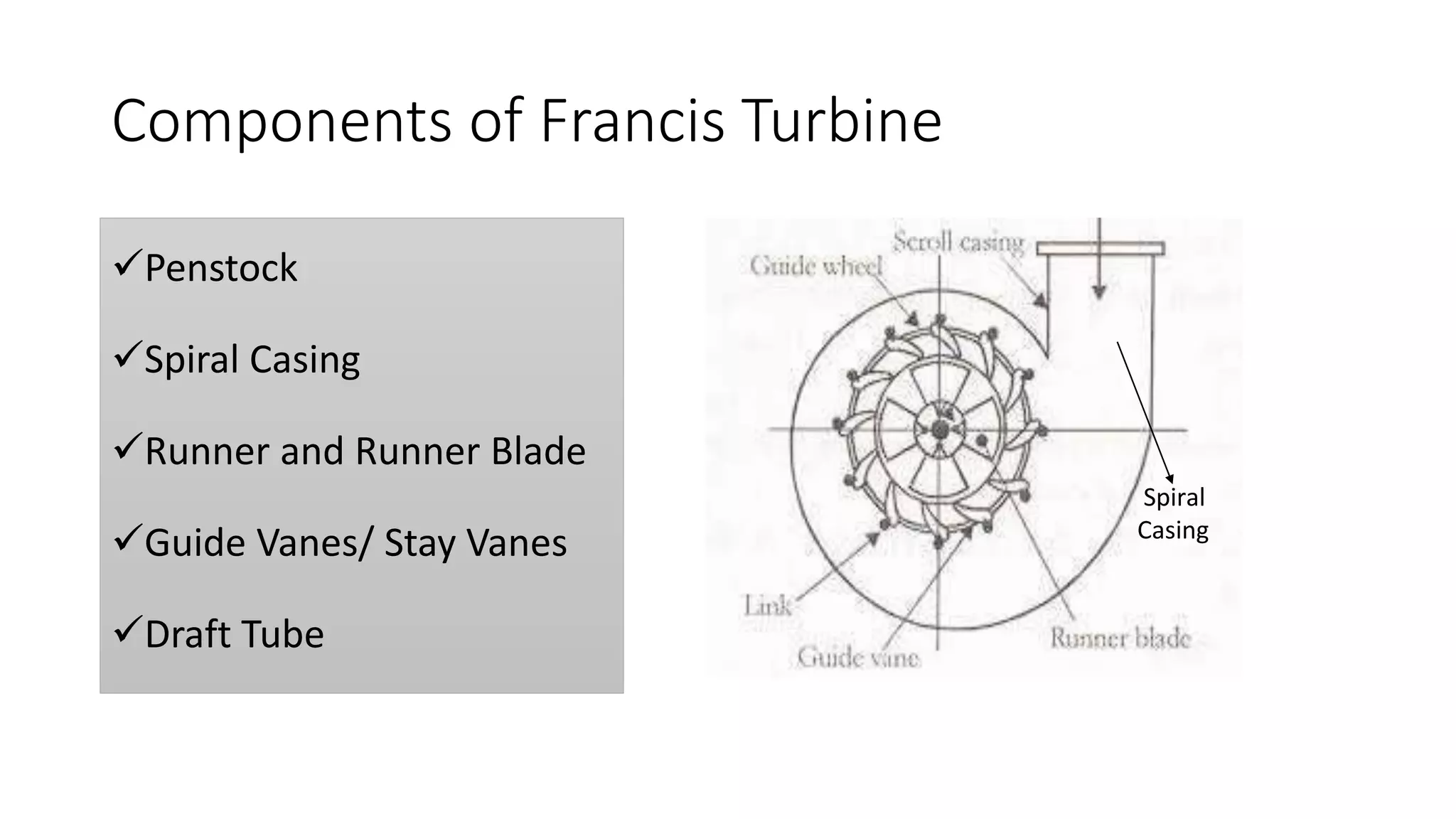
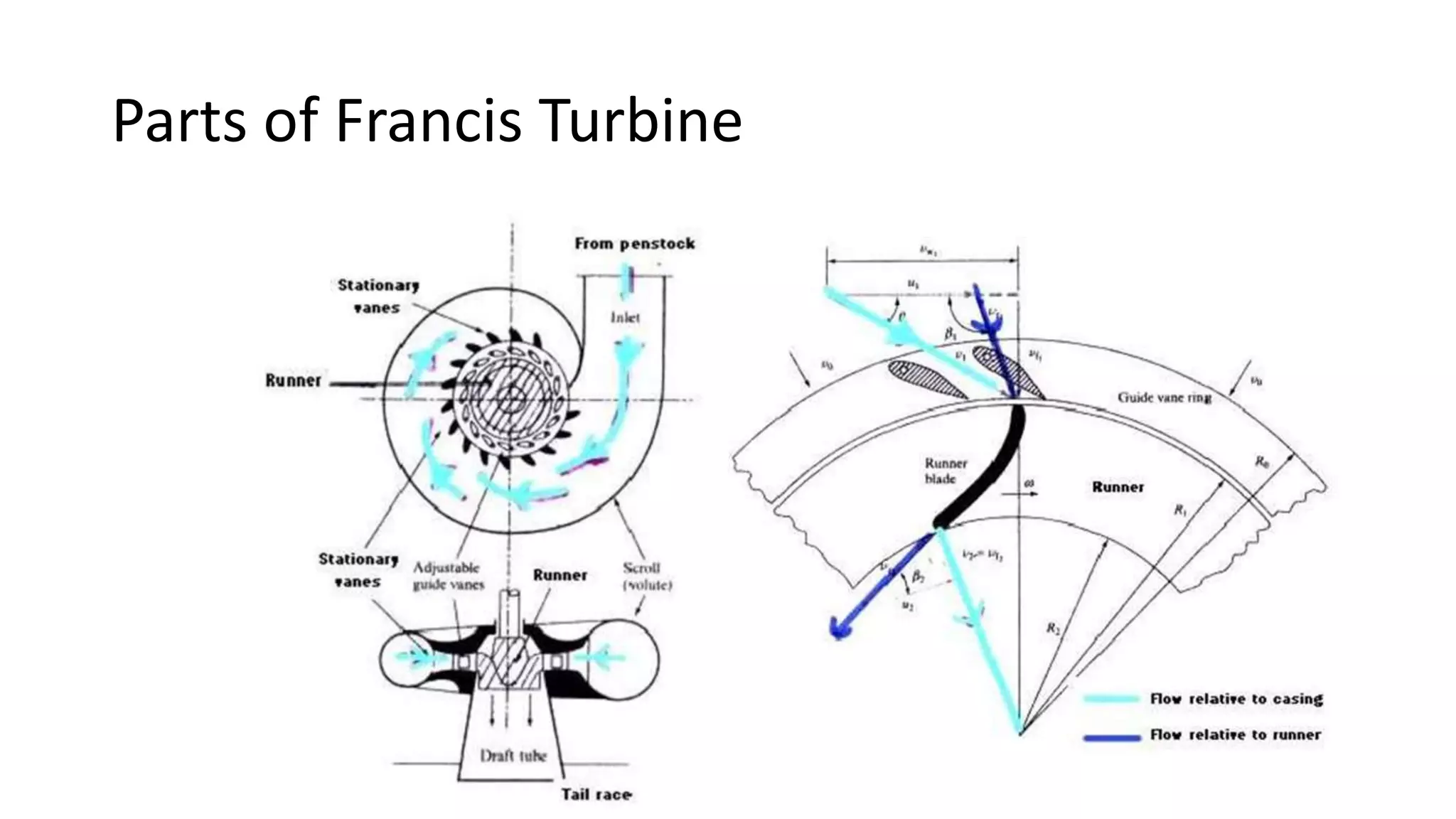
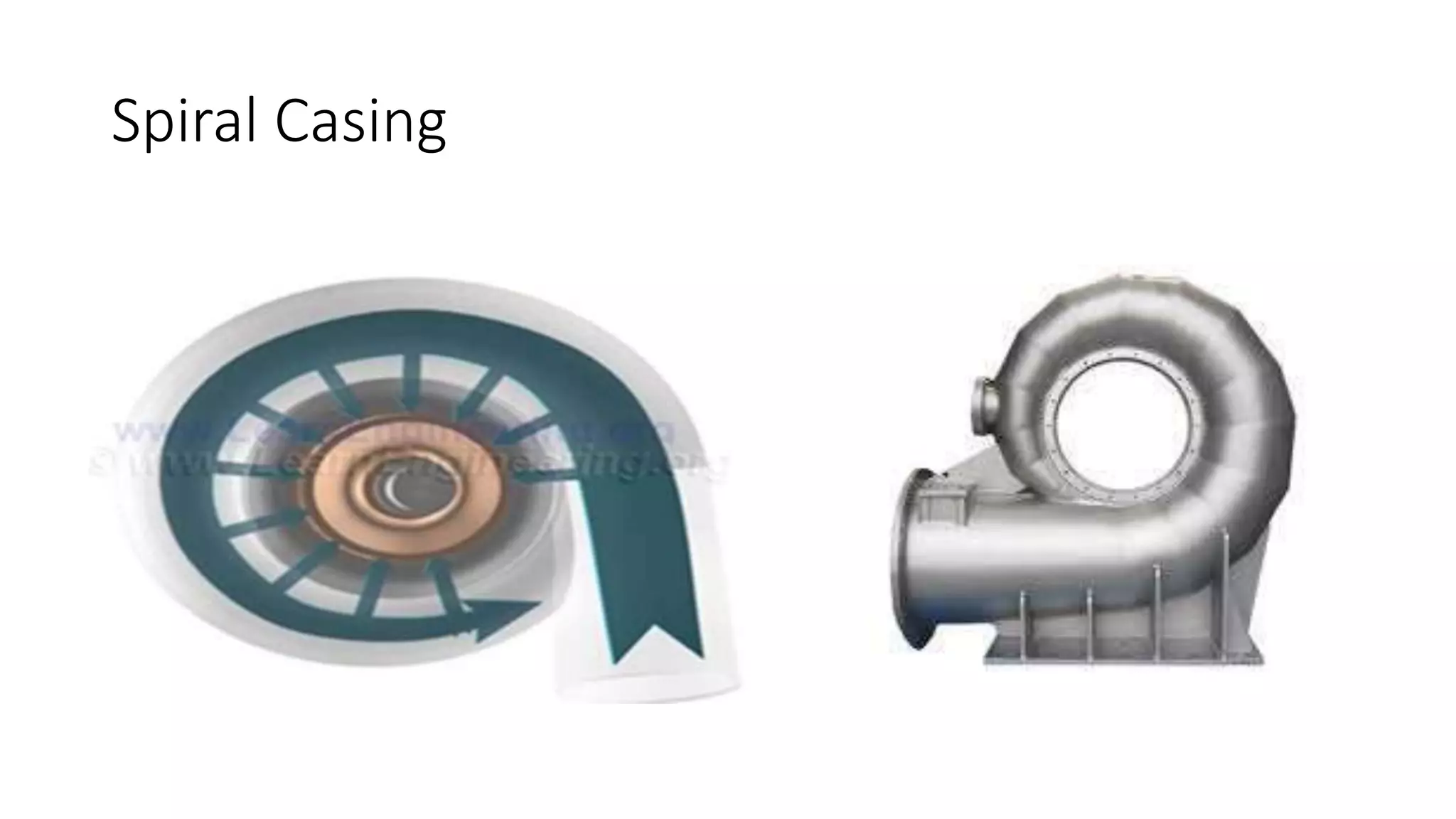
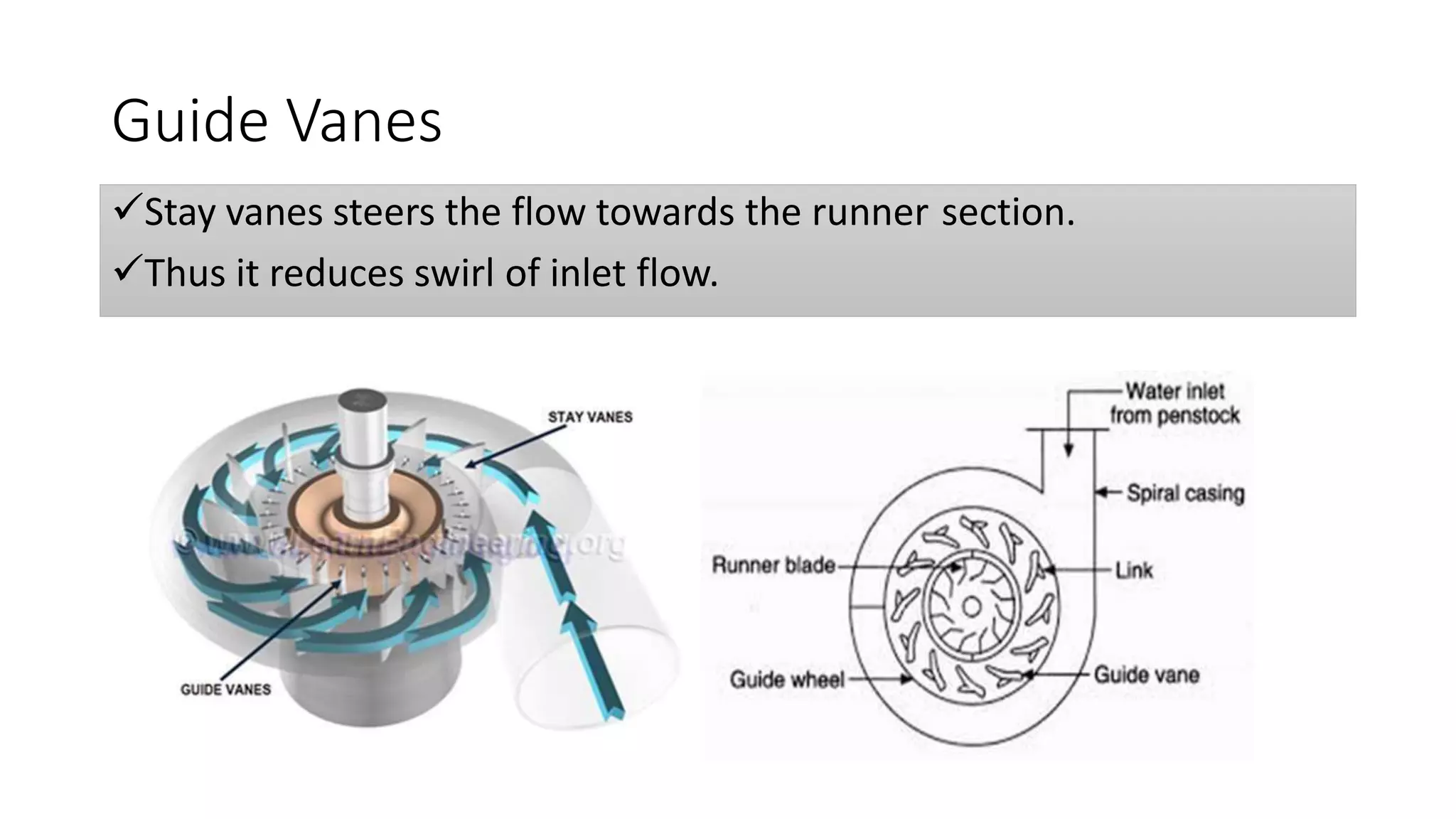
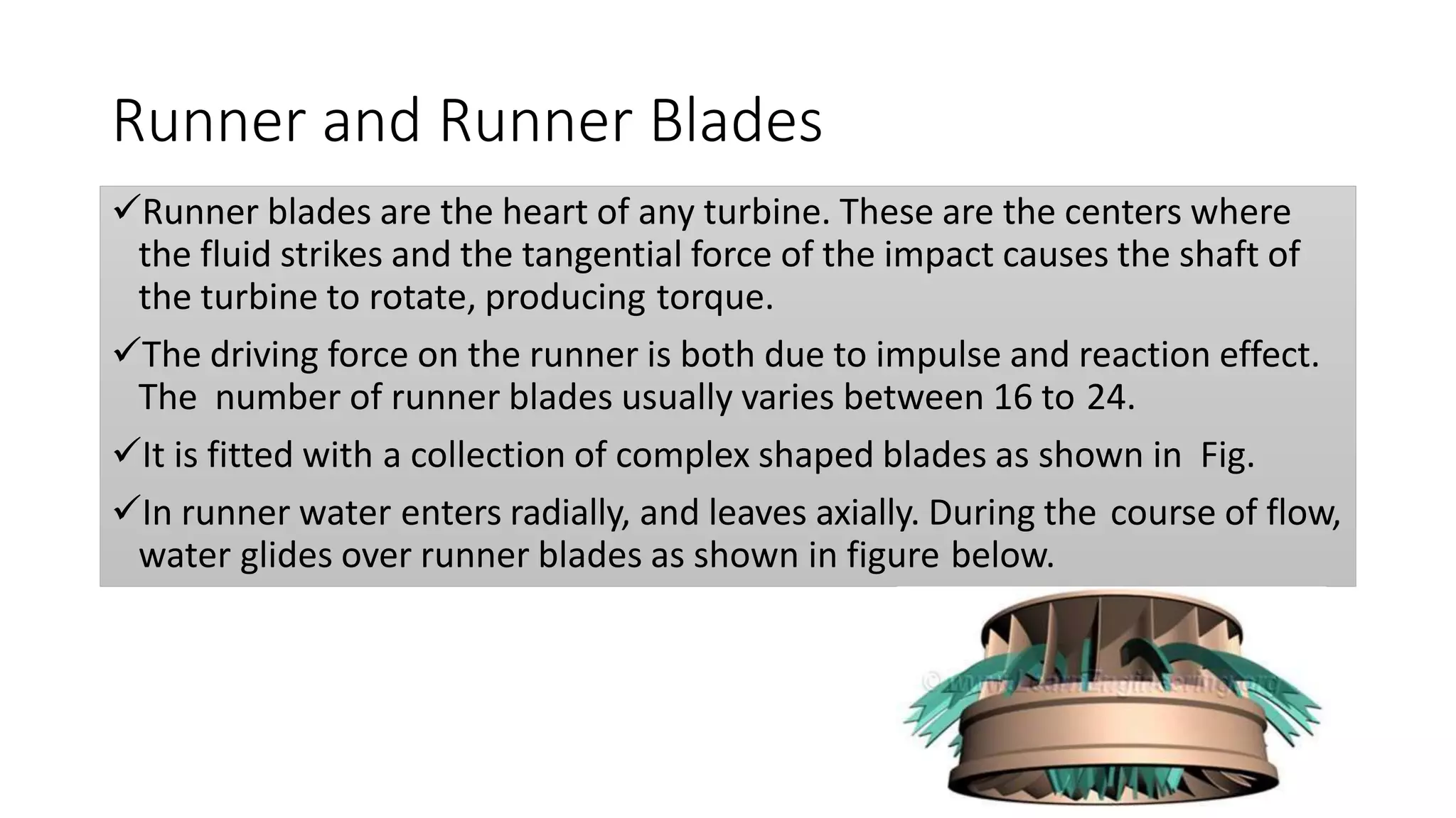
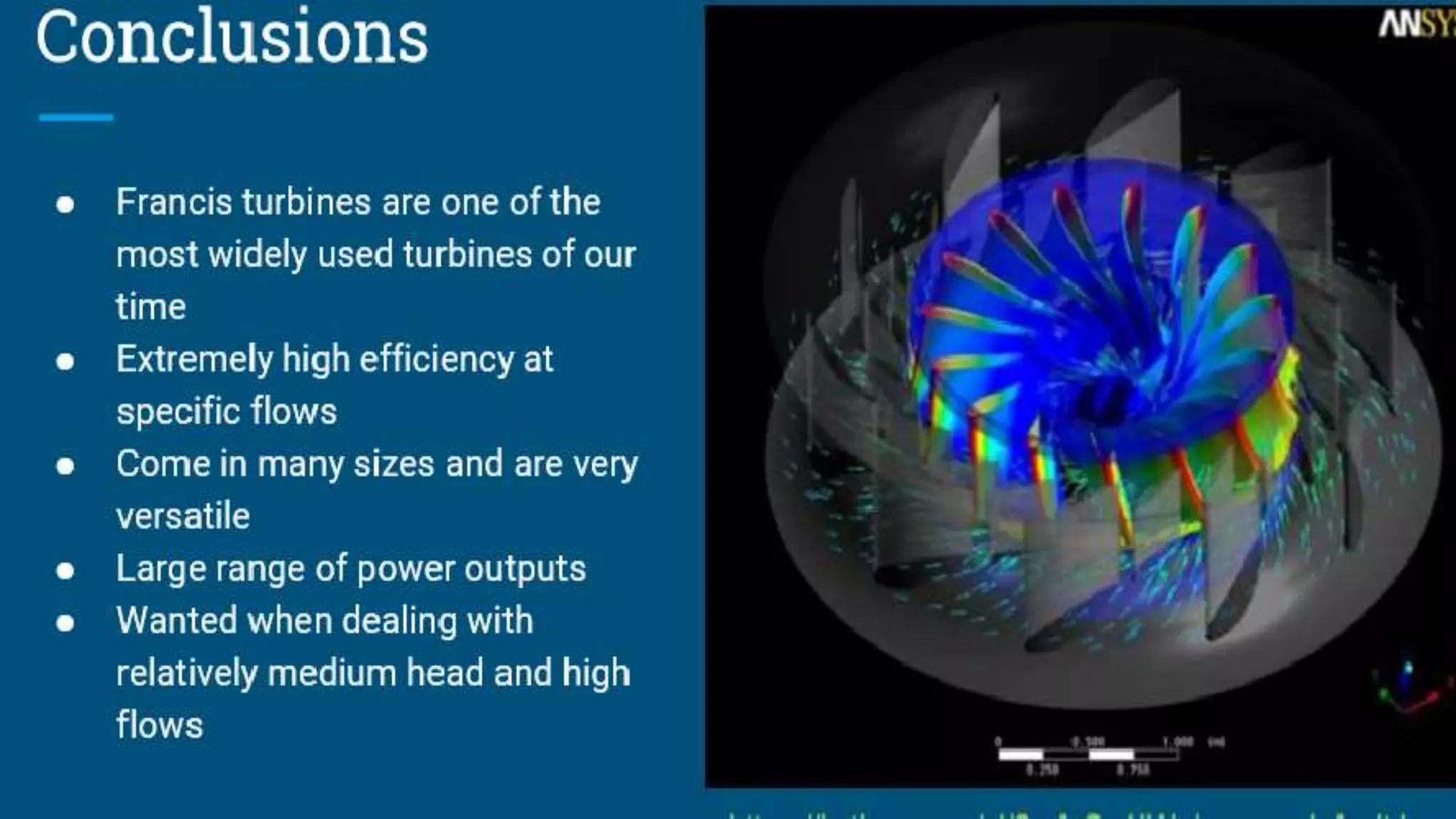
Francis Reaction Turbine
Group Members:
Shahzaib Farooq (Leader) 2KX6-Civil-126
Rafi-ud-din 2KX6-Civil-127
Hassnain Akhtar 2KX6-Civil-131
Farukh Nawaz 2KX6-Civil-142
Francis Reaction Turbine:
Introduction
Turbine:
A turbine is a Rotatory Mechanical Device that extracts energy from
fluid flow and convert it into useful work.
Turbines are used in boat propulsion system, hydroelectric power
generators, and jet aircraft engines.
Used for hydro electric power, i.e. cheapest source of power
generation.
Hydraulic energy Mechanical energy Electrical energy
Power generating device
Basics Types of Turbines
Steam Turbine
Water Turbine
Wind Turbine
Types Based on Energy Used
 Impulse Turbine:
Only kinetic energy of water is used to drive turbine.
• Pelton Turbine
 Reaction Turbine:
Kinetic energy as well as Pressure energy of water is used to
drive turbine.
• Francis Turbine
Introduction
Francis turbines are the most common water turbine in use today.
They operate in a water head from 10 to 700 meters (33 to 2,133
feet).
They are primarily used for electrical power production.
The turbine powered generator power output generally ranges from
10 to 750 megawatts
Introduction
History
This turbine was invented by Sir James B. France in Lowell,
Massachusetts, U.S.A.
Studying the Boyden turbine ,Francis was able to redesign it to
increase efficiency.
Boyden Turbine could achieve a 65 percent efficiency.
So, James France redesigned this turbine and
new turbine with 88% efficiency was invented.
This was known as ‘Francis turbine’.
The Boyden Turbine
The Francis Turbine
Components of Francis Turbine
Penstock
Spiral Casing
Runner and Runner Blade
Guide Vanes/ Stay Vanes
Draft Tube
Spiral
Casing
Parts of Francis Turbine
Working
Penstock
It is a large size
conduit which
conveys water
from the upstream
to the
dam/reservoir to
the turbine runner.
Spiral Casing
It constitutes a closed passage whose cross-sectional area gradually
decreases along the flow direction.
Area is Maximum at inlet and nearly zero at exit.
Runner is fitted, inside a spiral casing.
Flow is entered via an inlet nozzle. Flow rate of water will get reduced
along length of casing, since water is drawn into the runner.
But decreasing area of spiral casing will make sure that, flow is
entered to runner region almost at uniform velocity
Spiral Casing
Guide Vanes
Stay vanes and guide vanes are fitted at entrance of runner.
These vanes direct the water on to the runner at an angle appropriate
to the design, the motion of them is given by means of hand wheel or
by a governor.
The primary function of the guide or stay vanes is to convert the
pressure energy of the fluid into the momentum energy/Kinetic
energy.
It also serves to direct the flow at design angles to the runner blades.
Flow which is coming from the casing, meets stay vanes, they are
fixed.
Guide Vanes
Stay vanes steers the flow towards the runner section.
Thus it reduces swirl of inlet flow.
Guide Vanes
Guide vanesGuide vanesGuide vanesGuide vanesGuide vanesGuide vanes
Runner inlet
(Φ 0.870m)
Guide vane outlet for designα)
(Φ 0.913m)
Closed
Position
Max. Opening
Position
Operation of Guide Vanes
Guide vane at Design
Position = 12.21°
Guide vane at closed position
Guide vane at Max. open
Position = 18°
.
Motion of Water Relative to blade:
Runner and Runner Blades
Runner blades are the heart of any turbine. These are the centers where
the fluid strikes and the tangential force of the impact causes the shaft of
the turbine to rotate, producing torque.
The driving force on the runner is both due to impulse and reaction effect.
The number of runner blades usually varies between 16 to 24.
It is fitted with a collection of complex shaped blades as shown in Fig.
In runner water enters radially, and leaves axially. During the course of flow,
water glides over runner blades as shown in figure below.
Runner and Runner Blades
Blades of Francis turbine are specially shaped as shown in figure. It is
clear from the figure that shape of blade cross-section is of thin
airfoils.
So, when water flows over it, a low pressure will be induced on one
side, and high pressure on the other side.
This will result in a lift force.
Runner and Runner Blade
It is having a bucket kind of shape towards the outlet.
When water will hit, then it produce an impulse force before leaving
the runner.
Both impulse force and lift force will make the runner rotate.
Therefore, as water flows over runner blades both its kinetic and
pressure energy will come down.
Since flow is entering radially and leaves axially, they are also called
‘mixed flow turbine’.
Runner is connected to generator, via a shaft, for electricity
production.
Runner and Runner Blade
Runner with Generator
Draft Tube
The draft tube is gradually expanding conduit which discharges
water from the turbine, passing through the runner to the tail race.
Its primary function is to reduce the velocity of discharged water to
minimize the loss of kinetic energy at the outlet.
This permits the turbine to be set above the tail water without
appreciable drop of available head.
Governing Mechanism
When the load condition on the turbine changes then the position of
guide vane also changes to control water flow rate.
It also makes sure that power production is synchronized with power
demand.
Guide vanes also control flow angle to inlet portion of runner blade.
Thus guide vanes make sure that inlet flow angle is at optimum angle
of attack for maximum power extraction from fluid.
Francis Turbine Power Plant
Francis Installation
Cavitation
Cavitation is an important problem in hydraulic machines that
negativelyaffects their performance and may cause damages.
Cavitation is a phenomenon which manifests itself in the pitting of
the metallic surfaces of turbine parts because of the formation of
cavities.
The reaction turbines operate under low and medium head with high
specific speed and operate under variable pressure.
Cavitation in hydraulic machines negatively affects their performance
and may causes severe damages.
Damages Caused by Cavitation
Erosion of Water from Turbine parts.
Distortion of Blade Angle
Loss of Efficiency Due to Erosion/Distortion.
(A) Draft Tube Swril (B) Travelling Edge Cavitation
(C) Leading Edge Cavitation (D) Inter-blade Vortex Cavitation
Efficiency of Turbine
Hydraulic Efficiency- It is ratio of power developed bythe
runner of a turbine to the power supplied by the water at the
inlet.
Mechanical Efficiency– It is ratio of power available at the
shaft to power developed at therunner.
Overall Efficiency- It is ratio of power available at the shaft
of the turbine to the power supplied by the water at the inlet
of the turbine.
Relevant Equations
Recent Advancements
New types of designs are developed to reduce cost and
complexity of mechanism.
Modified turbine include Inline Linkless Francis Turbine,
Cross-flow Turbine, etc.
These new turbine require less space, simplified designs, less
moving parts, etc.
Practical Uses
• Guri Hydroelectric Power Plant in Orinoco,
Venezuela
Hope you Like It…
Any Questions…??

Francis reaction turbine

  • 2.
  • 3.
    Group Members: Shahzaib Farooq(Leader) 2KX6-Civil-126 Rafi-ud-din 2KX6-Civil-127 Hassnain Akhtar 2KX6-Civil-131 Farukh Nawaz 2KX6-Civil-142
  • 4.
  • 5.
  • 6.
    Turbine: A turbine isa Rotatory Mechanical Device that extracts energy from fluid flow and convert it into useful work. Turbines are used in boat propulsion system, hydroelectric power generators, and jet aircraft engines. Used for hydro electric power, i.e. cheapest source of power generation. Hydraulic energy Mechanical energy Electrical energy Power generating device
  • 7.
    Basics Types ofTurbines Steam Turbine Water Turbine Wind Turbine
  • 8.
    Types Based onEnergy Used  Impulse Turbine: Only kinetic energy of water is used to drive turbine. • Pelton Turbine  Reaction Turbine: Kinetic energy as well as Pressure energy of water is used to drive turbine. • Francis Turbine
  • 9.
    Introduction Francis turbines arethe most common water turbine in use today. They operate in a water head from 10 to 700 meters (33 to 2,133 feet). They are primarily used for electrical power production. The turbine powered generator power output generally ranges from 10 to 750 megawatts
  • 10.
  • 11.
    History This turbine wasinvented by Sir James B. France in Lowell, Massachusetts, U.S.A. Studying the Boyden turbine ,Francis was able to redesign it to increase efficiency. Boyden Turbine could achieve a 65 percent efficiency. So, James France redesigned this turbine and new turbine with 88% efficiency was invented. This was known as ‘Francis turbine’.
  • 12.
  • 13.
  • 14.
    Components of FrancisTurbine Penstock Spiral Casing Runner and Runner Blade Guide Vanes/ Stay Vanes Draft Tube Spiral Casing
  • 15.
  • 16.
  • 17.
    Penstock It is alarge size conduit which conveys water from the upstream to the dam/reservoir to the turbine runner.
  • 18.
    Spiral Casing It constitutesa closed passage whose cross-sectional area gradually decreases along the flow direction. Area is Maximum at inlet and nearly zero at exit. Runner is fitted, inside a spiral casing. Flow is entered via an inlet nozzle. Flow rate of water will get reduced along length of casing, since water is drawn into the runner. But decreasing area of spiral casing will make sure that, flow is entered to runner region almost at uniform velocity
  • 19.
  • 20.
    Guide Vanes Stay vanesand guide vanes are fitted at entrance of runner. These vanes direct the water on to the runner at an angle appropriate to the design, the motion of them is given by means of hand wheel or by a governor. The primary function of the guide or stay vanes is to convert the pressure energy of the fluid into the momentum energy/Kinetic energy. It also serves to direct the flow at design angles to the runner blades. Flow which is coming from the casing, meets stay vanes, they are fixed.
  • 21.
    Guide Vanes Stay vanessteers the flow towards the runner section. Thus it reduces swirl of inlet flow.
  • 22.
  • 23.
    Guide vanesGuide vanesGuidevanesGuide vanesGuide vanesGuide vanes Runner inlet (Φ 0.870m) Guide vane outlet for designα) (Φ 0.913m) Closed Position Max. Opening Position
  • 24.
    Operation of GuideVanes Guide vane at Design Position = 12.21° Guide vane at closed position Guide vane at Max. open Position = 18° .
  • 25.
    Motion of WaterRelative to blade:
  • 26.
    Runner and RunnerBlades Runner blades are the heart of any turbine. These are the centers where the fluid strikes and the tangential force of the impact causes the shaft of the turbine to rotate, producing torque. The driving force on the runner is both due to impulse and reaction effect. The number of runner blades usually varies between 16 to 24. It is fitted with a collection of complex shaped blades as shown in Fig. In runner water enters radially, and leaves axially. During the course of flow, water glides over runner blades as shown in figure below.
  • 27.
    Runner and RunnerBlades Blades of Francis turbine are specially shaped as shown in figure. It is clear from the figure that shape of blade cross-section is of thin airfoils. So, when water flows over it, a low pressure will be induced on one side, and high pressure on the other side. This will result in a lift force.
  • 28.
    Runner and RunnerBlade It is having a bucket kind of shape towards the outlet. When water will hit, then it produce an impulse force before leaving the runner. Both impulse force and lift force will make the runner rotate. Therefore, as water flows over runner blades both its kinetic and pressure energy will come down. Since flow is entering radially and leaves axially, they are also called ‘mixed flow turbine’. Runner is connected to generator, via a shaft, for electricity production.
  • 29.
  • 30.
  • 31.
    Draft Tube The drafttube is gradually expanding conduit which discharges water from the turbine, passing through the runner to the tail race. Its primary function is to reduce the velocity of discharged water to minimize the loss of kinetic energy at the outlet. This permits the turbine to be set above the tail water without appreciable drop of available head.
  • 32.
    Governing Mechanism When theload condition on the turbine changes then the position of guide vane also changes to control water flow rate. It also makes sure that power production is synchronized with power demand. Guide vanes also control flow angle to inlet portion of runner blade. Thus guide vanes make sure that inlet flow angle is at optimum angle of attack for maximum power extraction from fluid.
  • 33.
  • 34.
  • 35.
    Cavitation Cavitation is animportant problem in hydraulic machines that negativelyaffects their performance and may cause damages. Cavitation is a phenomenon which manifests itself in the pitting of the metallic surfaces of turbine parts because of the formation of cavities. The reaction turbines operate under low and medium head with high specific speed and operate under variable pressure. Cavitation in hydraulic machines negatively affects their performance and may causes severe damages.
  • 36.
    Damages Caused byCavitation Erosion of Water from Turbine parts. Distortion of Blade Angle Loss of Efficiency Due to Erosion/Distortion.
  • 38.
    (A) Draft TubeSwril (B) Travelling Edge Cavitation (C) Leading Edge Cavitation (D) Inter-blade Vortex Cavitation
  • 39.
    Efficiency of Turbine HydraulicEfficiency- It is ratio of power developed bythe runner of a turbine to the power supplied by the water at the inlet. Mechanical Efficiency– It is ratio of power available at the shaft to power developed at therunner. Overall Efficiency- It is ratio of power available at the shaft of the turbine to the power supplied by the water at the inlet of the turbine.
  • 40.
  • 45.
    Recent Advancements New typesof designs are developed to reduce cost and complexity of mechanism. Modified turbine include Inline Linkless Francis Turbine, Cross-flow Turbine, etc. These new turbine require less space, simplified designs, less moving parts, etc.
  • 46.
  • 48.
    • Guri HydroelectricPower Plant in Orinoco, Venezuela
  • 50.
    Hope you LikeIt… Any Questions…??