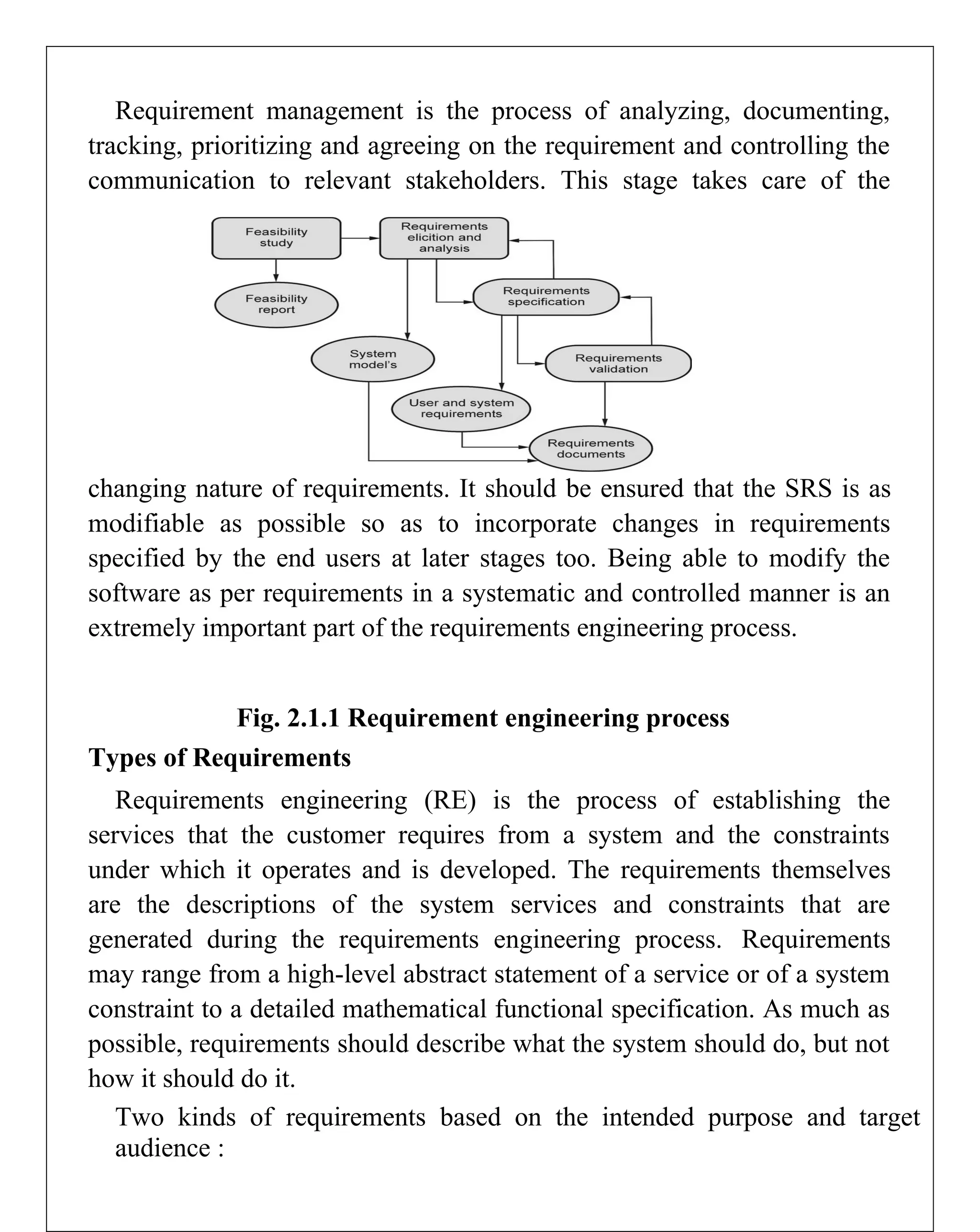
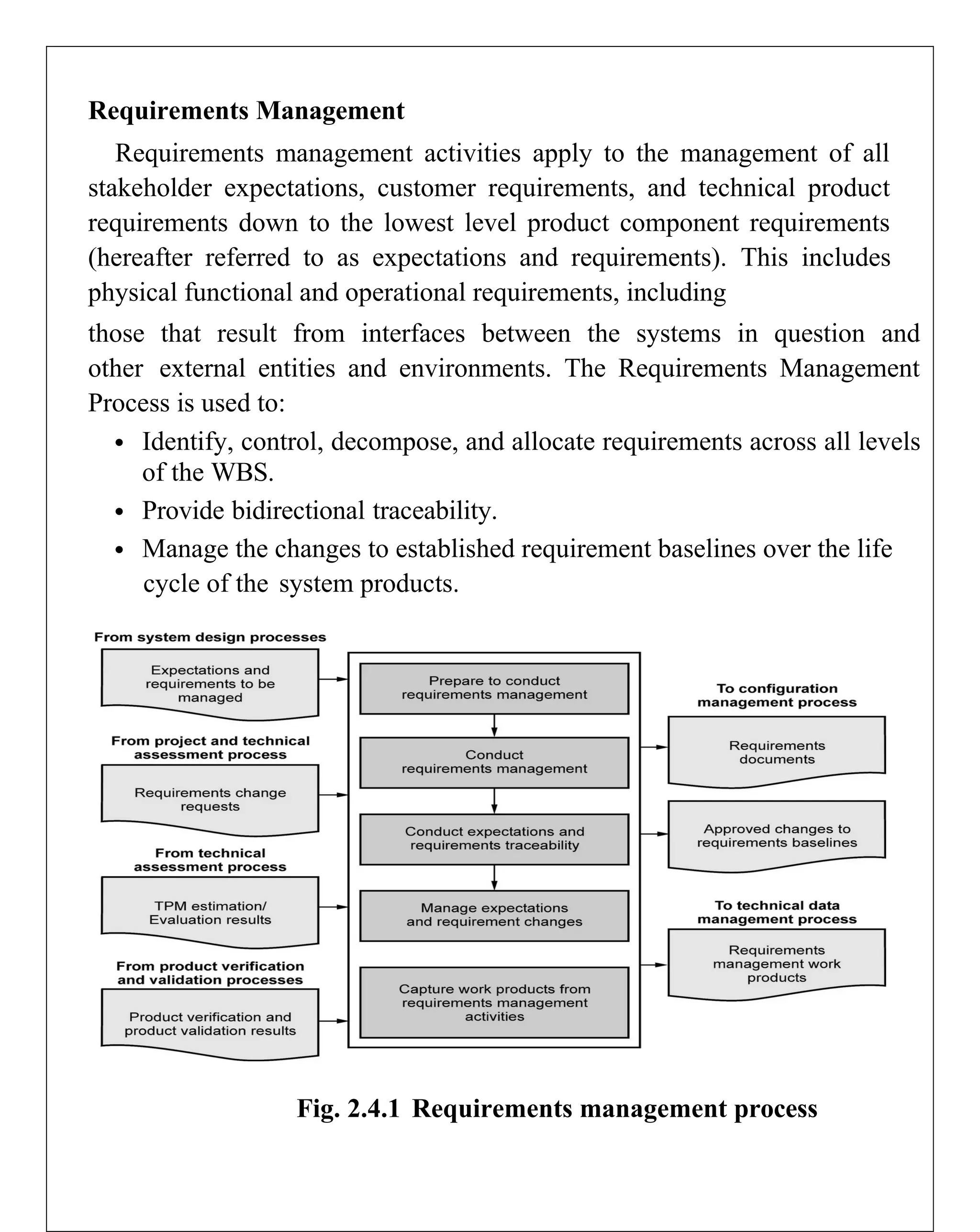
UNIT-2
Requirements and System
Requirement Engineering
Definition
Requirement Engineering is the process of defining, documenting and
maintaining the requirements. It is a process of gathering and defining
service provided by the system.
Requirements Engineering Process consists of the following main
activities :
 Requirements elicitation
 Requirements specification
 Requirements verification and validation
 Requirements management
Requirements Elicitation :
It is related to the various ways used to gain knowledge about the
project domain and requirements. The various sources of domain
knowledge include customers, business manuals, the existing software of
same type, standards and other stakeholders of the project.
The techniques used for requirements elicitation include interviews,
brainstorming, task analysis, Delphi technique, prototyping, etc. Some of
these are discussed here. Elicitation does not produce formal models of
the requirements understood. Instead, it widens the domain knowledge of
the analyst and thus helps in providing input to the next stage.
Requirements specification :
This activity is used to produce formal software requirement models.
All the requirements including the functional as well as the non-functional
requirements and the constraints are specified by these models in totality.
During specification, more knowledge about the problem may be required
which can again trigger the elicitation process.
The models used at this stage include ER diagrams, data flow
diagrams(DFDs), function decomposition diagrams(FDDs), data
dictionaries, etc.
Requirements verification and validation :
Verification: It refers to the set of tasks that ensures that the software
correctly implements a specific function.
Validation : It refers to a different set of tasks that ensures that the
software that has been built is traceable to customer requirements.If
requirements are not validated, errors in the requirement definitions would
propagate to the successive stages resulting in a lot of modification and
rework.
The main steps for this process include :
The requirements should be consistent with all the other requirements i.e
no two requirements should conflict with each other.
The requirements should be complete in every
sense. The requirements should be practically
achievable.
Requirement management :
Requirement management is the process of analyzing, documenting,
tracking, prioritizing and agreeing on the requirement and controlling the
communication to relevant stakeholders. This stage takes care of the
changing nature of requirements. It should be ensured that the SRS is as
modifiable as possible so as to incorporate changes in requirements
specified by the end users at later stages too. Being able to modify the
software as per requirements in a systematic and controlled manner is an
extremely important part of the requirements engineering process.
Fig. 2.1.1 Requirement engineering process
Types of Requirements
Requirements engineering (RE) is the process of establishing the
services that the customer requires from a system and the constraints
under which it operates and is developed. The requirements themselves
are the descriptions of the system services and constraints that are
generated during the requirements engineering process. Requirements
may range from a high-level abstract statement of a service or of a system
constraint to a detailed mathematical functional specification. As much as
possible, requirements should describe what the system should do, but not
how it should do it.
Two kinds of requirements based on the intended purpose and target
audience :
User requirements
High-level abstract requirements written as statements, in a natural
language plus diagrams, of what services the system is expected to
provide to system users and the constraints under which it must operate.
System requirements
Detailed description of what the system should do including the
software ystem's functions, services, and operational constraints. The
system requirements document (sometimes called a functional
specification) should define exactly what is to be implemented. It may be
part of the contract between the system buyer and the software developers.
Three classes of requirements :
Functional requirements
Statements of services the system should provide, how the system
should react to particular inputs and how the system should behave in
particular situations. May state what the system should not do.
Non-functional requirements
Constraints on the services or functions offered by the system such as
timing constraints, constraints on the development process, standards, etc.
Often apply to the system as a whole rather than individual features or
services.
Domain requirements
Constraints on the system from the domain of operation.
Functional requirements
Functional requirements describe functionality or system services. They
depend on the type of software, expected users and the type of system
where the software is used.
Functional user requirements may be high-level statements of what the
system should do.
Functional system requirements should describe the system services in
detail.
Problems arise when requirements are not precisely stated. Ambiguous
requirements may be interpreted in different ways by developers and
users. In principle, requirements should be both.
Complete : they should include descriptions of all facilities required, and
Consistent : there should be no conflicts or contradictions in the
descriptions of the system facilities.
In practice, it is impossible to produce a complete and consistent
requirements document.
Non-functional requirements
Non-functional requirements define system properties and constraints
e.g. reliability, response time and storage requirements. Constraints are
I/O device capability, system representations, etc. Process requirements
may also be specified mandating a particular IDE, programming language
or development method. Non-functional requirements may be more
critical than functional requirements. If these are not met, the system may
be useless.
Non-functional requirements may affect the overall architecture of a
system rather than the individual components. A single non-functional
requirement, such as a security requirement, may generate a number of
related functional requirements that define system services that are
required. It may also generate requirements that restrict existing
requirements.
Three classes of non-functional requirements:
Product requirements
Requirements which specify that the delivered product must behave in a
particular way e.g. execution speed, reliability, etc.
Organizational requirements
Requirements which are a consequence of organizational policies and
procedures e.g. process standards used, implementation requirements,
etc.External requirements
Requirements which arise from factors which are external to the system
and its development process e.g. interoperability requirements, legislative
requirements, etc.
Non-functional requirements may be very difficult to state precisely
and imprecise requirements may be difficult to verify. If they are stated as
a goal (a general intention of the user such as ease of use), they should be
rewritten as a verifiable non-functional requirement (a statement using
some quantifiable metric that can be objectively tested). Goals are helpful
to developers as they convey the intentions of the system users.
Domain requirements
The system's operational domain imposes requirements on the system.
Domain requirements may be new functional requirements, constraints on
existing requirements or define specific computations. If domain
requirements are not satisfied, the system may be unworkable. Two main
problems with domain requirements:
Understandability
Requirements are expressed in the language of the application domain,
which is not always understood by software engineers developing the
system.
Implicitness
Domain specialists understand the area so well that they do not think of
making the domain requirements explicit.
Traceability Matrix
Traceability matrix is a table type document that is used in the
development of software application to trace requirements. It can be used
for both forward (from Requirements to Design or Coding) and backward
(from Coding to Requirements) tracing. It is also known as Requirement
Traceability Matrix (RTM) or Cross Reference Matrix (CRM).
It is prepared before the test execution process to make sure that every
requirement is covered in the form of a test case so that we don't miss out
any testing. In the RTM document, we map all the requirements and
corresponding test cases to ensure that we have written all the test cases
for each condition.
The test engineer will prepare RTM for their respective assign
modules, and then it will be sent to the Test Lead. The Test Lead will go
repository to check whether the Test Case is there or not and finally Test
Lead consolidate and prepare one necessary RTM document.
This document is designed to make sure that each requirement has a test
case, and the test case is written based on business needs, which are given
by the client. It will be performed with the help of the test cases if any
requirement is missing, which means that the test case is not written for a
particular need, and that specific requirement is not tested because it may
have some bugs. The traceability is written to make sure that the entire
requirement is covered.
Traceability Matrix
Requirement
Number
Test Case
Name
1 . . .
2
3 . . .
4
5 . . .
6 . . .
7 . . .
8 . . .
Generally, this is like a worksheet document, which contains a table,
but there are also many user-defined templates for the traceability matrix.
Each requirement in the traceability matrix is connected with its
respective test case so that tests can be carried out sequentially according
to specific requirements.
Note :
We go for RTM after approval and before execution so that we don't
miss out on any Test Case for any requirement.
We don't write RTM while writing the testing because it can be
incomplete, and after writing the test case, we don't go here because the
test case can be rejected.
RTM document ensures that at least there is one test case written in
each requirement, whereas it does not talk about all possible test cases
written for the particular requirement.
RTM Template
Below is the sample template of requirement traceability matrix (RTM):
Requiremen
t no
Module
name
High level
requireme
nt
Low level
requireme
nt
Test case
name
Example of RTM template
Let us one sample of RTM template for better understanding:
Goals of Traceability Matrix
 It helps in tracing the documents that are developed during
various phases of SDLC.
 It ensures that the software completely meets the customer's
requirements.
 It helps in detecting the root cause of any bug.
Types of Traceability Test Matrix
The traceability matrix can be classified into three different types which
are as follows:
 Forward traceability
 Backward or reverse traceability
 Bi-directional traceability
Forward traceability
The forward traceability test matrix is used to ensure that every
business's needs or requirements are executed correctly in the application
t
and also tested rigorously. The main objective of this is to verify whether
the product developments are going in the right direction. In this, the
requirements are mapped into the forward direction to the test cases.
Backward or reverse traceability
The reverse or backward traceability is used to check that we are not
increasing the space of the product by enhancing the design elements,
code, test other things which are not mentioned in the business needs. And
the main objective of this that the existing project remains in the correct
direction.
Bi-directional traceability
It is a combination of forwarding and backward traceability matrix,
which is used to make sure that all the business needs are executed in the
test cases. It also evaluates the modification in the requirement which is
occurring due to the bugs in the application.
Advantage of RTM
 Following are the benefits of requirement traceability matrix:
 With the help of the RTM document, we can display the complete
test execution and bugs status based on requirements.
 It is used to show the missing requirements or conflicts in documents.
 In this, we can ensure the complete test coverage, which means all
the modules are tested.
 It will also consider the efforts of the testing teamwork towards
reworking or reconsidering on the test case

Requirements Management
Requirements management activities apply to the management of all
stakeholder expectations, customer requirements, and technical product
requirements down to the lowest level product component requirements
(hereafter referred to as expectations and requirements). This includes
physical functional and operational requirements, including
those that result from interfaces between the systems in question and
other external entities and environments. The Requirements Management
Process is used to:
 Identify, control, decompose, and allocate requirements across all levels
of the WBS.
 Provide bidirectional traceability.
 Manage the changes to established requirement baselines over the life
cycle of the system products.
Fig. 2.4.1 Requirements management process
Process Description
Figure provides a typical flow diagram for the Requirements
Management Process and identifies typical inputs, outputs, and activities
to consider in addressing requirements management.
Inputs
There are several fundamental inputs to the Requirements Management
Process.
Expectations and requirements to be managed : Requirements and
stakeholder expectations are identified during the system design
processes, primarily from the
Stakeholder Expectations Definition Process and the Technical
Requirements Definition Process.
Requirement change requests : The Requirements Management
Process should be prepared to deal with requirement change requests that
can be generated at any time during the project life cycle or as a result of
reviews and assessments as part of the Technical Assessment Process.
TPM estimation/evaluation results : TPM estimation/evaluation
results from the Technical Assessment Process provide an early warning
of the adequacy of a design in satisfying selected critical technical
parameter requirements. Variances from expected values of product
performance may trigger changes to requirements.
Product verification and validation results : Product verification and
product validation results from the Product Verification and Product
Validation Processes are mapped into the requirements database with the
goal of verifying and validating all requirements.
Process Activities
Prepare to Conduct Requirements Management
Preparing to conduct requirements management includes gathering the
requirements that were defined and baselined during the Requirements
Definition Process. Identification of the sources/owners of each
requirement should be checked for currency. The organization (e.g.,
change board) and procedures to perform requirements management are
established.
Conduct Requirements Management
The Requirements Management Process involves managing all changes
to expectations and requirements baselines over the life of the product and
maintaining bidirectional traceability between stakeholder expectations,
customer requirements, technical product requirements, product
component requirements, design documents, and test plans and
procedures. The successful management of requirements involves several
key activities:
Establish a plan for executing requirements management.
Receive requirements from the system design processes and organize
them in a hierarchical tree structure.
Maintain bidirectional traceability between requirements.
Evaluate all change requests to the requirements baseline over the life
of the project and make changes if approved by change board.
Maintain consistency between the requirements, the ConOps, and the
architecture/design, and initiate corrective actions to eliminate
inconsistencies.
Conduct Expectations and Requirements Traceability
As each requirement is documented, its bidirectional traceability should
be recorded. Each requirement should be traced back to a parent/source
requirement or expectation in a baselined document or identified as self-
derived and concurrence on it sought from the next higher level
requirements sources. Examples of self-derived requirements are
requirements that are locally adopted as good practices or are the result of
design decisions made while performing the activities of the Logical
Decomposition and Design Solution Processes.
The requirements should be evaluated, independently if possible, to
ensure that the requirements trace is correct and that it fully addresses its
parent requirements. If it does not, some other requirement(s) should
complete fulfillment of the parent requirement and be included in the
traceability matrix. In addition, ensure that all top-level parent document
requirements have been allocated to the lower level requirements. If there
is no parent for a particular requirement and it is not an acceptable self-
derived requirement, it should be assumed either that the traceability
process is flawed and should be redone or that the requirement is “gold
plating” and should be eliminated. Duplication between levels should be
resolved. If a requirement is simply repeated at a lower level and it is not
an externally imposed constraint, it may not belong at the higher level.
Requirements traceability is usually recorded in a requirements matrix or
through the use of a requirements modeling application.
Managing Expectations and Requirement Changes
Throughout early Phase A, changes in requirements and constraints will
occur as they are initially defined and matured. It is imperative that all
changes be thoroughly evaluated to determine the impacts on the cost,
schedule, architecture, design, interfaces, ConOps, and higher and lower
level requirements. Performing functional and sensitivity analyses will
ensure that the requirements are realistic and evenly allocated. Rigorous
requirements verification and validation will ensure that the requirements
can be satisfied and conform to mission objectives. All changes should be
subjected to a review and approval cycle to maintain traceability and to
ensure that the impacts are fully assessed for all parts of the system.
Once the requirements have been validated and reviewed in the System
Requirements Review (SRR) in late Phase A, they are placed under
formal configuration control. Thereafter, any changes to the
requirements should be approved by a Configuration
Control Board (CCB) or equivalent authority. The systems engineer,
project manager, and other key engineers usually participate in the CCB
approval processes to assess the impact of the change including cost,
performance, programmatic, and safety.
Requirement changes during Phases B and C are more likely to cause
significant adverse impacts to the project cost and schedule. It is even
more important that these late changes are carefully evaluated to fully
understand their impact on cost, schedule, and technical designs.
The technical team should also ensure that the approved requirements
are communicated in a timely manner to all relevant people. Each project
should have already established the mechanism to track and disseminate
the latest project information.
Key Issues for Requirements Management
Requirements Changes : Effective management of requirements
changes requires a process that assesses the impact of the proposed
changes prior to approval and implementation of the change. This is
normally accomplished through the use of the Configuration Management
Process. In order for CM to perform this function, a baseline configuration
should be documented and tools used to assess impacts to the baseline.
Typical tools used to analyze the change impacts are as follows:
Performance Margins: This tool is a list of key performance margins
for the system and the current status of the margin. For example, the
propellant performance margin will provide the necessary propellant
available versus the propellant necessary to complete the mission.
Changes should be assessed for their impact on performance margins.
CM Topic Evaluators List: This list is developed by the project office
to ensure that the appropriate persons are evaluating the changes and
providing impacts to the change. All changes need to be routed to the
www.EasyEnt
appropriate individuals to ensure that the change has had all impacts
identified. This list will need to be updated periodically.
Risk System and Threats List: The risk system can be used to identify
risks to the project and the cost, schedule, and technical aspects of the
risk. Changes to the baseline can affect the consequences and likelihood
of identified risk or can introduce new risk to the project. A threats list is
normally used to identify the costs associated with all the risks for the
project. Project reserves are used to mitigate the appropriate risk.
Analyses of the reserves available versus the needs identified by the
threats list assist in the prioritization for reserve use.
The process for managing requirements changes needs to take into
account the distribution of information related to the decisions made
during the change process. The Configuration Management Process needs
to communicate the requirements change decisions to the affected
organizations. During a board meeting to approve a change, actions to
update documentation need to be included as part of the change package.
These actions should be tracked to ensure that affected documentation is
updated in a timely manner.
Requirements Creep
“Requirements creep” is the term used to describe the subtle way that
requirements grow imperceptibly during the course of a project. The
tendency for the set of requirements is to relentlessly increase in size
during the course of development, resulting in a system that is more
expensive and complex than originally intended. Often the changes are
quite innocent and what appear to be changes to a system are really
enhancements in disguise.
However, some of the requirements creep involves truly new
requirements that did not exist, and could not have been anticipated,
during the Technical Requirements Definition Process. These new
requirements are the result of evolution, and if we are to build a relevant
system, we cannot ignore them.
There are several techniques for avoiding or at least minimizing
requirements creep:
The first line of defense is a good ConOps that has been thoroughly
discussed and agreed-to by the customer and relevant stakeholders.
In the early requirements definition phase, flush out the conscious,
unconscious, and undreamed-of requirements that might otherwise not be
stated.
Establish a strict process for assessing requirement changes as part of
the Configuration Management Process.
Establish official channels for submitting change requests. This will
determine who has the authority to generate requirement changes and
submit them formally to the CCB (e.g., a contractor-designated
representative, project technical leads, customer/science team lead, or
user).
Measure the functionality of each requirement change request and
assess its impact on the rest of the system. Compare this impact with the
consequences of not approving the change. What is the risk if the change
is not approved?
Determine if the proposed change can be accommodated within the
fiscal and technical resource budgets. If it cannot be accommodated
within the established resource margins, then the change most likely
should be denied.Capture Work Products
These products include maintaining and reporting information on the
rationale for and disposition and implementation of change actions,
current requirement compliance status and expectation, and requirement
baselines.
Outputs
Typical outputs from the requirements management activities are :
Requirements Documents : Requirements documents are submitted to
the Configuration Management Process when the requirements are
baselined. The official controlled versions of these documents are
generally maintained in electronic format within the requirements
management tool that has been selected by the project. In this way, they
are linked to the requirements matrix with all of its traceable relationships.
Approved Changes to the Requirements Baselines : Approved
changes to the requirements baselines are issued as an output of the
Requirements Management Process after careful assessment of all the
impacts of the requirements change across the entire product or system. A
single change can have a far-reaching ripple effect, which may result in
several requirement changes in a number of documents.
Various Requirements Management Work Products : Requirements
management work products are any reports, records, and undeliverable
outcomes of the Requirements Management Process. For example, the
bidirectional traceability status would be one of the work products that
would be used in the verification and validation reports.
System design is the process of designing the elements of a system
such as the architecture, modules and components, the different interfaces
of those components and the data that goes through that system.
System Analysis is the process that decomposes a system into its
component pieces for the purpose of defining how well those components
interact to accomplish the set requirements.
The purpose of the System Design process is to provide sufficient
detailed data and information about the system and its system elements to
enable the implementation consistent with architectural entities as defined
in models and views of the system architecture.
Elements of a System
Architecture - This is the conceptual model that defines the structure,
behavior and more views of a system. We can use flowcharts to represent
and illustrate the architecture.Modules - This are components that
handle one specific tasks in a system. A combination of the modules
make up the system.
Components - This provides a particular function or group of related
functions. They are made up of modules.
Interfaces - This is the shared boundary across which the components of a
the system exchange information and relate.
Data - This the management of the information and data flow.
Major Tasks Performed During the System Design Process
1) Initialize design definition
Plan for and Identify the technologies that will compose and implement
the systems elements and their physical interfaces.
Determine which technologies and system elements have a risk to become
obsolete, or evolve during the operation stage of the system. Plan for their
potential replacement.
Document the design definition strategy, including the need for and
requirements of any enabling systems, products, or services to perform the
design.
2. Establish design characteristics
Define the design characteristics relating to the architectural
characteristics and check that they are implementable.
Define the interfaces that were not defined by the System Architecture
process or that need to be refined as the design details evolve.
Define and document the design characteristics of each system element2.
3. Assess alternatives for obtaining system elements
Assess the design options
Select the most appropriate alternatives.
If the decision is made to develop the system element, rest of the design
definition process and the implementation process are used. If the decision
is to buy or reuse a system element, the acquisition process may be used
to obtain the system element.
4. Manage the design
Capture and maintain the rationale for all selections among alternatives
and decisions for the design, architecture characteristics.
Assess and control the evolution of the design characteristics.
Factors that Affect Technology Trade-offs during
System Design Scale of Product
For example, enterprise software companies that are building system-
level software prioritize reliability because customers need to use them.
Each change needs to be rigorously tested, and often approved before it
can be released.
Meanwhile, consumer internet companies spend time and money on
making their UX delightful so that people want to use them. Reliability is
something they’re willing to sacrifice. Since many are web-based
applications, they can iterate quickly and release changes frequently.
Time
Learning new technologies sometimes often takes time. The trade-offs
in this instance will be made according to which stack/technology will be
in time with the set delivery dates. If switching to a new stack/technology
will result in a major shift on the delivery dates and major inconveniences
to the stakeholders then the switch can be held off until an appropriate
time.
Cost
On a larger scale technology decisions are made based on which is
more cost effective, where a comparison can be done on which will be
more effective between buying an off the shelf system and customizing it
or building a new system.
Efficiency
Technology trade offs are also done based on which technology is more
efficient for example choosing between ReactJs or AngularJs for a front
end application.
User Experience and Support
The amount of support and documentation available on a given
technology can also be a determining factor on the decisions. Working
with technologies that have a large support base, comprehensive
documentation and A good user experience is much easier and take a very
short time to ramp up on due to the large amount of resources available to
support it.
Maintainability
Maintainability in this case is the ease with which a product can be
maintained in order to correct errors, fix bugs and add additional features.
Trade-offs decisions will be made based on the maintainability of the
technology
Reliability
In this case the trade offs are made based on the technology that
performs consistently well and consistently upgrading to more efficient
versions.
Scalability
Technology trade offs are also made based on the technologies that are
more scalable and able to handle increase loads efficiently without a break
in the system efficiency.
MVC Design pattern
The Model View Controller (MVC) design pattern specifies that an
application consist of a data model, presentation information, and control
information.
MVC mostly relates to the user Interface/interaction layer of an
application.
In the MVC pattern the user sees the View which is updated by the
model which is turn manipulated by the Controller.
MVC Pattern
The Model contains only the pure application data, it contains no logic
describing how to present the data to a user. They are the parts of the
application that implement the logic for the application’s data domain.
They retrieve and store model state in a database.
The View presents the model’s data to the user. The view can only be
used to access the model’s data. They are the components that display the
application’s user interface (UI).
The Controller exists between the view and the model. It listens to
events triggered by the view and executes the appropriate commands.
They are the components that handle user interaction, work with the
model, and ultimately select a view to render that displays UI.
Advantages of the MVC design pattern
Multiple developers can work simultaneously on the model, controller and
views.
MVC enables logical grouping of related actions on a controller
together. The views for a specific model are also grouped together.
Low coupling - The very nature of the MVC framework is such that
there is low coupling among models, views or controllers.
Models can have multiple views.
Ease of modification - Because of the separation of responsibilities,
future development or modification is easier
Disadvantages
Knowledge on multiple technologies becomes the norm. Developers
using MVC need to be skilled in multiple technologies.
www.EasyEngineering.net
Below is an example of a System Design
System modeling is the process of developing abstract models of a
system, with each model presenting a different view or perspective of that
system. It is about representing a system using some kind of graphical
notation, which is now almost always based on notation, in the Unified
Modeling Language (UML). Models help the analyst to
understand the functionality of the system; they are used to
communicate with customers.
Models can explain the system from different perspectives:
 An external perspective, where you model the context or
environment of the system.
 An interaction perspective, where you model the interactions
between a system and its environment, or between the components of
a system.
 A structural perspective, where you model the organization of a
system or the structure of the data that is processed by the system.
 A behavioral perspective, where you model the dynamic behavior
of the system and how it responds to events.
Five types of UML diagrams that are the most useful for system modeling:
 Activity diagrams, which show the activities involved in a process
or in data processing.
 Use case diagrams, which show the interactions between a
system and its environment.
 Sequence diagrams, which show interactions between actors and
the system and between system components.
 Class diagrams, which show the object classes in the system and
the associations between these classes.
 State diagrams, which show how the system reacts to internal and
external events. Models of both new and existing system are used
during requirements engineering.
Models of the existing systems help clarify what the existing system does
and can be
used as a basis for discussing its strengths and weaknesses. These then
lead to requirements for the new system. Models of the new system are
used during requirements engineering to help explain the proposed
requirements to other system stakeholders. Engineers use these models to
discuss design proposals and to document the system for implementation.
Context and process models
Context models are used to illustrate the operational context of a
system - they show what lies outside the system boundaries. Social and
organizational concerns may affect the decision on where to position
system boundaries. Architectural models show the system and its
relationship with other systems.
System boundaries are established to define what is inside and what is
outside the system. They show other systems that are used or depend on
the system being developed. The position of the system boundary has a
profound effect on the system requirements. Defining a system boundary
is a political judgment since there may be pressures to develop system
boundaries that increase/decrease the influence or workload of different
parts of an organization.
Context models simply show the other systems in the environment, not
how the system being developed is used in that environment. Process
models reveal how the system being developed is used in broader
business processes. UML activity diagrams may be used to define
business process odels.The example below shows a UML activity
diagram describing the process of involuntary detention and the role of
MHC-PMS (mental healthcare patient management system) in it.
Interaction models
Types of interactions that can be represented in a model:
 Modeling user interaction is important as it helps to identify user
requirements.
 Modeling system-to-system interaction highlights the
communication problems that may arise.
 Modeling component interaction helps us understand if a
proposed system structure is likely to deliver the required system
performance and dependability.
Use cases were developed originally to support requirements elicitation
and now incorporated into the UML. Each use case represents a discrete
task that involves external interaction with a system. Actors in a use case
may be people or other systems. Use cases can be represented using a
UML use case diagram and in a more detailed textual/tabular format.
Simple use case diagram:
Use case description in a tabular format :
Use case
title
Transfer data
Description
A receptionist may transfer data from the MHC-PMS to a
general patient record database that is maintained by a health
authority. The information transferred may either be updated
personal information (address, phone number, etc.) or a
summary of the patient's diagnosis and treatment.
Actor(s) Medical receptionist, patient records system (PRS)
Preconditio
ns
Patient data has been collected (personal information,
treatment summary); The receptionist must have appropriate
security permissions to access the patient information and the
PRS.
Postconditi
ons
PRS has been updated
Main
success
scenario
1. Receptionist selects the "Transfer data" option from the
menu.
2. PRS verifies the security credentials of the receptionist.
3. Data is transferred.
4. PRS has been updated.
Extensions
2a. The receptionist does not have the necessary security
credentials. 2a.1. An error message is displayed.
2a.2. The receptionist backs out of the use case.
UML sequence diagrams are used to model the interactions between
the actors and the objects within a system. A sequence diagram shows the
sequence of interactions that take place during a particular use case or use
case instance. The objects and actors involved are listed along the top of
the diagram, with a dotted line drawn vertically from these. Interactions
between objects are indicated by annotated arrows.
Structural models
Structural models of software display the organization of a system in
terms of the components that make up that system and their
relationships. Structural models may be static models, which show the
structure of the system design, or dynamic models, which show the
organization of the system when it is executing. You create structural
models of a system when you are discussing and designing the system
architecture.
UML class diagrams are used when developing an object-oriented
system model to show the classes in a system and the associations
between these classes. An object class can be thought of as a general
definition of one kind of system object. An association is a link between
classes that indicates that there is some relationship between these classes.
When you are developing models during the early stages of the software
engineering process, objects represent something in the real world, such as
a patient, a prescription, doctor, etc.
Consultation
Doctors Date Time
Clinic Reason
Medication prescribed
Treatment prescribed Voice
notes Transcript
…
New ( ) Prescribe ( )
RecordNotes ( )
Transcribe ( )
…
Generalization is an everyday technique that we use to manage
complexity. In modeling systems, it is often useful to examine the classes
in a system to see if there is scope for generalization. In object-oriented
languages, such as Java, generalization is implemented using the class
inheritance mechanisms built into the language. In a generalization, the
attributes and operations associated with higher-level classes are also
associated with the lower-level classes. The lower-level classes are
subclasses inherit the attributes and operations from their superclasses.
These lower-level classes then add more specific attributes and
operations.
An aggregation model shows how classes that are collections are
composed of other classes. Aggregation models are similar to the part-of
relationship in semantic data models.
Behavioral models
Behavioral models are models of the dynamic behavior of a system as
it is executing. They show what happens or what is supposed to happen
when a system responds to a stimulus from its environment. Two types of
stimuli:
 Some data arrives that has to be processed by the system.
 Some event happens that triggers system processing. Events may
have associated data, although this is not always the case.
Many business systems are data-processing systems that are primarily
driven by data. They are controlled by the data input to the system, with
relatively little external event processing. Data-driven models show the
sequence of actions involved in processing input data and generating an
associated output. They are particularly useful during the analysis of
requirements as they can be used to show end-to-end processing in a
system. Data-driven models can be created using UML activity
diagrams:
Data-driven models can also be created using UML sequence diagrams:
Real-time systems are often event-driven, with minimal data
processing. For example, a landline phone switching system responds to
events such as 'receiver off hook' by generating a dial tone. Event-driven
models shows how a system responds to external and internal events. It is
based on the assumption that a system has a finite number of states and
that events (stimuli) may cause a transition from one state to another.
Event-driven models can be created using UML state diagrams: Actual
or pseudocode for each module in the program.

FOUNDATION SKILLS INTERGRATED PRODUCT DEVELOPMENT

  • 1.
    UNIT-2 Requirements and System RequirementEngineering Definition Requirement Engineering is the process of defining, documenting and maintaining the requirements. It is a process of gathering and defining service provided by the system. Requirements Engineering Process consists of the following main activities :  Requirements elicitation  Requirements specification  Requirements verification and validation  Requirements management Requirements Elicitation : It is related to the various ways used to gain knowledge about the project domain and requirements. The various sources of domain knowledge include customers, business manuals, the existing software of same type, standards and other stakeholders of the project. The techniques used for requirements elicitation include interviews, brainstorming, task analysis, Delphi technique, prototyping, etc. Some of these are discussed here. Elicitation does not produce formal models of the requirements understood. Instead, it widens the domain knowledge of the analyst and thus helps in providing input to the next stage. Requirements specification : This activity is used to produce formal software requirement models. All the requirements including the functional as well as the non-functional
  • 2.
    requirements and theconstraints are specified by these models in totality. During specification, more knowledge about the problem may be required which can again trigger the elicitation process. The models used at this stage include ER diagrams, data flow diagrams(DFDs), function decomposition diagrams(FDDs), data dictionaries, etc. Requirements verification and validation : Verification: It refers to the set of tasks that ensures that the software correctly implements a specific function. Validation : It refers to a different set of tasks that ensures that the software that has been built is traceable to customer requirements.If requirements are not validated, errors in the requirement definitions would propagate to the successive stages resulting in a lot of modification and rework. The main steps for this process include : The requirements should be consistent with all the other requirements i.e no two requirements should conflict with each other. The requirements should be complete in every sense. The requirements should be practically achievable. Requirement management :
  • 3.
    Requirement management isthe process of analyzing, documenting, tracking, prioritizing and agreeing on the requirement and controlling the communication to relevant stakeholders. This stage takes care of the changing nature of requirements. It should be ensured that the SRS is as modifiable as possible so as to incorporate changes in requirements specified by the end users at later stages too. Being able to modify the software as per requirements in a systematic and controlled manner is an extremely important part of the requirements engineering process. Fig. 2.1.1 Requirement engineering process Types of Requirements Requirements engineering (RE) is the process of establishing the services that the customer requires from a system and the constraints under which it operates and is developed. The requirements themselves are the descriptions of the system services and constraints that are generated during the requirements engineering process. Requirements may range from a high-level abstract statement of a service or of a system constraint to a detailed mathematical functional specification. As much as possible, requirements should describe what the system should do, but not how it should do it. Two kinds of requirements based on the intended purpose and target audience :
  • 4.
    User requirements High-level abstractrequirements written as statements, in a natural language plus diagrams, of what services the system is expected to provide to system users and the constraints under which it must operate. System requirements Detailed description of what the system should do including the software ystem's functions, services, and operational constraints. The system requirements document (sometimes called a functional specification) should define exactly what is to be implemented. It may be part of the contract between the system buyer and the software developers. Three classes of requirements : Functional requirements Statements of services the system should provide, how the system should react to particular inputs and how the system should behave in particular situations. May state what the system should not do. Non-functional requirements Constraints on the services or functions offered by the system such as timing constraints, constraints on the development process, standards, etc. Often apply to the system as a whole rather than individual features or services. Domain requirements Constraints on the system from the domain of operation. Functional requirements
  • 5.
    Functional requirements describefunctionality or system services. They depend on the type of software, expected users and the type of system where the software is used. Functional user requirements may be high-level statements of what the system should do. Functional system requirements should describe the system services in detail. Problems arise when requirements are not precisely stated. Ambiguous requirements may be interpreted in different ways by developers and users. In principle, requirements should be both. Complete : they should include descriptions of all facilities required, and Consistent : there should be no conflicts or contradictions in the descriptions of the system facilities. In practice, it is impossible to produce a complete and consistent requirements document. Non-functional requirements Non-functional requirements define system properties and constraints e.g. reliability, response time and storage requirements. Constraints are I/O device capability, system representations, etc. Process requirements may also be specified mandating a particular IDE, programming language or development method. Non-functional requirements may be more critical than functional requirements. If these are not met, the system may be useless. Non-functional requirements may affect the overall architecture of a system rather than the individual components. A single non-functional requirement, such as a security requirement, may generate a number of related functional requirements that define system services that are required. It may also generate requirements that restrict existing
  • 6.
    requirements. Three classes ofnon-functional requirements: Product requirements Requirements which specify that the delivered product must behave in a particular way e.g. execution speed, reliability, etc. Organizational requirements Requirements which are a consequence of organizational policies and procedures e.g. process standards used, implementation requirements, etc.External requirements Requirements which arise from factors which are external to the system and its development process e.g. interoperability requirements, legislative requirements, etc. Non-functional requirements may be very difficult to state precisely and imprecise requirements may be difficult to verify. If they are stated as a goal (a general intention of the user such as ease of use), they should be rewritten as a verifiable non-functional requirement (a statement using some quantifiable metric that can be objectively tested). Goals are helpful to developers as they convey the intentions of the system users. Domain requirements The system's operational domain imposes requirements on the system. Domain requirements may be new functional requirements, constraints on existing requirements or define specific computations. If domain requirements are not satisfied, the system may be unworkable. Two main problems with domain requirements: Understandability
  • 7.
    Requirements are expressedin the language of the application domain, which is not always understood by software engineers developing the system. Implicitness Domain specialists understand the area so well that they do not think of making the domain requirements explicit. Traceability Matrix Traceability matrix is a table type document that is used in the development of software application to trace requirements. It can be used for both forward (from Requirements to Design or Coding) and backward (from Coding to Requirements) tracing. It is also known as Requirement Traceability Matrix (RTM) or Cross Reference Matrix (CRM). It is prepared before the test execution process to make sure that every requirement is covered in the form of a test case so that we don't miss out any testing. In the RTM document, we map all the requirements and corresponding test cases to ensure that we have written all the test cases for each condition. The test engineer will prepare RTM for their respective assign modules, and then it will be sent to the Test Lead. The Test Lead will go repository to check whether the Test Case is there or not and finally Test Lead consolidate and prepare one necessary RTM document.
  • 8.
    This document isdesigned to make sure that each requirement has a test case, and the test case is written based on business needs, which are given by the client. It will be performed with the help of the test cases if any requirement is missing, which means that the test case is not written for a particular need, and that specific requirement is not tested because it may have some bugs. The traceability is written to make sure that the entire requirement is covered. Traceability Matrix Requirement Number Test Case Name 1 . . . 2 3 . . .
  • 9.
    4 5 . .. 6 . . . 7 . . . 8 . . . Generally, this is like a worksheet document, which contains a table, but there are also many user-defined templates for the traceability matrix. Each requirement in the traceability matrix is connected with its respective test case so that tests can be carried out sequentially according to specific requirements. Note : We go for RTM after approval and before execution so that we don't miss out on any Test Case for any requirement. We don't write RTM while writing the testing because it can be incomplete, and after writing the test case, we don't go here because the test case can be rejected. RTM document ensures that at least there is one test case written in each requirement, whereas it does not talk about all possible test cases written for the particular requirement. RTM Template Below is the sample template of requirement traceability matrix (RTM): Requiremen t no Module name High level requireme nt Low level requireme nt Test case name
  • 10.
    Example of RTMtemplate Let us one sample of RTM template for better understanding: Goals of Traceability Matrix  It helps in tracing the documents that are developed during various phases of SDLC.  It ensures that the software completely meets the customer's requirements.  It helps in detecting the root cause of any bug. Types of Traceability Test Matrix The traceability matrix can be classified into three different types which are as follows:  Forward traceability  Backward or reverse traceability  Bi-directional traceability Forward traceability The forward traceability test matrix is used to ensure that every business's needs or requirements are executed correctly in the application t
  • 11.
    and also testedrigorously. The main objective of this is to verify whether the product developments are going in the right direction. In this, the requirements are mapped into the forward direction to the test cases. Backward or reverse traceability The reverse or backward traceability is used to check that we are not increasing the space of the product by enhancing the design elements, code, test other things which are not mentioned in the business needs. And the main objective of this that the existing project remains in the correct direction.
  • 12.
    Bi-directional traceability It isa combination of forwarding and backward traceability matrix, which is used to make sure that all the business needs are executed in the test cases. It also evaluates the modification in the requirement which is occurring due to the bugs in the application. Advantage of RTM  Following are the benefits of requirement traceability matrix:  With the help of the RTM document, we can display the complete test execution and bugs status based on requirements.  It is used to show the missing requirements or conflicts in documents.  In this, we can ensure the complete test coverage, which means all the modules are tested.  It will also consider the efforts of the testing teamwork towards reworking or reconsidering on the test case 
  • 13.
    Requirements Management Requirements managementactivities apply to the management of all stakeholder expectations, customer requirements, and technical product requirements down to the lowest level product component requirements (hereafter referred to as expectations and requirements). This includes physical functional and operational requirements, including those that result from interfaces between the systems in question and other external entities and environments. The Requirements Management Process is used to:  Identify, control, decompose, and allocate requirements across all levels of the WBS.  Provide bidirectional traceability.  Manage the changes to established requirement baselines over the life cycle of the system products. Fig. 2.4.1 Requirements management process
  • 14.
    Process Description Figure providesa typical flow diagram for the Requirements Management Process and identifies typical inputs, outputs, and activities to consider in addressing requirements management. Inputs There are several fundamental inputs to the Requirements Management Process. Expectations and requirements to be managed : Requirements and stakeholder expectations are identified during the system design processes, primarily from the Stakeholder Expectations Definition Process and the Technical Requirements Definition Process. Requirement change requests : The Requirements Management Process should be prepared to deal with requirement change requests that can be generated at any time during the project life cycle or as a result of reviews and assessments as part of the Technical Assessment Process. TPM estimation/evaluation results : TPM estimation/evaluation results from the Technical Assessment Process provide an early warning of the adequacy of a design in satisfying selected critical technical parameter requirements. Variances from expected values of product performance may trigger changes to requirements. Product verification and validation results : Product verification and product validation results from the Product Verification and Product Validation Processes are mapped into the requirements database with the goal of verifying and validating all requirements.
  • 15.
    Process Activities Prepare toConduct Requirements Management Preparing to conduct requirements management includes gathering the requirements that were defined and baselined during the Requirements Definition Process. Identification of the sources/owners of each requirement should be checked for currency. The organization (e.g., change board) and procedures to perform requirements management are established. Conduct Requirements Management The Requirements Management Process involves managing all changes to expectations and requirements baselines over the life of the product and maintaining bidirectional traceability between stakeholder expectations, customer requirements, technical product requirements, product component requirements, design documents, and test plans and procedures. The successful management of requirements involves several key activities: Establish a plan for executing requirements management. Receive requirements from the system design processes and organize them in a hierarchical tree structure. Maintain bidirectional traceability between requirements. Evaluate all change requests to the requirements baseline over the life of the project and make changes if approved by change board. Maintain consistency between the requirements, the ConOps, and the architecture/design, and initiate corrective actions to eliminate inconsistencies. Conduct Expectations and Requirements Traceability As each requirement is documented, its bidirectional traceability should be recorded. Each requirement should be traced back to a parent/source requirement or expectation in a baselined document or identified as self- derived and concurrence on it sought from the next higher level
  • 16.
    requirements sources. Examplesof self-derived requirements are requirements that are locally adopted as good practices or are the result of design decisions made while performing the activities of the Logical Decomposition and Design Solution Processes. The requirements should be evaluated, independently if possible, to ensure that the requirements trace is correct and that it fully addresses its parent requirements. If it does not, some other requirement(s) should complete fulfillment of the parent requirement and be included in the traceability matrix. In addition, ensure that all top-level parent document requirements have been allocated to the lower level requirements. If there is no parent for a particular requirement and it is not an acceptable self- derived requirement, it should be assumed either that the traceability process is flawed and should be redone or that the requirement is “gold plating” and should be eliminated. Duplication between levels should be resolved. If a requirement is simply repeated at a lower level and it is not an externally imposed constraint, it may not belong at the higher level. Requirements traceability is usually recorded in a requirements matrix or through the use of a requirements modeling application. Managing Expectations and Requirement Changes Throughout early Phase A, changes in requirements and constraints will occur as they are initially defined and matured. It is imperative that all changes be thoroughly evaluated to determine the impacts on the cost, schedule, architecture, design, interfaces, ConOps, and higher and lower level requirements. Performing functional and sensitivity analyses will ensure that the requirements are realistic and evenly allocated. Rigorous requirements verification and validation will ensure that the requirements can be satisfied and conform to mission objectives. All changes should be subjected to a review and approval cycle to maintain traceability and to ensure that the impacts are fully assessed for all parts of the system. Once the requirements have been validated and reviewed in the System Requirements Review (SRR) in late Phase A, they are placed under
  • 17.
    formal configuration control.Thereafter, any changes to the requirements should be approved by a Configuration Control Board (CCB) or equivalent authority. The systems engineer, project manager, and other key engineers usually participate in the CCB approval processes to assess the impact of the change including cost, performance, programmatic, and safety. Requirement changes during Phases B and C are more likely to cause significant adverse impacts to the project cost and schedule. It is even more important that these late changes are carefully evaluated to fully understand their impact on cost, schedule, and technical designs. The technical team should also ensure that the approved requirements are communicated in a timely manner to all relevant people. Each project should have already established the mechanism to track and disseminate the latest project information. Key Issues for Requirements Management Requirements Changes : Effective management of requirements changes requires a process that assesses the impact of the proposed changes prior to approval and implementation of the change. This is normally accomplished through the use of the Configuration Management Process. In order for CM to perform this function, a baseline configuration should be documented and tools used to assess impacts to the baseline. Typical tools used to analyze the change impacts are as follows: Performance Margins: This tool is a list of key performance margins for the system and the current status of the margin. For example, the propellant performance margin will provide the necessary propellant available versus the propellant necessary to complete the mission. Changes should be assessed for their impact on performance margins. CM Topic Evaluators List: This list is developed by the project office to ensure that the appropriate persons are evaluating the changes and providing impacts to the change. All changes need to be routed to the www.EasyEnt
  • 18.
    appropriate individuals toensure that the change has had all impacts identified. This list will need to be updated periodically. Risk System and Threats List: The risk system can be used to identify risks to the project and the cost, schedule, and technical aspects of the risk. Changes to the baseline can affect the consequences and likelihood of identified risk or can introduce new risk to the project. A threats list is normally used to identify the costs associated with all the risks for the project. Project reserves are used to mitigate the appropriate risk. Analyses of the reserves available versus the needs identified by the threats list assist in the prioritization for reserve use. The process for managing requirements changes needs to take into account the distribution of information related to the decisions made during the change process. The Configuration Management Process needs to communicate the requirements change decisions to the affected organizations. During a board meeting to approve a change, actions to update documentation need to be included as part of the change package. These actions should be tracked to ensure that affected documentation is updated in a timely manner. Requirements Creep “Requirements creep” is the term used to describe the subtle way that requirements grow imperceptibly during the course of a project. The tendency for the set of requirements is to relentlessly increase in size during the course of development, resulting in a system that is more expensive and complex than originally intended. Often the changes are quite innocent and what appear to be changes to a system are really enhancements in disguise. However, some of the requirements creep involves truly new requirements that did not exist, and could not have been anticipated, during the Technical Requirements Definition Process. These new requirements are the result of evolution, and if we are to build a relevant system, we cannot ignore them.
  • 19.
    There are severaltechniques for avoiding or at least minimizing requirements creep: The first line of defense is a good ConOps that has been thoroughly discussed and agreed-to by the customer and relevant stakeholders. In the early requirements definition phase, flush out the conscious, unconscious, and undreamed-of requirements that might otherwise not be stated. Establish a strict process for assessing requirement changes as part of the Configuration Management Process. Establish official channels for submitting change requests. This will determine who has the authority to generate requirement changes and submit them formally to the CCB (e.g., a contractor-designated representative, project technical leads, customer/science team lead, or user). Measure the functionality of each requirement change request and assess its impact on the rest of the system. Compare this impact with the consequences of not approving the change. What is the risk if the change is not approved? Determine if the proposed change can be accommodated within the fiscal and technical resource budgets. If it cannot be accommodated within the established resource margins, then the change most likely should be denied.Capture Work Products These products include maintaining and reporting information on the rationale for and disposition and implementation of change actions, current requirement compliance status and expectation, and requirement baselines. Outputs Typical outputs from the requirements management activities are :
  • 20.
    Requirements Documents :Requirements documents are submitted to the Configuration Management Process when the requirements are baselined. The official controlled versions of these documents are generally maintained in electronic format within the requirements management tool that has been selected by the project. In this way, they are linked to the requirements matrix with all of its traceable relationships. Approved Changes to the Requirements Baselines : Approved changes to the requirements baselines are issued as an output of the Requirements Management Process after careful assessment of all the impacts of the requirements change across the entire product or system. A single change can have a far-reaching ripple effect, which may result in several requirement changes in a number of documents. Various Requirements Management Work Products : Requirements management work products are any reports, records, and undeliverable outcomes of the Requirements Management Process. For example, the bidirectional traceability status would be one of the work products that would be used in the verification and validation reports. System design is the process of designing the elements of a system such as the architecture, modules and components, the different interfaces of those components and the data that goes through that system. System Analysis is the process that decomposes a system into its component pieces for the purpose of defining how well those components interact to accomplish the set requirements. The purpose of the System Design process is to provide sufficient detailed data and information about the system and its system elements to enable the implementation consistent with architectural entities as defined
  • 21.
    in models andviews of the system architecture. Elements of a System Architecture - This is the conceptual model that defines the structure, behavior and more views of a system. We can use flowcharts to represent and illustrate the architecture.Modules - This are components that handle one specific tasks in a system. A combination of the modules make up the system. Components - This provides a particular function or group of related functions. They are made up of modules. Interfaces - This is the shared boundary across which the components of a the system exchange information and relate. Data - This the management of the information and data flow. Major Tasks Performed During the System Design Process 1) Initialize design definition Plan for and Identify the technologies that will compose and implement the systems elements and their physical interfaces. Determine which technologies and system elements have a risk to become obsolete, or evolve during the operation stage of the system. Plan for their potential replacement. Document the design definition strategy, including the need for and requirements of any enabling systems, products, or services to perform the design. 2. Establish design characteristics Define the design characteristics relating to the architectural characteristics and check that they are implementable. Define the interfaces that were not defined by the System Architecture
  • 22.
    process or thatneed to be refined as the design details evolve. Define and document the design characteristics of each system element2. 3. Assess alternatives for obtaining system elements Assess the design options Select the most appropriate alternatives. If the decision is made to develop the system element, rest of the design definition process and the implementation process are used. If the decision is to buy or reuse a system element, the acquisition process may be used to obtain the system element. 4. Manage the design Capture and maintain the rationale for all selections among alternatives and decisions for the design, architecture characteristics. Assess and control the evolution of the design characteristics. Factors that Affect Technology Trade-offs during System Design Scale of Product For example, enterprise software companies that are building system- level software prioritize reliability because customers need to use them. Each change needs to be rigorously tested, and often approved before it can be released. Meanwhile, consumer internet companies spend time and money on making their UX delightful so that people want to use them. Reliability is something they’re willing to sacrifice. Since many are web-based applications, they can iterate quickly and release changes frequently. Time Learning new technologies sometimes often takes time. The trade-offs in this instance will be made according to which stack/technology will be in time with the set delivery dates. If switching to a new stack/technology
  • 23.
    will result ina major shift on the delivery dates and major inconveniences to the stakeholders then the switch can be held off until an appropriate time. Cost On a larger scale technology decisions are made based on which is more cost effective, where a comparison can be done on which will be more effective between buying an off the shelf system and customizing it or building a new system. Efficiency Technology trade offs are also done based on which technology is more efficient for example choosing between ReactJs or AngularJs for a front end application. User Experience and Support The amount of support and documentation available on a given technology can also be a determining factor on the decisions. Working with technologies that have a large support base, comprehensive documentation and A good user experience is much easier and take a very short time to ramp up on due to the large amount of resources available to support it. Maintainability Maintainability in this case is the ease with which a product can be maintained in order to correct errors, fix bugs and add additional features. Trade-offs decisions will be made based on the maintainability of the technology Reliability In this case the trade offs are made based on the technology that performs consistently well and consistently upgrading to more efficient
  • 24.
    versions. Scalability Technology trade offsare also made based on the technologies that are more scalable and able to handle increase loads efficiently without a break in the system efficiency. MVC Design pattern The Model View Controller (MVC) design pattern specifies that an application consist of a data model, presentation information, and control information. MVC mostly relates to the user Interface/interaction layer of an application. In the MVC pattern the user sees the View which is updated by the model which is turn manipulated by the Controller. MVC Pattern The Model contains only the pure application data, it contains no logic describing how to present the data to a user. They are the parts of the application that implement the logic for the application’s data domain. They retrieve and store model state in a database. The View presents the model’s data to the user. The view can only be used to access the model’s data. They are the components that display the
  • 25.
    application’s user interface(UI). The Controller exists between the view and the model. It listens to events triggered by the view and executes the appropriate commands. They are the components that handle user interaction, work with the model, and ultimately select a view to render that displays UI. Advantages of the MVC design pattern Multiple developers can work simultaneously on the model, controller and views. MVC enables logical grouping of related actions on a controller together. The views for a specific model are also grouped together. Low coupling - The very nature of the MVC framework is such that there is low coupling among models, views or controllers. Models can have multiple views. Ease of modification - Because of the separation of responsibilities, future development or modification is easier Disadvantages Knowledge on multiple technologies becomes the norm. Developers using MVC need to be skilled in multiple technologies. www.EasyEngineering.net
  • 26.
    Below is anexample of a System Design System modeling is the process of developing abstract models of a system, with each model presenting a different view or perspective of that system. It is about representing a system using some kind of graphical notation, which is now almost always based on notation, in the Unified Modeling Language (UML). Models help the analyst to understand the functionality of the system; they are used to communicate with customers. Models can explain the system from different perspectives:  An external perspective, where you model the context or environment of the system.  An interaction perspective, where you model the interactions between a system and its environment, or between the components of a system.  A structural perspective, where you model the organization of a system or the structure of the data that is processed by the system.
  • 27.
     A behavioralperspective, where you model the dynamic behavior of the system and how it responds to events. Five types of UML diagrams that are the most useful for system modeling:  Activity diagrams, which show the activities involved in a process or in data processing.  Use case diagrams, which show the interactions between a system and its environment.  Sequence diagrams, which show interactions between actors and the system and between system components.  Class diagrams, which show the object classes in the system and the associations between these classes.  State diagrams, which show how the system reacts to internal and external events. Models of both new and existing system are used during requirements engineering. Models of the existing systems help clarify what the existing system does and can be used as a basis for discussing its strengths and weaknesses. These then lead to requirements for the new system. Models of the new system are used during requirements engineering to help explain the proposed requirements to other system stakeholders. Engineers use these models to discuss design proposals and to document the system for implementation. Context and process models Context models are used to illustrate the operational context of a system - they show what lies outside the system boundaries. Social and organizational concerns may affect the decision on where to position system boundaries. Architectural models show the system and its relationship with other systems. System boundaries are established to define what is inside and what is outside the system. They show other systems that are used or depend on the system being developed. The position of the system boundary has a
  • 28.
    profound effect onthe system requirements. Defining a system boundary is a political judgment since there may be pressures to develop system boundaries that increase/decrease the influence or workload of different parts of an organization. Context models simply show the other systems in the environment, not how the system being developed is used in that environment. Process models reveal how the system being developed is used in broader business processes. UML activity diagrams may be used to define business process odels.The example below shows a UML activity diagram describing the process of involuntary detention and the role of MHC-PMS (mental healthcare patient management system) in it. Interaction models Types of interactions that can be represented in a model:  Modeling user interaction is important as it helps to identify user requirements.  Modeling system-to-system interaction highlights the communication problems that may arise.  Modeling component interaction helps us understand if a proposed system structure is likely to deliver the required system
  • 29.
    performance and dependability. Usecases were developed originally to support requirements elicitation and now incorporated into the UML. Each use case represents a discrete task that involves external interaction with a system. Actors in a use case may be people or other systems. Use cases can be represented using a UML use case diagram and in a more detailed textual/tabular format. Simple use case diagram: Use case description in a tabular format : Use case title Transfer data Description A receptionist may transfer data from the MHC-PMS to a general patient record database that is maintained by a health authority. The information transferred may either be updated personal information (address, phone number, etc.) or a summary of the patient's diagnosis and treatment. Actor(s) Medical receptionist, patient records system (PRS) Preconditio ns Patient data has been collected (personal information, treatment summary); The receptionist must have appropriate security permissions to access the patient information and the PRS. Postconditi ons PRS has been updated Main success scenario 1. Receptionist selects the "Transfer data" option from the menu. 2. PRS verifies the security credentials of the receptionist. 3. Data is transferred.
  • 30.
    4. PRS hasbeen updated. Extensions 2a. The receptionist does not have the necessary security credentials. 2a.1. An error message is displayed. 2a.2. The receptionist backs out of the use case. UML sequence diagrams are used to model the interactions between the actors and the objects within a system. A sequence diagram shows the sequence of interactions that take place during a particular use case or use case instance. The objects and actors involved are listed along the top of the diagram, with a dotted line drawn vertically from these. Interactions between objects are indicated by annotated arrows. Structural models Structural models of software display the organization of a system in
  • 31.
    terms of thecomponents that make up that system and their relationships. Structural models may be static models, which show the structure of the system design, or dynamic models, which show the organization of the system when it is executing. You create structural models of a system when you are discussing and designing the system architecture. UML class diagrams are used when developing an object-oriented system model to show the classes in a system and the associations between these classes. An object class can be thought of as a general definition of one kind of system object. An association is a link between classes that indicates that there is some relationship between these classes. When you are developing models during the early stages of the software engineering process, objects represent something in the real world, such as a patient, a prescription, doctor, etc. Consultation
  • 32.
    Doctors Date Time ClinicReason Medication prescribed Treatment prescribed Voice notes Transcript … New ( ) Prescribe ( ) RecordNotes ( ) Transcribe ( ) … Generalization is an everyday technique that we use to manage complexity. In modeling systems, it is often useful to examine the classes in a system to see if there is scope for generalization. In object-oriented languages, such as Java, generalization is implemented using the class inheritance mechanisms built into the language. In a generalization, the attributes and operations associated with higher-level classes are also associated with the lower-level classes. The lower-level classes are subclasses inherit the attributes and operations from their superclasses. These lower-level classes then add more specific attributes and operations.
  • 33.
    An aggregation modelshows how classes that are collections are composed of other classes. Aggregation models are similar to the part-of relationship in semantic data models. Behavioral models Behavioral models are models of the dynamic behavior of a system as it is executing. They show what happens or what is supposed to happen when a system responds to a stimulus from its environment. Two types of stimuli:  Some data arrives that has to be processed by the system.  Some event happens that triggers system processing. Events may have associated data, although this is not always the case. Many business systems are data-processing systems that are primarily driven by data. They are controlled by the data input to the system, with relatively little external event processing. Data-driven models show the
  • 34.
    sequence of actionsinvolved in processing input data and generating an associated output. They are particularly useful during the analysis of requirements as they can be used to show end-to-end processing in a system. Data-driven models can be created using UML activity diagrams:
  • 35.
    Data-driven models canalso be created using UML sequence diagrams: Real-time systems are often event-driven, with minimal data processing. For example, a landline phone switching system responds to events such as 'receiver off hook' by generating a dial tone. Event-driven models shows how a system responds to external and internal events. It is based on the assumption that a system has a finite number of states and that events (stimuli) may cause a transition from one state to another. Event-driven models can be created using UML state diagrams: Actual or pseudocode for each module in the program.