SlideShare a Scribd company logo
DESIGN OF MACHINERY 3rd Ed.                            by ROBERT L. NORTON                              © McGraw-Hill 2004


                                              D3                   0.834

                                                                       D2

                                    2.250


                                                                                       2.090

                                               C3
                                                          C2                                       D1

                                         1.350
                                                                   0.743
              3.428                                 3.100                                                  1.212
                        2.714                                       C1

                                                    3.000                           1.896                  1.200


                                         O2                                    O4
FIGURE P3-17
Problems 3-59 to 3-62


  3-59   Design a fourbar mechanism to move the link shown in Figure P3-17 from position 1 to
         position 2. Ignore the third position and the fixed pivots O2 and O4 shown. Build a
         cardboard model and add a driver dyad to limit its motion to the range of positions
         designed, making it a sixbar.
  3-60   Design a fourbar mechanism to move the link shown in Figure P3-17 from position 2 to
         position 3. Ignore the first position and the fixed pivots O2 and O4 shown. Build a
         cardboard model and add a driver dyad to limit its motion to the range of positions
         designed, making it a sixbar.
  3-61   Design a fourbar mechanism to give the three positions shown in Figure P3-17. Ignore
         the fixed pivots O2 and O4 shown. Build a cardboard model and add a driver dyad to
         limit its motion to the range of positions designed, making it a sixbar.
  3-62   Design a fourbar mechanism to give the three positions shown in Figure P3-17 using the
         fixed pivots O2 and O4 shown. (See Example 3-7.) Build a cardboard model and add a
         driver dyad to limit its motion to the range of positions designed, making it a sixbar.

More Related Content

More from Alane1967

Fig p3 14
Fig p3 14Fig p3 14
Fig p3 14
Alane1967
 
Fig p3 18
Fig p3 18Fig p3 18
Fig p3 18
Alane1967
 
Fig p3 15
Fig p3 15Fig p3 15
Fig p3 15
Alane1967
 
Fig p3 13
Fig p3 13Fig p3 13
Fig p3 13
Alane1967
 
Velocidad metodo grafico ci
Velocidad metodo grafico ciVelocidad metodo grafico ci
Velocidad metodo grafico ci
Alane1967
 
Fundamentos de cinematica
Fundamentos de cinematicaFundamentos de cinematica
Fundamentos de cinematica
Alane1967
 
Leccion4 analisis cinematico metodo grafico
Leccion4 analisis cinematico metodo graficoLeccion4 analisis cinematico metodo grafico
Leccion4 analisis cinematico metodo grafico
Alane1967
 
Fundamentos de cinematica
Fundamentos de cinematicaFundamentos de cinematica
Fundamentos de cinematica
Alane1967
 
TEORÍA BÁSICA DE MOTORES DE COMBUSTIÓN INTERNA
TEORÍA BÁSICA DE MOTORES DE COMBUSTIÓN INTERNATEORÍA BÁSICA DE MOTORES DE COMBUSTIÓN INTERNA
TEORÍA BÁSICA DE MOTORES DE COMBUSTIÓN INTERNA
Alane1967
 
Módulo de mecanismos
Módulo de mecanismosMódulo de mecanismos
Módulo de mecanismos
Alane1967
 

More from Alane1967 (10)

Fig p3 14
Fig p3 14Fig p3 14
Fig p3 14
 
Fig p3 18
Fig p3 18Fig p3 18
Fig p3 18
 
Fig p3 15
Fig p3 15Fig p3 15
Fig p3 15
 
Fig p3 13
Fig p3 13Fig p3 13
Fig p3 13
 
Velocidad metodo grafico ci
Velocidad metodo grafico ciVelocidad metodo grafico ci
Velocidad metodo grafico ci
 
Fundamentos de cinematica
Fundamentos de cinematicaFundamentos de cinematica
Fundamentos de cinematica
 
Leccion4 analisis cinematico metodo grafico
Leccion4 analisis cinematico metodo graficoLeccion4 analisis cinematico metodo grafico
Leccion4 analisis cinematico metodo grafico
 
Fundamentos de cinematica
Fundamentos de cinematicaFundamentos de cinematica
Fundamentos de cinematica
 
TEORÍA BÁSICA DE MOTORES DE COMBUSTIÓN INTERNA
TEORÍA BÁSICA DE MOTORES DE COMBUSTIÓN INTERNATEORÍA BÁSICA DE MOTORES DE COMBUSTIÓN INTERNA
TEORÍA BÁSICA DE MOTORES DE COMBUSTIÓN INTERNA
 
Módulo de mecanismos
Módulo de mecanismosMódulo de mecanismos
Módulo de mecanismos
 

Fig p3 17

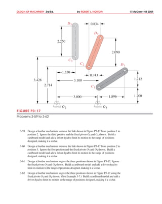
  • 1. DESIGN OF MACHINERY 3rd Ed. by ROBERT L. NORTON © McGraw-Hill 2004 D3 0.834 D2 2.250 2.090 C3 C2 D1 1.350 0.743 3.428 3.100 1.212 2.714 C1 3.000 1.896 1.200 O2 O4 FIGURE P3-17 Problems 3-59 to 3-62 3-59 Design a fourbar mechanism to move the link shown in Figure P3-17 from position 1 to position 2. Ignore the third position and the fixed pivots O2 and O4 shown. Build a cardboard model and add a driver dyad to limit its motion to the range of positions designed, making it a sixbar. 3-60 Design a fourbar mechanism to move the link shown in Figure P3-17 from position 2 to position 3. Ignore the first position and the fixed pivots O2 and O4 shown. Build a cardboard model and add a driver dyad to limit its motion to the range of positions designed, making it a sixbar. 3-61 Design a fourbar mechanism to give the three positions shown in Figure P3-17. Ignore the fixed pivots O2 and O4 shown. Build a cardboard model and add a driver dyad to limit its motion to the range of positions designed, making it a sixbar. 3-62 Design a fourbar mechanism to give the three positions shown in Figure P3-17 using the fixed pivots O2 and O4 shown. (See Example 3-7.) Build a cardboard model and add a driver dyad to limit its motion to the range of positions designed, making it a sixbar.