Fig p3 16
- 1. DESIGN OF MACHINERY 3rd Ed. by ROBERT L. NORTON © McGraw-Hill 2004
7.600 4.500
4.500 4.355
D1 D2
1.134
2.497 C2
C1 1.900
C3 D3 1.000
3.744
5.100
2.900 3.000
O2 O4
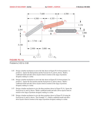
FIGURE P3-16
Problems 3-55 to 3-58
3-55 Design a fourbar mechanism to move the link shown in Figure P3-16 from position 1 to
position 2. Ignore the third position and the fixed pivots O2 and O4 shown. Build a
cardboard model and add a driver dyad to limit its motion to the range of positions
designed, making it a sixbar.
3-56 Design a fourbar mechanism to move the link shown in Figure P3-16 from position 2 to
position 3. Ignore the first position and the fixed pivots O2 and O4 shown. Build a
cardboard model and add a driver dyad to limit its motion to the range of positions
designed, making it a sixbar.
3-57 Design a fourbar mechanism to give the three positions shown in Figure P3-16. Ignore the
fixed pivots O2 and O4 shown. Build a cardboard model and add a driver dyad to limit its
motion to the range of positions designed, making it a sixbar.
3-58 Design a fourbar mechanism to give the three positions shown in Figure P3-16 using the
fixed pivots O2 and O4 shown. (See Example 3-7.) Build a cardboard model and add a
driver dyad to limit its motion to the range of positions designed, making it a sixbar.