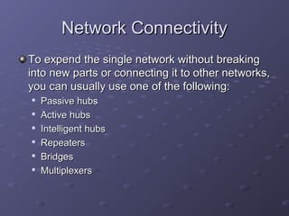
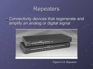
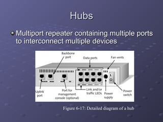
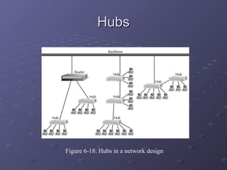
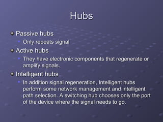
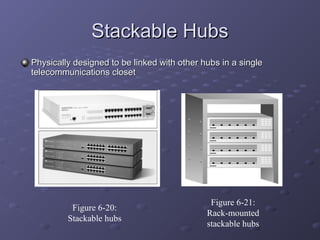
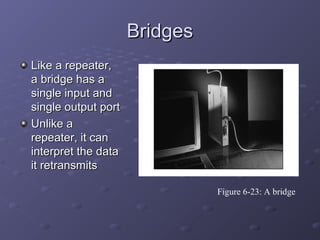
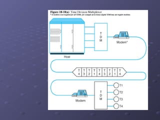
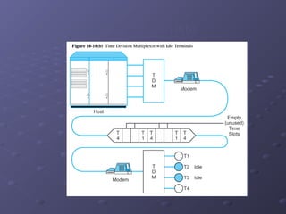
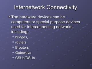
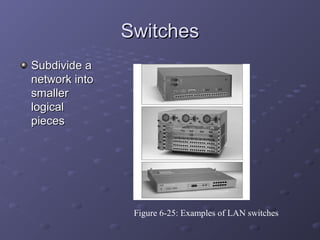
Chapter 10Chapter 10
ExpendingExpending
NetworkingNetworking
Network ConnectivityNetwork Connectivity
To expend the single network without breakingTo expend the single network without breaking
into new parts or connecting it to other networks,into new parts or connecting it to other networks,
you can usually use one of the following:you can usually use one of the following:

Passive hubsPassive hubs

Active hubsActive hubs

Intelligent hubsIntelligent hubs

RepeatersRepeaters

BridgesBridges

MultiplexersMultiplexers
RepeatersRepeaters
Connectivity devices that regenerate andConnectivity devices that regenerate and
amplify an analog or digital signalamplify an analog or digital signal
Figure 6-16: Repeaters
HubsHubs
Multiport repeater containing multiple portsMultiport repeater containing multiple ports
to interconnect multiple devicesto interconnect multiple devices
Figure 6-17: Detailed diagram of a hub
HubsHubs
Elements shared by most hubs:Elements shared by most hubs:

PortsPorts

Uplink portUplink port

Port for management consolePort for management console

Backbone portBackbone port

Link LEDLink LED
HubsHubs
Elements shared by most hubs (cont.):Elements shared by most hubs (cont.):

Traffic (transmit or receive) LEDTraffic (transmit or receive) LED

Collision LED (Ethernet hubs only)Collision LED (Ethernet hubs only)

Power supplyPower supply

Ventilation fanVentilation fan
HubsHubs
Figure 6-18: Hubs in a network design
HubsHubs
Passive hubsPassive hubs

Only repeats signalOnly repeats signal
Active hubsActive hubs

They have electronic components that regenerate orThey have electronic components that regenerate or
amplify signals.amplify signals.
Intelligent hubsIntelligent hubs

In addition signal regeneration, Intelligent hubsIn addition signal regeneration, Intelligent hubs
perform some network management and intelligentperform some network management and intelligent
path selection. A switching hub chooses only the portpath selection. A switching hub chooses only the port
of the device where the signal needs to go.of the device where the signal needs to go.
Stackable HubsStackable Hubs
Physically designed to be linked with other hubs in a singlePhysically designed to be linked with other hubs in a single
telecommunications closettelecommunications closet
Figure 6-20:
Stackable hubs
Figure 6-21:
Rack-mounted
stackable hubs
Installing a HubInstalling a Hub
As with networkAs with network
adapters, theadapters, the
best way tobest way to
ensure a hub isensure a hub is
properly installedproperly installed
is to follow theis to follow the
manufacturer’smanufacturer’s
guidelinesguidelines
Figure 6-22: Connecting a workstation to a hub
Choosing the Right HubChoosing the Right Hub
Factors to consider when selecting theFactors to consider when selecting the
right hub for your network:right hub for your network:

PerformancePerformance

CostCost

Size and growthSize and growth

SecuritySecurity

Management benefitsManagement benefits

ReliabilityReliability
BridgesBridges
Like a repeater,Like a repeater,
a bridge has aa bridge has a
single input andsingle input and
single output portsingle output port
Unlike aUnlike a
repeater, it canrepeater, it can
interpret the datainterpret the data
it retransmitsit retransmits
Figure 6-23: A bridge
BridgesBridges
Spanning tree algorithmSpanning tree algorithm

Routine that can detect circular traffic patterns andRoutine that can detect circular traffic patterns and
modify the way multiple bridges work together, inmodify the way multiple bridges work together, in
order to avoid such patternsorder to avoid such patterns
Transparent bridgingTransparent bridging

Method used on many Ethernet networksMethod used on many Ethernet networks
Source-route bridgingSource-route bridging

Method used on most Token Ring networksMethod used on most Token Ring networks
Translation bridgingTranslation bridging

Method that can use different logical topologiesMethod that can use different logical topologies
MultiplexersMultiplexers
MultiplexingMultiplexing technologies allow multiple signals to betechnologies allow multiple signals to be
transmitted over a single communication link;transmitted over a single communication link; multiplexersmultiplexers
(muxes) allow several devices to share a common circuit(muxes) allow several devices to share a common circuit
Multiplexers combine data from all incoming lines andMultiplexers combine data from all incoming lines and
transmits them via one line to another multiplexer whichtransmits them via one line to another multiplexer which
separates the data and distributes it among outgoing terminalseparates the data and distributes it among outgoing terminal
lineslines
Figure 10-8 illustrates a generic multiplexer configurationFigure 10-8 illustrates a generic multiplexer configuration
To terminal users, the multiplexer appears to function asTo terminal users, the multiplexer appears to function as
though there were several physical lines to the host instead ofthough there were several physical lines to the host instead of
just onejust one
Multiplexers avoid the need to have multiple connectionsMultiplexers avoid the need to have multiple connections
between two locationsbetween two locations
Figure 10-8
Kinds of MultiplexersKinds of Multiplexers
A communication link is divided among severalA communication link is divided among several
users in two basic ways:users in two basic ways:

Frequency division multiplexingFrequency division multiplexing (FDM)(FDM) whichwhich
separates the link’s available bandwidth into sub-separates the link’s available bandwidth into sub-
channels, one for each incoming line (see Figure 10-channels, one for each incoming line (see Figure 10-
9)9)

Time division multiplexing (TDM)Time division multiplexing (TDM) which separates linkwhich separates link
into time slots. Each incoming line is given a time slotinto time slots. Each incoming line is given a time slot
for transmitting a byte (or bit) – see Figure 10-10(a)for transmitting a byte (or bit) – see Figure 10-10(a)
Figure 10-9
Figure 10-10(a)
Statistical TDMStatistical TDM
A major shortcoming of TDM is revealed when attachedA major shortcoming of TDM is revealed when attached
lines do not have data to transmitlines do not have data to transmit

Times slots allocated to idle lines go unused (see Figure 10-10bTimes slots allocated to idle lines go unused (see Figure 10-10b
and Figure 10-11)and Figure 10-11)

Communication circuit is not used to its fullest extent in thisCommunication circuit is not used to its fullest extent in this
circumstancecircumstance
A statistical time division multiplexor (STDM) improvesA statistical time division multiplexor (STDM) improves
on TDM efficiency by transmitting data only for lines withon TDM efficiency by transmitting data only for lines with
data to send by reallocating time slots so that idle linesdata to send by reallocating time slots so that idle lines
take up none of the carrying capacity of thetake up none of the carrying capacity of the
communication circuit (see Figure 10-10c and Figure 10-communication circuit (see Figure 10-10c and Figure 10-
12)12)
Figure 10-10(b)
Figure 10-10(c)
Internetwork ConnectivityInternetwork Connectivity
The hardware devices can beThe hardware devices can be
computers or special purpose devicescomputers or special purpose devices
used for interconnecting networksused for interconnecting networks
including:including:

bridges,bridges,

routersrouters

BroutersBrouters

GatewaysGateways

CSUs/DSUsCSUs/DSUs
SwitchesSwitches
Subdivide aSubdivide a
network intonetwork into
smallersmaller
logicallogical
piecespieces
Figure 6-25: Examples of LAN switches
Cut-Through Mode andCut-Through Mode and
Store and Forward ModeStore and Forward Mode
Cut-through modeCut-through mode

Switching mode in which switch reads a frame’sSwitching mode in which switch reads a frame’s
header and decides where to forward the dataheader and decides where to forward the data
before it receives the entire packetbefore it receives the entire packet

Cut-through switches can detectCut-through switches can detect runtsrunts, or, or
packet fragmentspacket fragments
Store and forward modeStore and forward mode

Switching mode in which switch reads the entireSwitching mode in which switch reads the entire
data frame into its memory and checks it fordata frame into its memory and checks it for
accuracy before transmitting the informationaccuracy before transmitting the information
RoutersRouters
Multiport connectivity deviceMultiport connectivity device
Can integrate LANs and WANs running atCan integrate LANs and WANs running at
different transmission speeds and using adifferent transmission speeds and using a
variety of protocolsvariety of protocols
Routers operate at the Network layerRouters operate at the Network layer
(Layer 3) of the OSI Model(Layer 3) of the OSI Model
Router Features and FunctionsRouter Features and Functions
Modular routerModular router

Router withRouter with
multiple slotsmultiple slots
that can holdthat can hold
differentdifferent
interface cardsinterface cards
or otheror other
devicesdevices
Figure 6-27: Routers
Router Features and FunctionsRouter Features and Functions
Filter out broadcast transmission to alleviate networkFilter out broadcast transmission to alleviate network
congestioncongestion
Prevent certain types of traffic from getting to aPrevent certain types of traffic from getting to a
networknetwork
Support simultaneous local and remote activitySupport simultaneous local and remote activity
Provide high network fault tolerance throughProvide high network fault tolerance through
redundant componentsredundant components
Monitor network traffic and report statistics to a MIBMonitor network traffic and report statistics to a MIB
Diagnose internal or other connectivity problemsDiagnose internal or other connectivity problems
and trigger alarmsand trigger alarms
Router Features and FunctionsRouter Features and Functions
Static routingStatic routing

Technique in which a network administrator programsTechnique in which a network administrator programs
a router to use a specified paths between nodesa router to use a specified paths between nodes
Dynamic routingDynamic routing

Automatically calculates best path between nodesAutomatically calculates best path between nodes
and accumulates this information in a routing tableand accumulates this information in a routing table
HopHop

Term used in networking to describe each trip dataTerm used in networking to describe each trip data
take from one connectivity device to anothertake from one connectivity device to another
Router Features and FunctionsRouter Features and Functions
Figure 6-28: The placement of routers on a LAN
Routing ProtocolsRouting Protocols
The four most common routing protocols:The four most common routing protocols:

RIP (Routing Information Protocol) for IP andRIP (Routing Information Protocol) for IP and
IPXIPX

OSPF (Open Shortest Path First) for IPOSPF (Open Shortest Path First) for IP

EIGRP (Enhanced Interior Gateway RoutingEIGRP (Enhanced Interior Gateway Routing
Protocol) for IP, IPX, and AppleTalkProtocol) for IP, IPX, and AppleTalk

BGP (Border Gateway Protocol) for IPBGP (Border Gateway Protocol) for IP
Brouters and Routing SwitchesBrouters and Routing Switches
Bridge routerBridge router

Also called aAlso called a brouterbrouter

Industry term used to describe routers thatIndustry term used to describe routers that
take on some characteristics of bridgestake on some characteristics of bridges
Routing switchRouting switch

Router hybrid that combines a router and aRouter hybrid that combines a router and a
switchswitch
GatewaysGateways
Combination of networking hardware andCombination of networking hardware and
software that connects two dissimilar kinds ofsoftware that connects two dissimilar kinds of
networksnetworks
Popular types of gateways include:Popular types of gateways include:

E-mail gatewaysE-mail gateways

IBM host gatewaysIBM host gateways

Internet gatewaysInternet gateways

LAN gatewaysLAN gateways
CSUs/DSUsCSUs/DSUs
Channel Service Units/Digital ServiceChannel Service Units/Digital Service
Units (CSUs/DSUs): NetworkUnits (CSUs/DSUs): Network
interconnectivity devices that connect ainterconnectivity devices that connect a
network to the public telephone network.network to the public telephone network.
CSUs/DSUs translate signals and shieldCSUs/DSUs translate signals and shield
networks from noise and high voltage onnetworks from noise and high voltage on
the public netwrok.the public netwrok.

Expending Networking

  • 1.
  • 2.
    Network ConnectivityNetwork Connectivity Toexpend the single network without breakingTo expend the single network without breaking into new parts or connecting it to other networks,into new parts or connecting it to other networks, you can usually use one of the following:you can usually use one of the following:  Passive hubsPassive hubs  Active hubsActive hubs  Intelligent hubsIntelligent hubs  RepeatersRepeaters  BridgesBridges  MultiplexersMultiplexers
  • 3.
    RepeatersRepeaters Connectivity devices thatregenerate andConnectivity devices that regenerate and amplify an analog or digital signalamplify an analog or digital signal Figure 6-16: Repeaters
  • 4.
    HubsHubs Multiport repeater containingmultiple portsMultiport repeater containing multiple ports to interconnect multiple devicesto interconnect multiple devices Figure 6-17: Detailed diagram of a hub
  • 5.
    HubsHubs Elements shared bymost hubs:Elements shared by most hubs:  PortsPorts  Uplink portUplink port  Port for management consolePort for management console  Backbone portBackbone port  Link LEDLink LED
  • 6.
    HubsHubs Elements shared bymost hubs (cont.):Elements shared by most hubs (cont.):  Traffic (transmit or receive) LEDTraffic (transmit or receive) LED  Collision LED (Ethernet hubs only)Collision LED (Ethernet hubs only)  Power supplyPower supply  Ventilation fanVentilation fan
  • 7.
    HubsHubs Figure 6-18: Hubsin a network design
  • 8.
    HubsHubs Passive hubsPassive hubs  Onlyrepeats signalOnly repeats signal Active hubsActive hubs  They have electronic components that regenerate orThey have electronic components that regenerate or amplify signals.amplify signals. Intelligent hubsIntelligent hubs  In addition signal regeneration, Intelligent hubsIn addition signal regeneration, Intelligent hubs perform some network management and intelligentperform some network management and intelligent path selection. A switching hub chooses only the portpath selection. A switching hub chooses only the port of the device where the signal needs to go.of the device where the signal needs to go.
  • 9.
    Stackable HubsStackable Hubs Physicallydesigned to be linked with other hubs in a singlePhysically designed to be linked with other hubs in a single telecommunications closettelecommunications closet Figure 6-20: Stackable hubs Figure 6-21: Rack-mounted stackable hubs
  • 10.
    Installing a HubInstallinga Hub As with networkAs with network adapters, theadapters, the best way tobest way to ensure a hub isensure a hub is properly installedproperly installed is to follow theis to follow the manufacturer’smanufacturer’s guidelinesguidelines Figure 6-22: Connecting a workstation to a hub
  • 11.
    Choosing the RightHubChoosing the Right Hub Factors to consider when selecting theFactors to consider when selecting the right hub for your network:right hub for your network:  PerformancePerformance  CostCost  Size and growthSize and growth  SecuritySecurity  Management benefitsManagement benefits  ReliabilityReliability
  • 12.
    BridgesBridges Like a repeater,Likea repeater, a bridge has aa bridge has a single input andsingle input and single output portsingle output port Unlike aUnlike a repeater, it canrepeater, it can interpret the datainterpret the data it retransmitsit retransmits Figure 6-23: A bridge
  • 13.
    BridgesBridges Spanning tree algorithmSpanningtree algorithm  Routine that can detect circular traffic patterns andRoutine that can detect circular traffic patterns and modify the way multiple bridges work together, inmodify the way multiple bridges work together, in order to avoid such patternsorder to avoid such patterns Transparent bridgingTransparent bridging  Method used on many Ethernet networksMethod used on many Ethernet networks Source-route bridgingSource-route bridging  Method used on most Token Ring networksMethod used on most Token Ring networks Translation bridgingTranslation bridging  Method that can use different logical topologiesMethod that can use different logical topologies
  • 14.
    MultiplexersMultiplexers MultiplexingMultiplexing technologies allowmultiple signals to betechnologies allow multiple signals to be transmitted over a single communication link;transmitted over a single communication link; multiplexersmultiplexers (muxes) allow several devices to share a common circuit(muxes) allow several devices to share a common circuit Multiplexers combine data from all incoming lines andMultiplexers combine data from all incoming lines and transmits them via one line to another multiplexer whichtransmits them via one line to another multiplexer which separates the data and distributes it among outgoing terminalseparates the data and distributes it among outgoing terminal lineslines Figure 10-8 illustrates a generic multiplexer configurationFigure 10-8 illustrates a generic multiplexer configuration To terminal users, the multiplexer appears to function asTo terminal users, the multiplexer appears to function as though there were several physical lines to the host instead ofthough there were several physical lines to the host instead of just onejust one Multiplexers avoid the need to have multiple connectionsMultiplexers avoid the need to have multiple connections between two locationsbetween two locations
  • 15.
  • 16.
    Kinds of MultiplexersKindsof Multiplexers A communication link is divided among severalA communication link is divided among several users in two basic ways:users in two basic ways:  Frequency division multiplexingFrequency division multiplexing (FDM)(FDM) whichwhich separates the link’s available bandwidth into sub-separates the link’s available bandwidth into sub- channels, one for each incoming line (see Figure 10-channels, one for each incoming line (see Figure 10- 9)9)  Time division multiplexing (TDM)Time division multiplexing (TDM) which separates linkwhich separates link into time slots. Each incoming line is given a time slotinto time slots. Each incoming line is given a time slot for transmitting a byte (or bit) – see Figure 10-10(a)for transmitting a byte (or bit) – see Figure 10-10(a)
  • 17.
  • 18.
  • 19.
    Statistical TDMStatistical TDM Amajor shortcoming of TDM is revealed when attachedA major shortcoming of TDM is revealed when attached lines do not have data to transmitlines do not have data to transmit  Times slots allocated to idle lines go unused (see Figure 10-10bTimes slots allocated to idle lines go unused (see Figure 10-10b and Figure 10-11)and Figure 10-11)  Communication circuit is not used to its fullest extent in thisCommunication circuit is not used to its fullest extent in this circumstancecircumstance A statistical time division multiplexor (STDM) improvesA statistical time division multiplexor (STDM) improves on TDM efficiency by transmitting data only for lines withon TDM efficiency by transmitting data only for lines with data to send by reallocating time slots so that idle linesdata to send by reallocating time slots so that idle lines take up none of the carrying capacity of thetake up none of the carrying capacity of the communication circuit (see Figure 10-10c and Figure 10-communication circuit (see Figure 10-10c and Figure 10- 12)12)
  • 20.
  • 21.
  • 22.
    Internetwork ConnectivityInternetwork Connectivity Thehardware devices can beThe hardware devices can be computers or special purpose devicescomputers or special purpose devices used for interconnecting networksused for interconnecting networks including:including:  bridges,bridges,  routersrouters  BroutersBrouters  GatewaysGateways  CSUs/DSUsCSUs/DSUs
  • 23.
    SwitchesSwitches Subdivide aSubdivide a networkintonetwork into smallersmaller logicallogical piecespieces Figure 6-25: Examples of LAN switches
  • 24.
    Cut-Through Mode andCut-ThroughMode and Store and Forward ModeStore and Forward Mode Cut-through modeCut-through mode  Switching mode in which switch reads a frame’sSwitching mode in which switch reads a frame’s header and decides where to forward the dataheader and decides where to forward the data before it receives the entire packetbefore it receives the entire packet  Cut-through switches can detectCut-through switches can detect runtsrunts, or, or packet fragmentspacket fragments Store and forward modeStore and forward mode  Switching mode in which switch reads the entireSwitching mode in which switch reads the entire data frame into its memory and checks it fordata frame into its memory and checks it for accuracy before transmitting the informationaccuracy before transmitting the information
  • 25.
    RoutersRouters Multiport connectivity deviceMultiportconnectivity device Can integrate LANs and WANs running atCan integrate LANs and WANs running at different transmission speeds and using adifferent transmission speeds and using a variety of protocolsvariety of protocols Routers operate at the Network layerRouters operate at the Network layer (Layer 3) of the OSI Model(Layer 3) of the OSI Model
  • 26.
    Router Features andFunctionsRouter Features and Functions Modular routerModular router  Router withRouter with multiple slotsmultiple slots that can holdthat can hold differentdifferent interface cardsinterface cards or otheror other devicesdevices Figure 6-27: Routers
  • 27.
    Router Features andFunctionsRouter Features and Functions Filter out broadcast transmission to alleviate networkFilter out broadcast transmission to alleviate network congestioncongestion Prevent certain types of traffic from getting to aPrevent certain types of traffic from getting to a networknetwork Support simultaneous local and remote activitySupport simultaneous local and remote activity Provide high network fault tolerance throughProvide high network fault tolerance through redundant componentsredundant components Monitor network traffic and report statistics to a MIBMonitor network traffic and report statistics to a MIB Diagnose internal or other connectivity problemsDiagnose internal or other connectivity problems and trigger alarmsand trigger alarms
  • 28.
    Router Features andFunctionsRouter Features and Functions Static routingStatic routing  Technique in which a network administrator programsTechnique in which a network administrator programs a router to use a specified paths between nodesa router to use a specified paths between nodes Dynamic routingDynamic routing  Automatically calculates best path between nodesAutomatically calculates best path between nodes and accumulates this information in a routing tableand accumulates this information in a routing table HopHop  Term used in networking to describe each trip dataTerm used in networking to describe each trip data take from one connectivity device to anothertake from one connectivity device to another
  • 29.
    Router Features andFunctionsRouter Features and Functions Figure 6-28: The placement of routers on a LAN
  • 30.
    Routing ProtocolsRouting Protocols Thefour most common routing protocols:The four most common routing protocols:  RIP (Routing Information Protocol) for IP andRIP (Routing Information Protocol) for IP and IPXIPX  OSPF (Open Shortest Path First) for IPOSPF (Open Shortest Path First) for IP  EIGRP (Enhanced Interior Gateway RoutingEIGRP (Enhanced Interior Gateway Routing Protocol) for IP, IPX, and AppleTalkProtocol) for IP, IPX, and AppleTalk  BGP (Border Gateway Protocol) for IPBGP (Border Gateway Protocol) for IP
  • 31.
    Brouters and RoutingSwitchesBrouters and Routing Switches Bridge routerBridge router  Also called aAlso called a brouterbrouter  Industry term used to describe routers thatIndustry term used to describe routers that take on some characteristics of bridgestake on some characteristics of bridges Routing switchRouting switch  Router hybrid that combines a router and aRouter hybrid that combines a router and a switchswitch
  • 32.
    GatewaysGateways Combination of networkinghardware andCombination of networking hardware and software that connects two dissimilar kinds ofsoftware that connects two dissimilar kinds of networksnetworks Popular types of gateways include:Popular types of gateways include:  E-mail gatewaysE-mail gateways  IBM host gatewaysIBM host gateways  Internet gatewaysInternet gateways  LAN gatewaysLAN gateways
  • 33.
    CSUs/DSUsCSUs/DSUs Channel Service Units/DigitalServiceChannel Service Units/Digital Service Units (CSUs/DSUs): NetworkUnits (CSUs/DSUs): Network interconnectivity devices that connect ainterconnectivity devices that connect a network to the public telephone network.network to the public telephone network. CSUs/DSUs translate signals and shieldCSUs/DSUs translate signals and shield networks from noise and high voltage onnetworks from noise and high voltage on the public netwrok.the public netwrok.