Introduction
As organizationgrow in size, network also grow and
performance decreases.
Sometime necessary to break or segment a local area
network into smaller, multiple segments, and some
type of interconnection among segment is required to
access wide range of resources.
Interconnecting multiple networks or multiple
segments of networks is called internetworking.
Breaking a large network into smaller networks is
called segmentation.
3.
Why segment orInternetwork?
To separate / connect one corporate division
with another.
Improve performance
To provide a security wall between two
different types of users.
Communication between different types of
networks.
4.
Connecting Devices/ NetworkDevices
Most common features of network devices are
to interconnect networks, boost signals etc.
Commonly used devices are:
Repeater
Hub
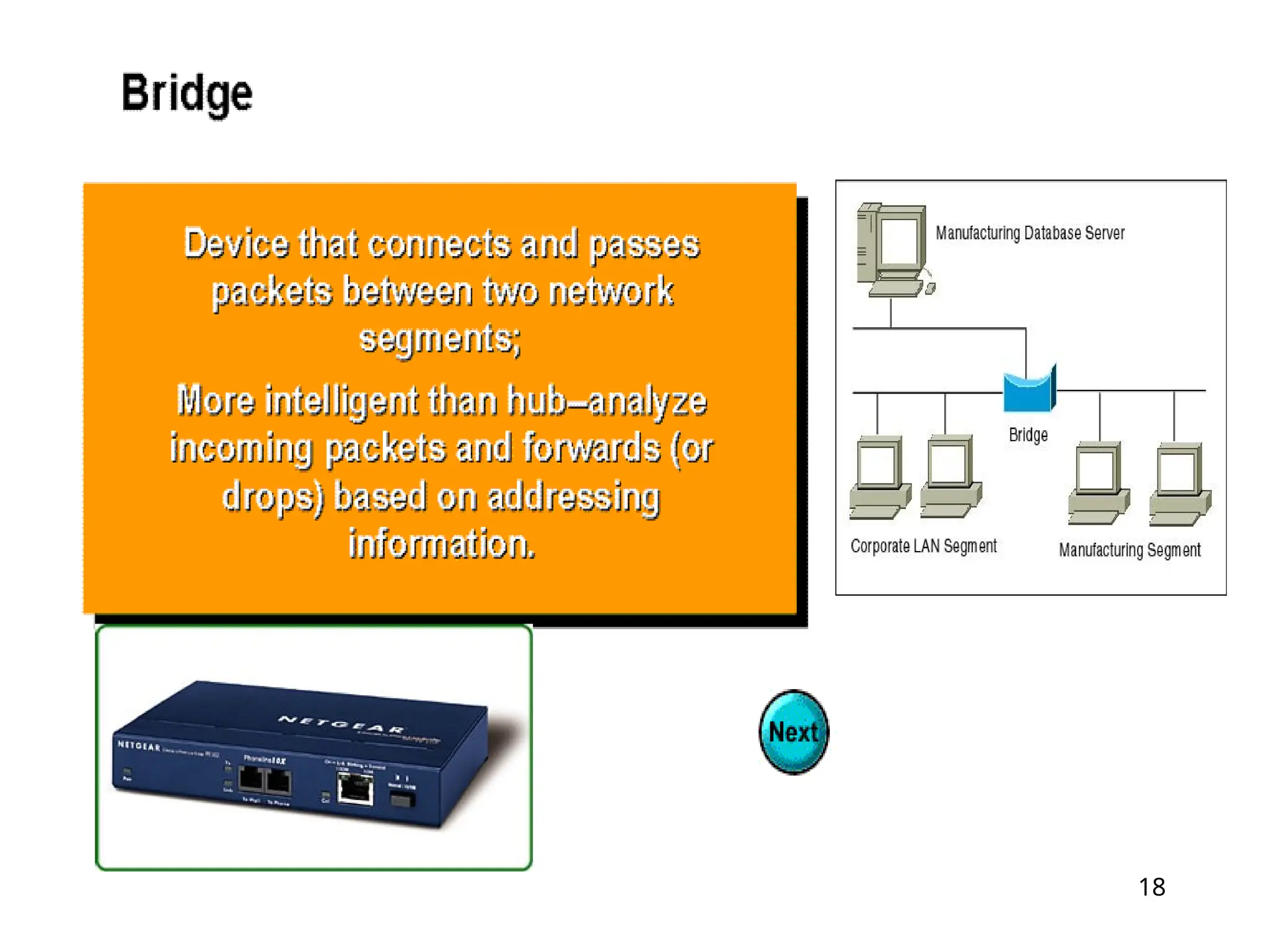
Bridge
Switch
Router
5.
5
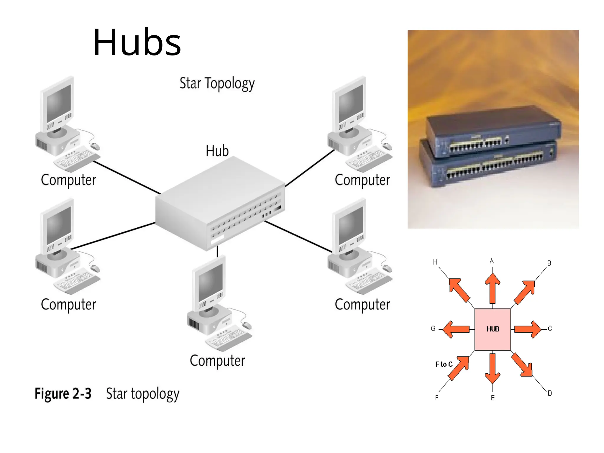
Hubs
A hub interconnectstwo or more workstations into a local
area network.
Hub is a place of convergence where data arrives from
one or more directions and is forwarded out in one or more
other directions.
When a workstation transmits to a hub, the hub
immediately resends the data frame to all connecting links.
Physical layer. Hubs are classified as Layer 1 devices per
the OSI model.
Hubs expand one Ethernet connection into many. For
example, a four-port hub connects up to four machines.
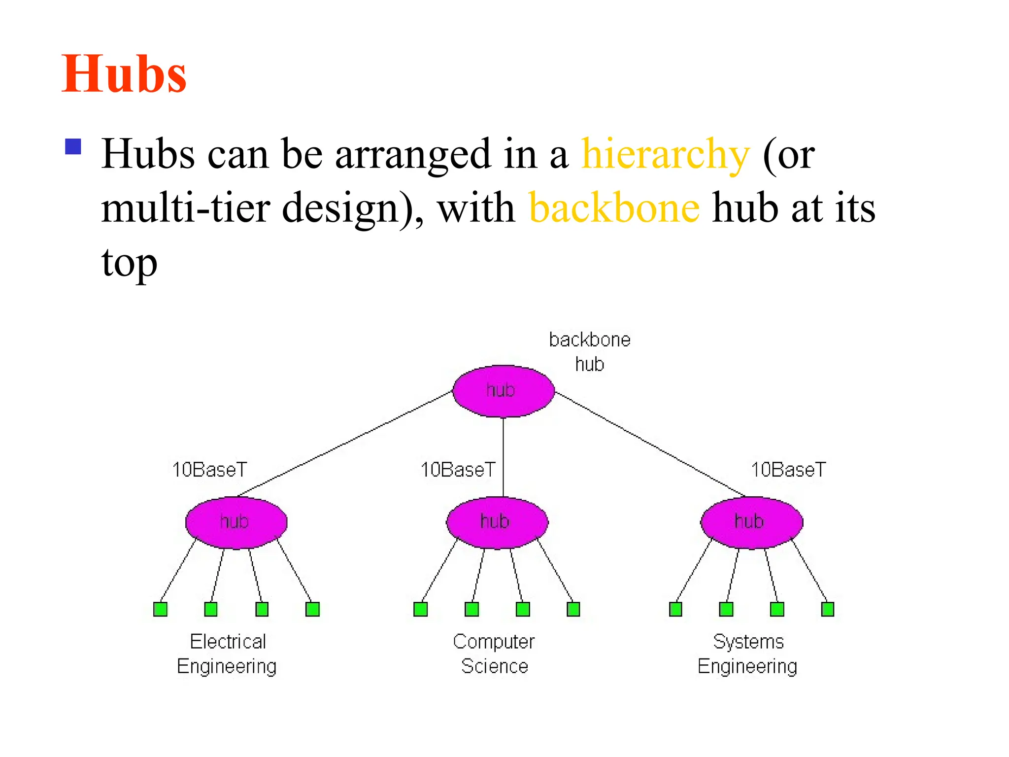
Hubs
Hubs canbe arranged in a hierarchy (or
multi-tier design), with backbone hub at its
top
8.
8
Types of Hub
Thereare many types of hubs with various
features/specifications, which provide the type of
functionality you need in building a network.
On the basis of its working methods, the Hubs can
be divided into three types, given as:
Active Hub
Passive Hub
Intelligent Hub
9.
9
Passive Hub
As thename suggests, passive hubs are the ones,
which do not provide any additional feature except for
working just as an interface between the topology.(Just
a connector.)
These types do not help in rectifying/enhancing the
signals they pass on in the network, in other terms, they
do not help in enhancing the performance of the
network/LAN.
It simply receives signal(s) on input port(s) and
broadcasts it (them) on the output port(s) without even
rectifying it (them).
10.
10
Active Hub
As itsname suggests, Active Hub is a hub which can
amplify or regenerate the information signal. This type
of bus has an advantage as it also amplifies the
incoming signal as well as forward it to multiple
devices.
active hub takes active participation in data
communication within the network/LAN.
receives the frame from an incoming link, regenerates
it, and sends it to all outgoing links.
Active hubs also help in troubleshooting at a certain
level
11.
11
Intelligent Hubs
They addsome more features to that provided by the
active hubs.
It provides all the features of a passive and an active hub;
it also provides some features, which help in managing the
network resources effectively and efficiently.
They help in improving the performance of the
network/LAN that you are using.
As an active hub helps in finding out where the problem
persists, an intelligent hub itself finds out the problem in
the network, diagnoses it and tries to rectify it without
letting the problem hamper the performance of the
network.
12.
12
Contd. Intelligent Hubs
Theyprovide a feature that helps in determining the
exact cause and exact place of the fault.
Another feature of the intelligent hub is that they can
decide which packet goes in which output line, this
helps in controlling and minimizing data traffic in the
network, which results in improved performance of the
network/LAN.
They also help in managing the data communication
within the network, it recognizes the slower devices
automatically and helps them to transmit the data with
their own speed, and during this time, the hub manages
the traffic within the network effectively.
13.
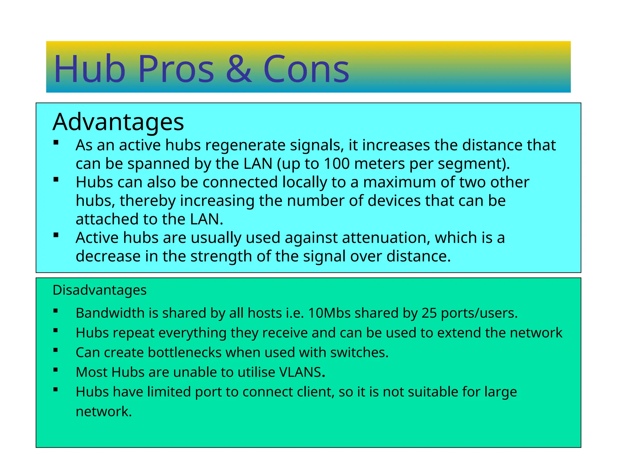
Hub Pros &Cons
Disadvantages
Bandwidth is shared by all hosts i.e. 10Mbs shared by 25 ports/users.
Hubs repeat everything they receive and can be used to extend the network
Can create bottlenecks when used with switches.
Most Hubs are unable to utilise VLANS.
Hubs have limited port to connect client, so it is not suitable for large
network.
Advantages
As an active hubs regenerate signals, it increases the distance that
can be spanned by the LAN (up to 100 meters per segment).
Hubs can also be connected locally to a maximum of two other
hubs, thereby increasing the number of devices that can be
attached to the LAN.
Active hubs are usually used against attenuation, which is a
decrease in the strength of the signal over distance.
14.
14
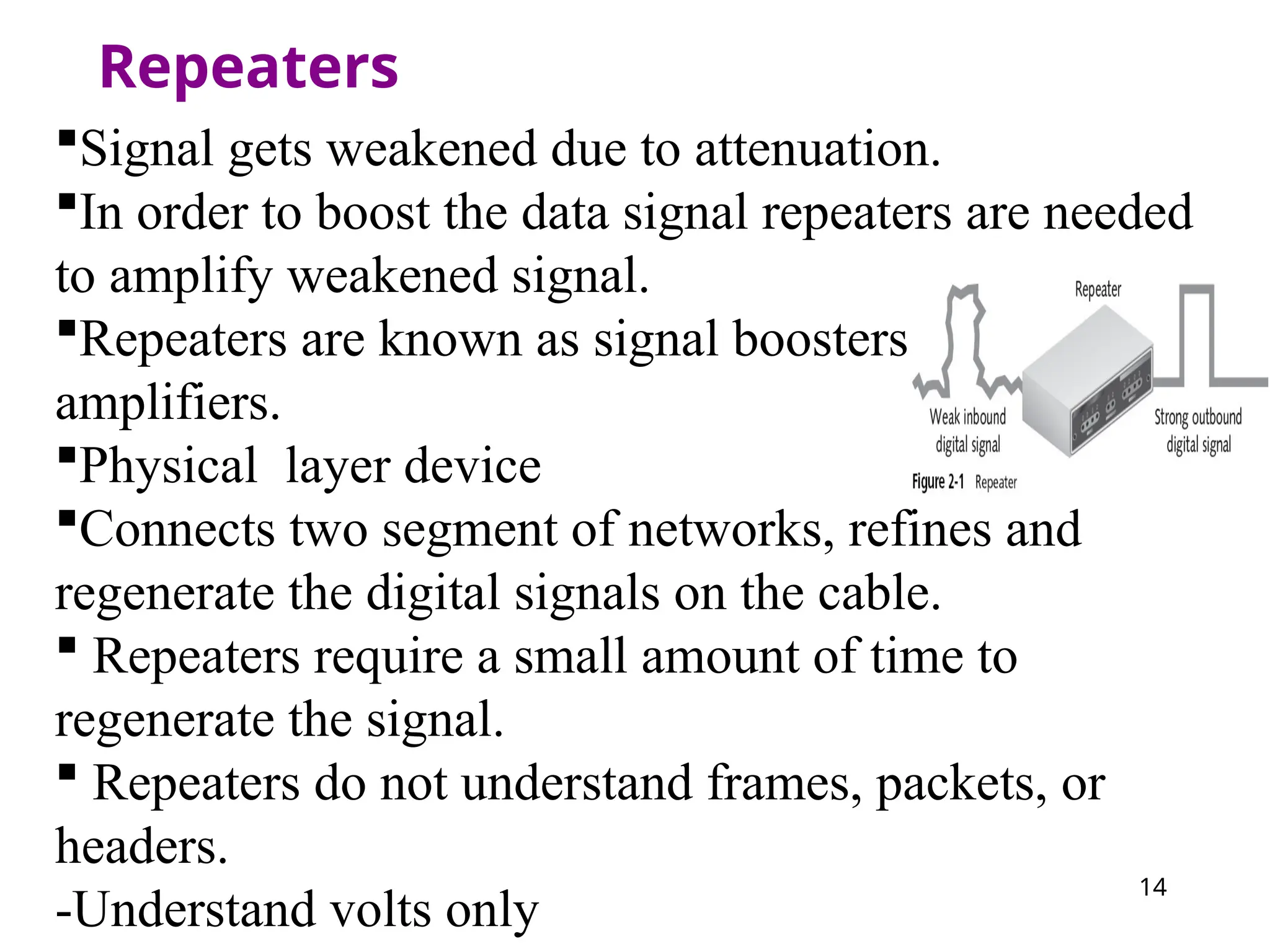
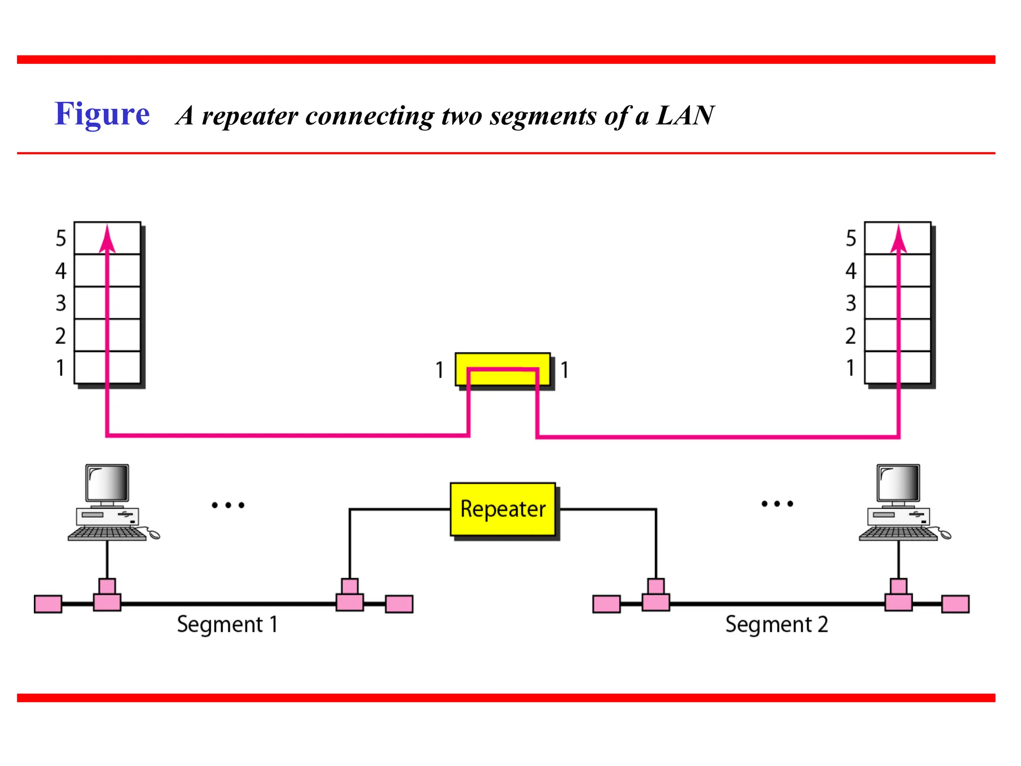
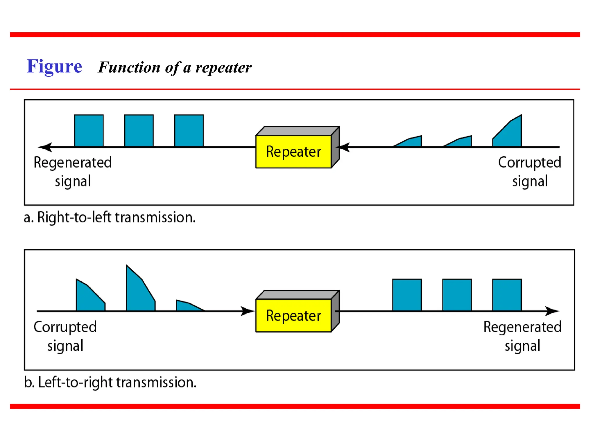
Repeaters
Signal gets weakeneddue to attenuation.
In order to boost the data signal repeaters are needed
to amplify weakened signal.
Repeaters are known as signal boosters are
amplifiers.
Physical layer device
Connects two segment of networks, refines and
regenerate the digital signals on the cable.
Repeaters require a small amount of time to
regenerate the signal.
Repeaters do not understand frames, packets, or
headers.
-Understand volts only
Advantages & Disadvantagesof
using Repeaters
Advantages
Repeaters can extend a network’s total distance.
Repeaters do not seriously impact network performance
Certain repeaters can connect network using different
physical media.([ex. fiber optic, UTF, coaxial cable] is
possible.
Disadvantages
Can not connect different network architecture
Do not reduce network traffic.
19
Contd.
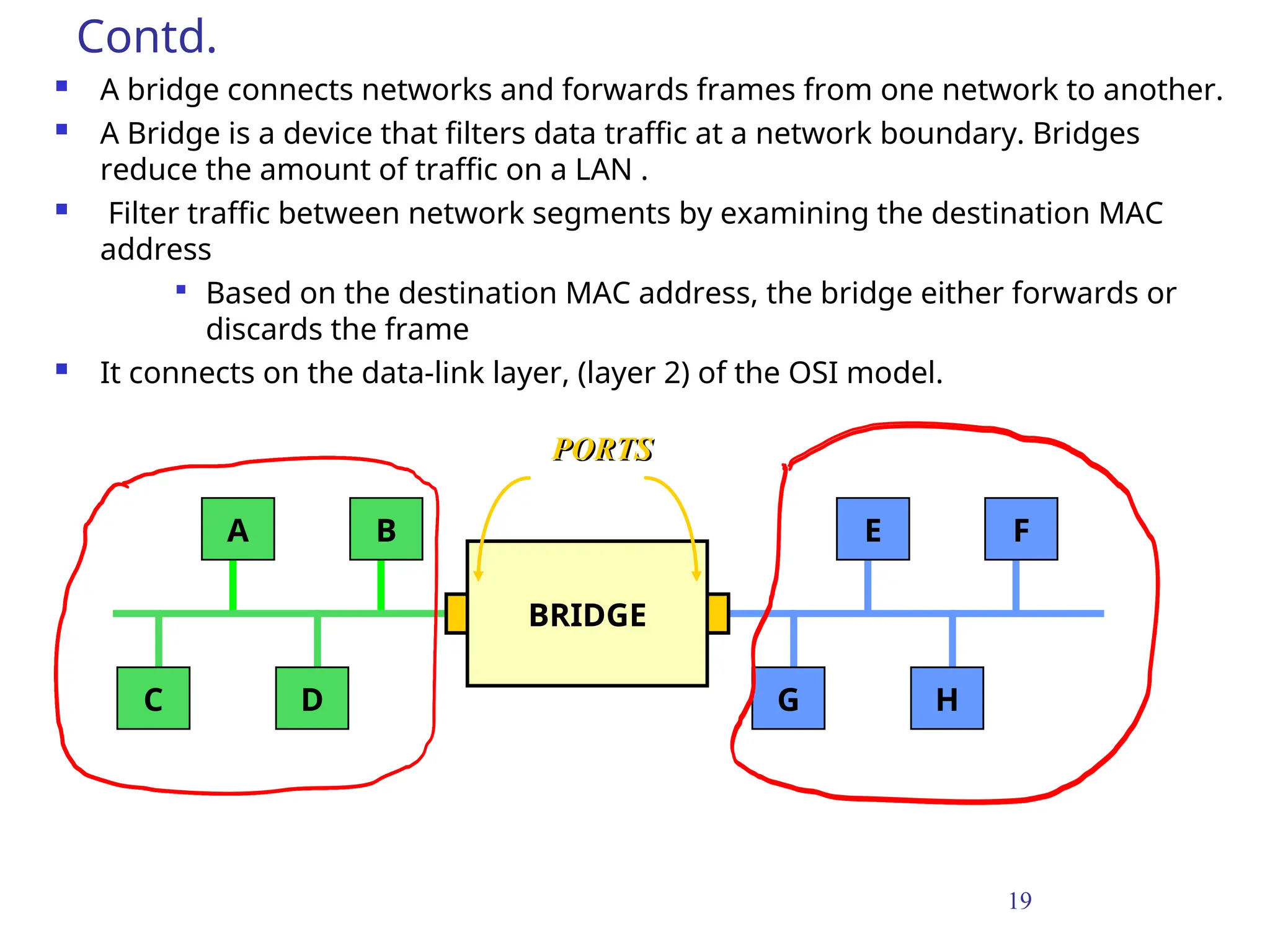
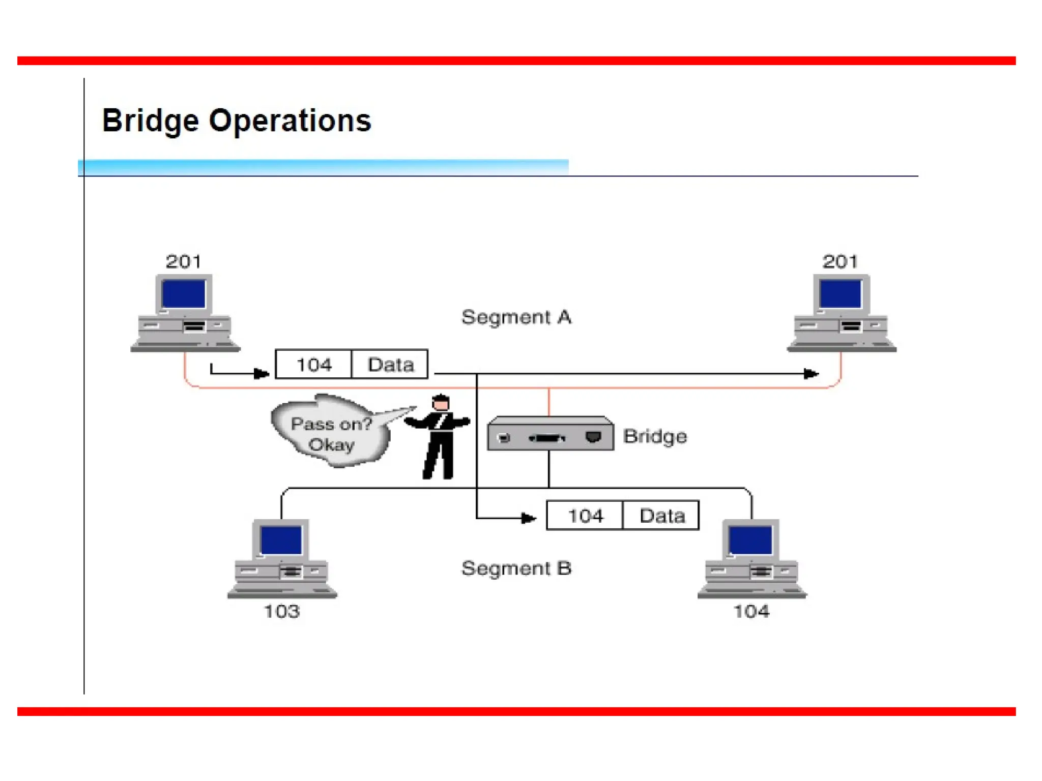
A bridgeconnects networks and forwards frames from one network to another.
A Bridge is a device that filters data traffic at a network boundary. Bridges
reduce the amount of traffic on a LAN .
Filter traffic between network segments by examining the destination MAC
address
Based on the destination MAC address, the bridge either forwards or
discards the frame
It connects on the data-link layer, (layer 2) of the OSI model.
A B
C D
E F
G H
BRIDGE
PORTS
20.
20
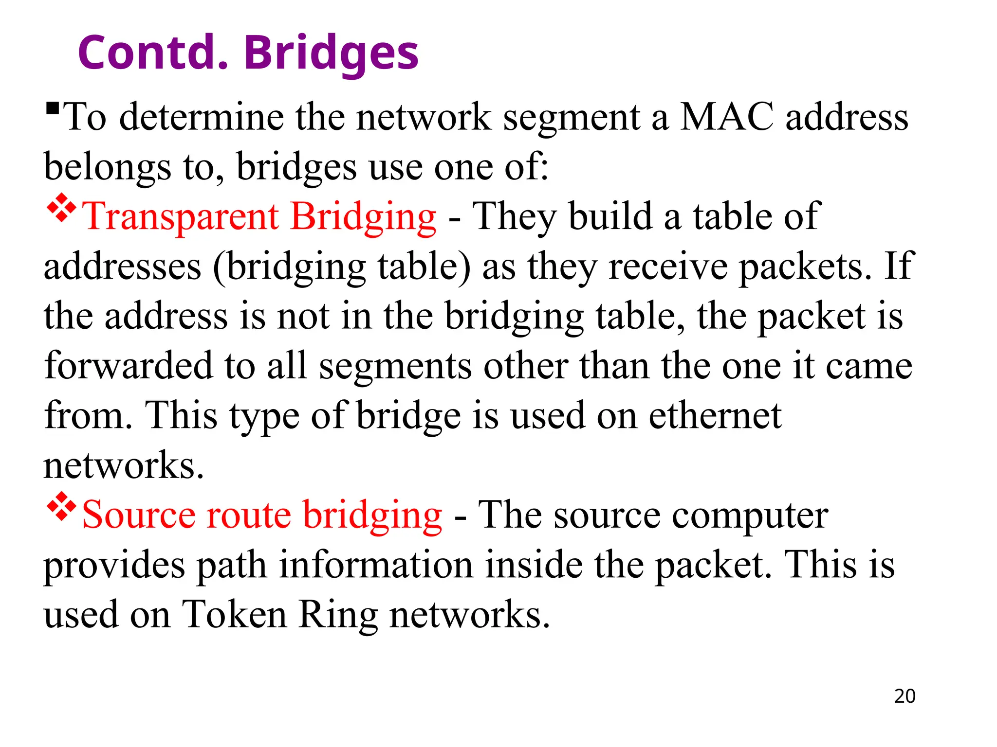
Contd. Bridges
To determinethe network segment a MAC address
belongs to, bridges use one of:
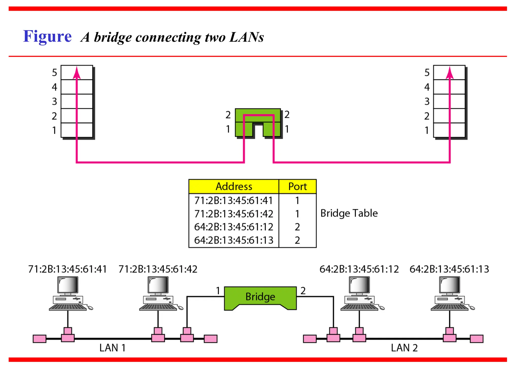
Transparent Bridging - They build a table of
addresses (bridging table) as they receive packets. If
the address is not in the bridging table, the packet is
forwarded to all segments other than the one it came
from. This type of bridge is used on ethernet
networks.
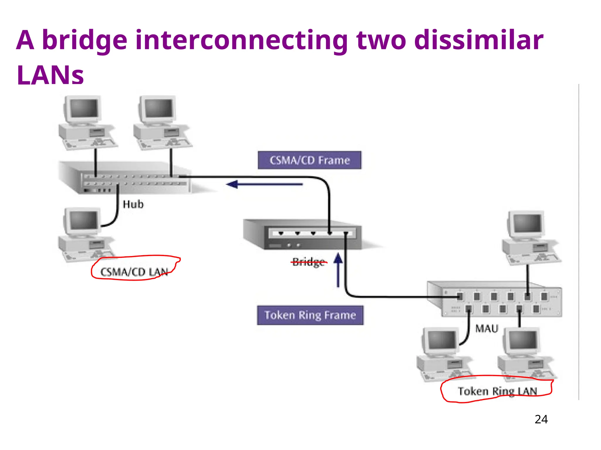
Source route bridging - The source computer
provides path information inside the packet. This is
used on Token Ring networks.
25
Advantages and Disadvantagesof
Bridges
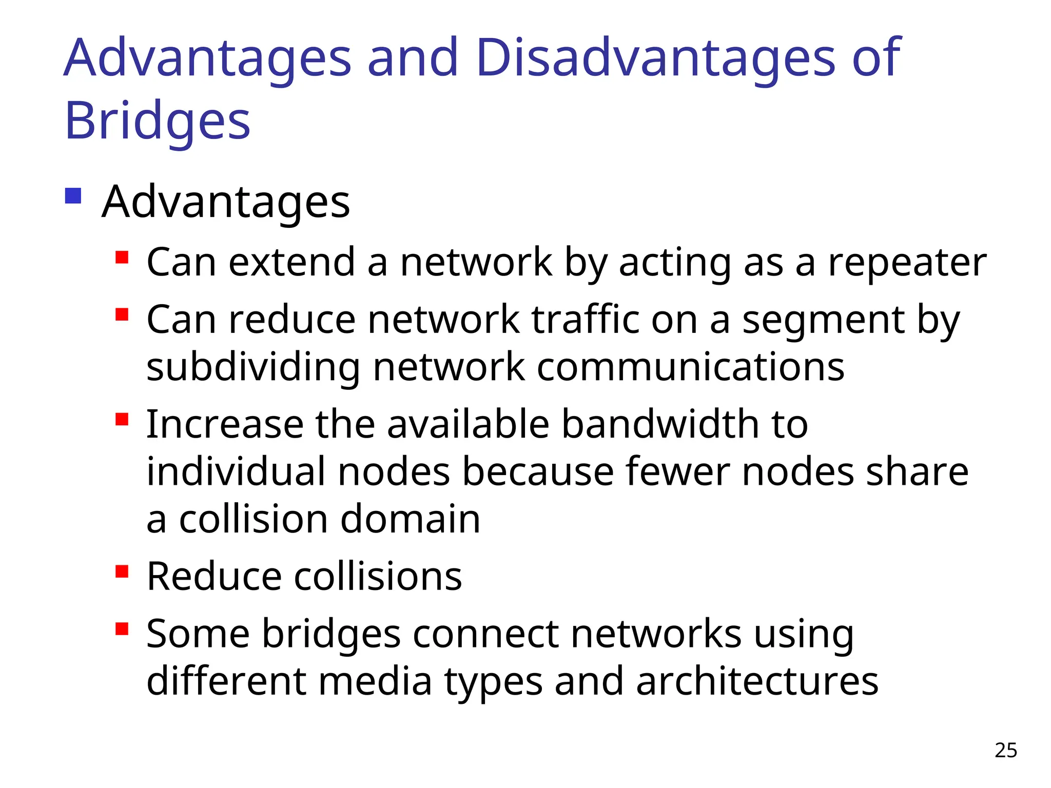
Advantages
Can extend a network by acting as a repeater
Can reduce network traffic on a segment by
subdividing network communications
Increase the available bandwidth to
individual nodes because fewer nodes share
a collision domain
Reduce collisions
Some bridges connect networks using
different media types and architectures
26.
26
Advantages and Disadvantagesof
Bridges (continued)
Disadvantages
Slower than repeaters and hubs
Extra processing by viewing MAC addresses
Forward broadcast frames indiscriminately,
so they do not filter broadcast traffic
More expensive than repeaters and hubs
Broadcast storm
When two or more stations engage in the
transmission of excessive broadcast traffic
27.
27
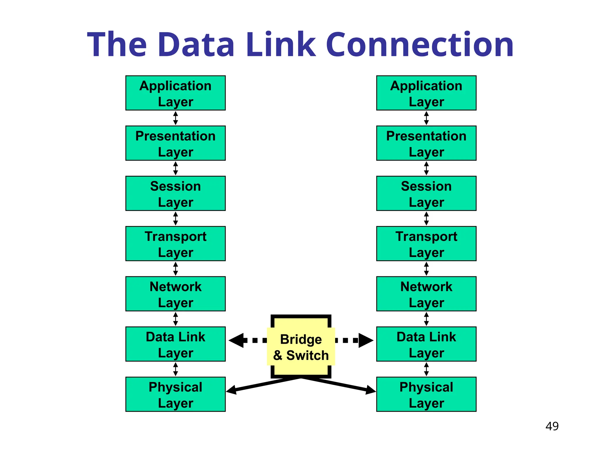
Cisco Catalyst 2900switch
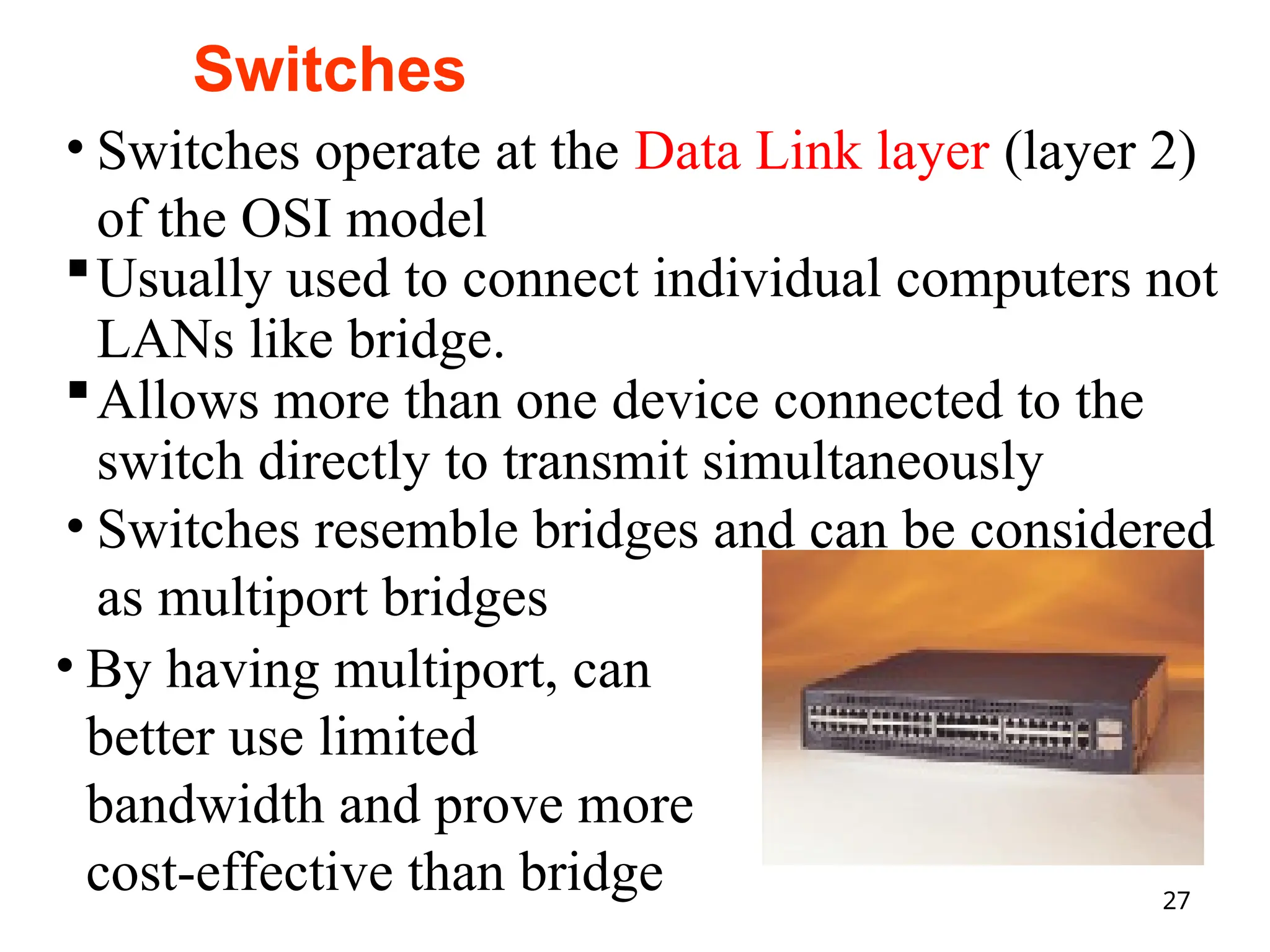
• Switches operate at the Data Link layer (layer 2)
of the OSI model
Usually used to connect individual computers not
LANs like bridge.
Allows more than one device connected to the
switch directly to transmit simultaneously
• Switches resemble bridges and can be considered
as multiport bridges
• By having multiport, can
better use limited
bandwidth and prove more
cost-effective than bridge
Switches
28.
28
Contd. Switches
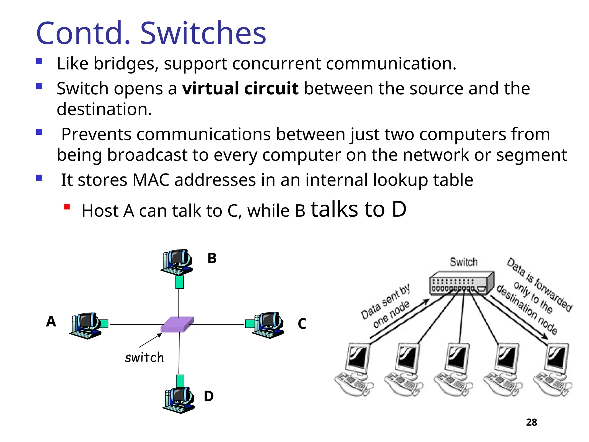
Likebridges, support concurrent communication.
Switch opens a virtual circuit between the source and the
destination.
Prevents communications between just two computers from
being broadcast to every computer on the network or segment
It stores MAC addresses in an internal lookup table
Host A can talk to C, while B talks to D
switch
A
B
C
D
30
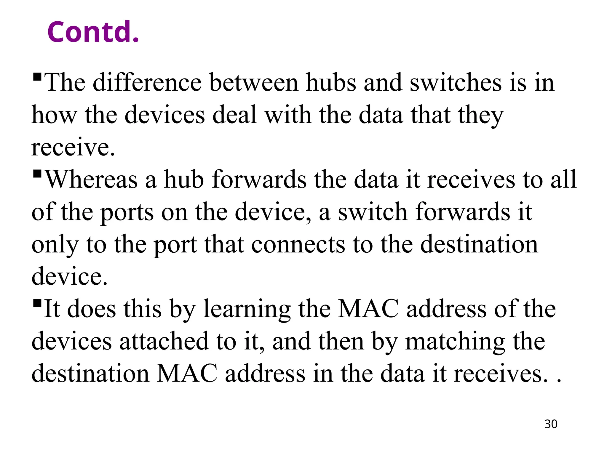
Contd.
The difference betweenhubs and switches is in
how the devices deal with the data that they
receive.
Whereas a hub forwards the data it receives to all
of the ports on the device, a switch forwards it
only to the port that connects to the destination
device.
It does this by learning the MAC address of the
devices attached to it, and then by matching the
destination MAC address in the data it receives. .
31.
31
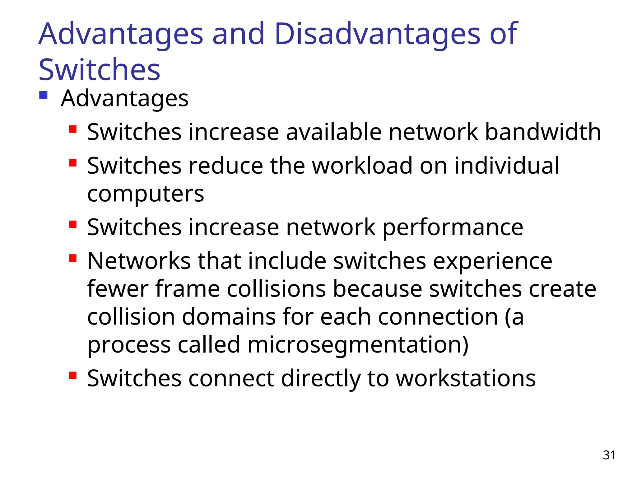
Advantages and Disadvantagesof
Switches
Advantages
Switches increase available network bandwidth
Switches reduce the workload on individual
computers
Switches increase network performance
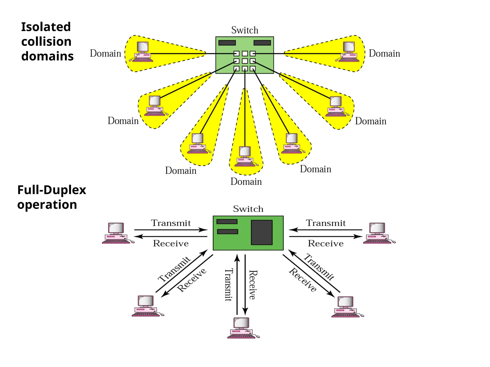
Networks that include switches experience
fewer frame collisions because switches create
collision domains for each connection (a
process called microsegmentation)
Switches connect directly to workstations
32.
32
Advantages and
Disadvantages ofSwitches
(continued)
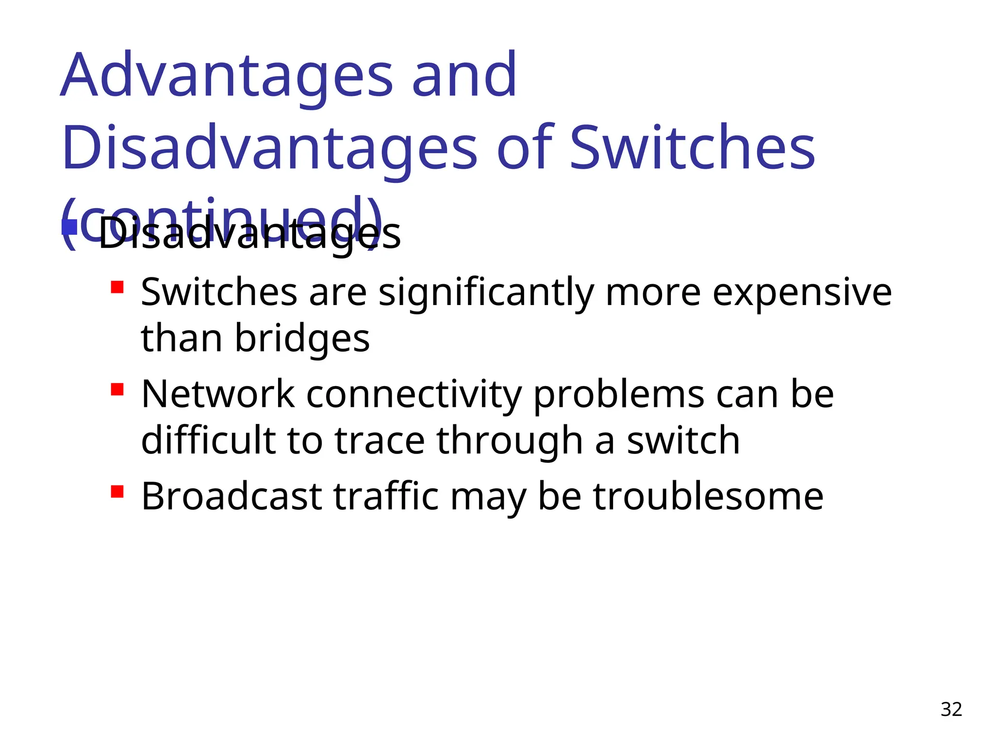
Disadvantages
Switches are significantly more expensive
than bridges
Network connectivity problems can be
difficult to trace through a switch
Broadcast traffic may be troublesome
33.
33
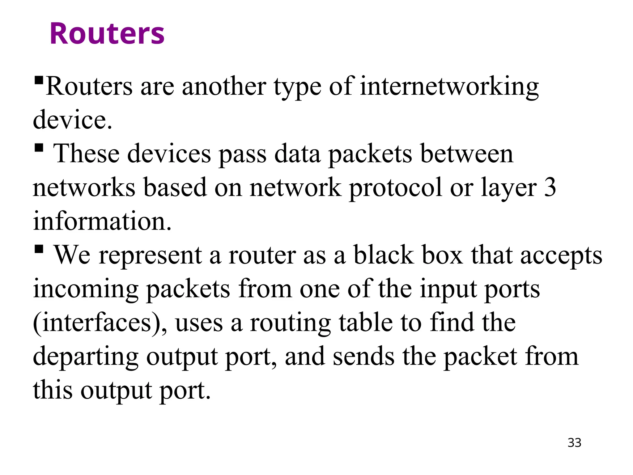
Routers
Routers are anothertype of internetworking
device.
These devices pass data packets between
networks based on network protocol or layer 3
information.
We represent a router as a black box that accepts
incoming packets from one of the input ports
(interfaces), uses a routing table to find the
departing output port, and sends the packet from
this output port.
34.
34
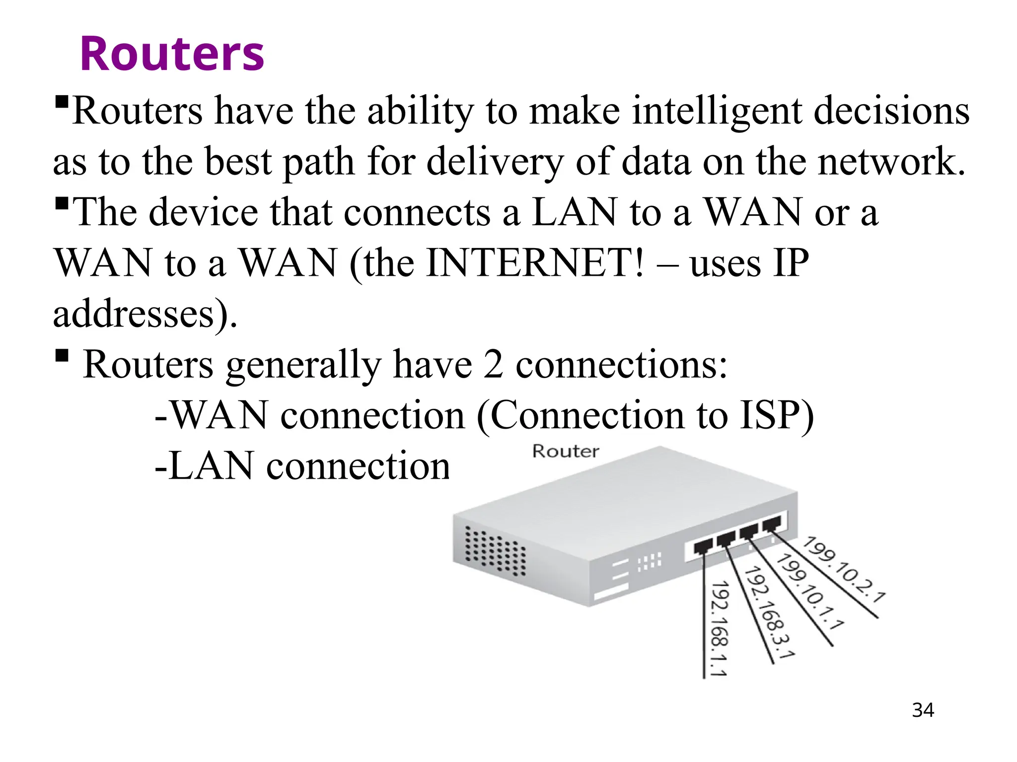
Routers
Routers have theability to make intelligent decisions
as to the best path for delivery of data on the network.
The device that connects a LAN to a WAN or a
WAN to a WAN (the INTERNET! – uses IP
addresses).
Routers generally have 2 connections:
-WAN connection (Connection to ISP)
-LAN connection
35.
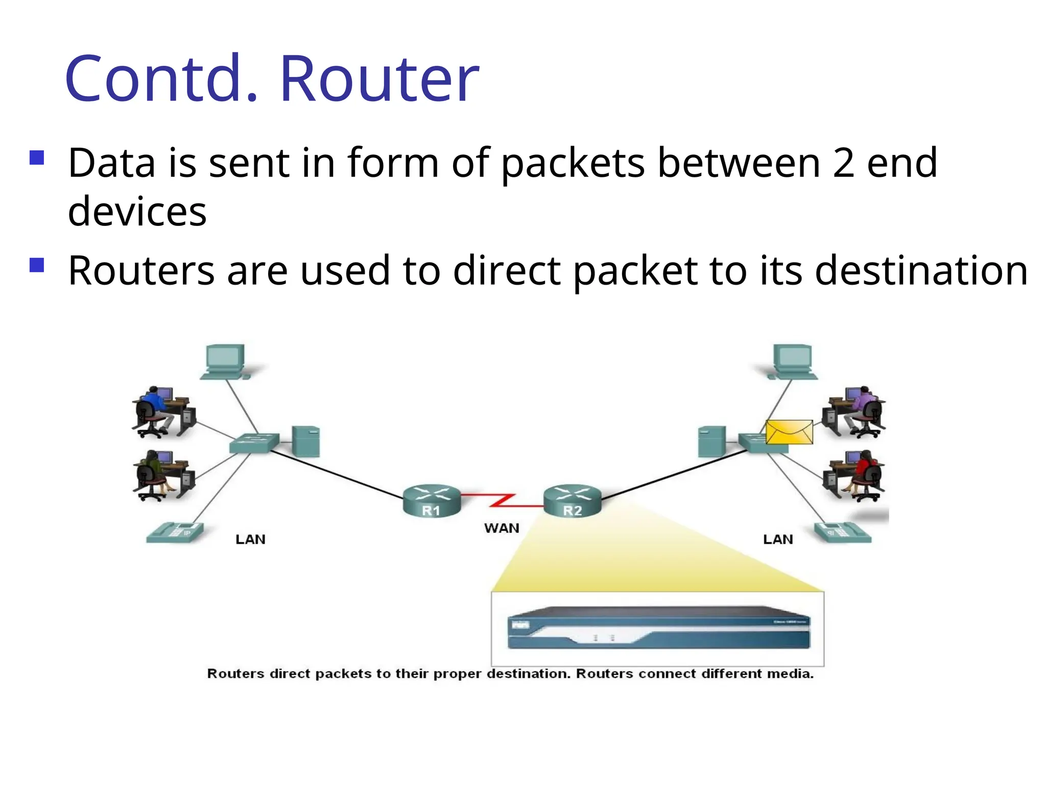
Contd. Router
Datais sent in form of packets between 2 end
devices
Routers are used to direct packet to its destination
36.
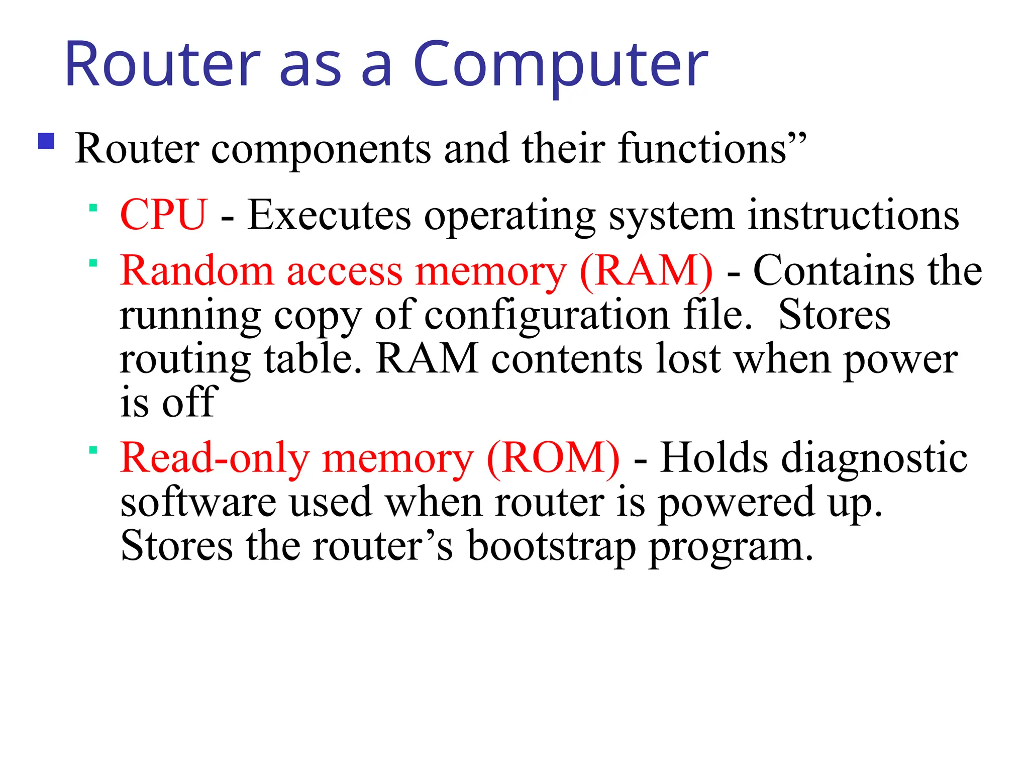
Router as aComputer
Router components and their functions”
CPU - Executes operating system instructions
Random access memory (RAM) - Contains the
running copy of configuration file. Stores
routing table. RAM contents lost when power
is off
Read-only memory (ROM) - Holds diagnostic
software used when router is powered up.
Stores the router’s bootstrap program.
37.
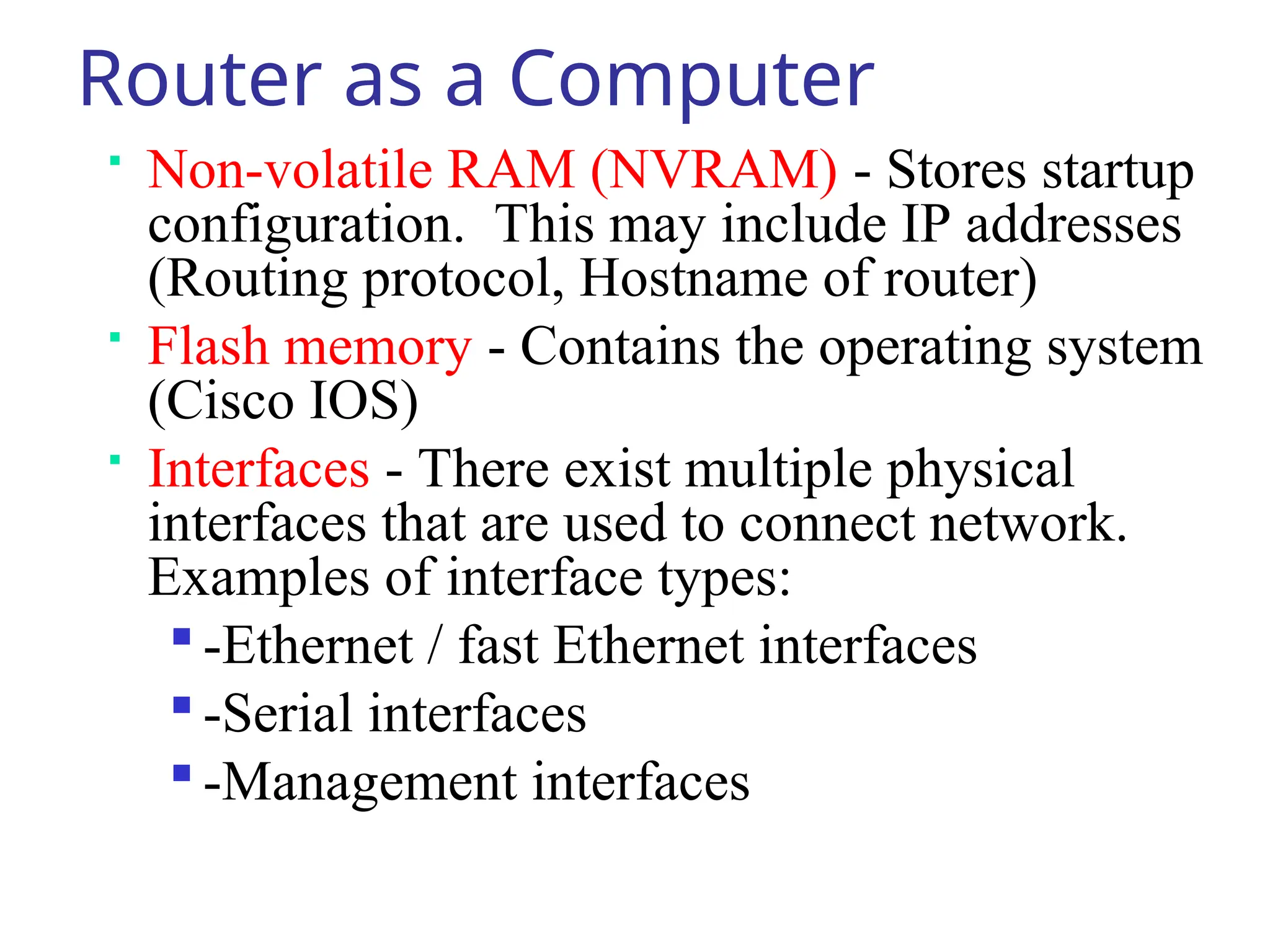
Router as aComputer
Non-volatile RAM (NVRAM) - Stores startup
configuration. This may include IP addresses
(Routing protocol, Hostname of router)
Flash memory - Contains the operating system
(Cisco IOS)
Interfaces - There exist multiple physical
interfaces that are used to connect network.
Examples of interface types:
-Ethernet / fast Ethernet interfaces
-Serial interfaces
-Management interfaces
38.
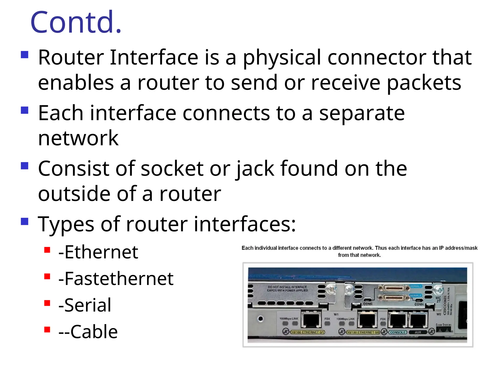
Contd.
Router Interfaceis a physical connector that
enables a router to send or receive packets
Each interface connects to a separate
network
Consist of socket or jack found on the
outside of a router
Types of router interfaces:
-Ethernet
-Fastethernet
-Serial
--Cable
40.
How do routersdiffer from
bridges?
Routers differ from bridges in several respects.
First, bridging occurs at the data link layer or
layer 2,while routing occurs at the network
layer or layer 3 of the OSI model.
Second, bridges use physical or MAC addresses
to make data forwarding decisions. Routers
use a different addressing scheme that occurs
at layer three
41.
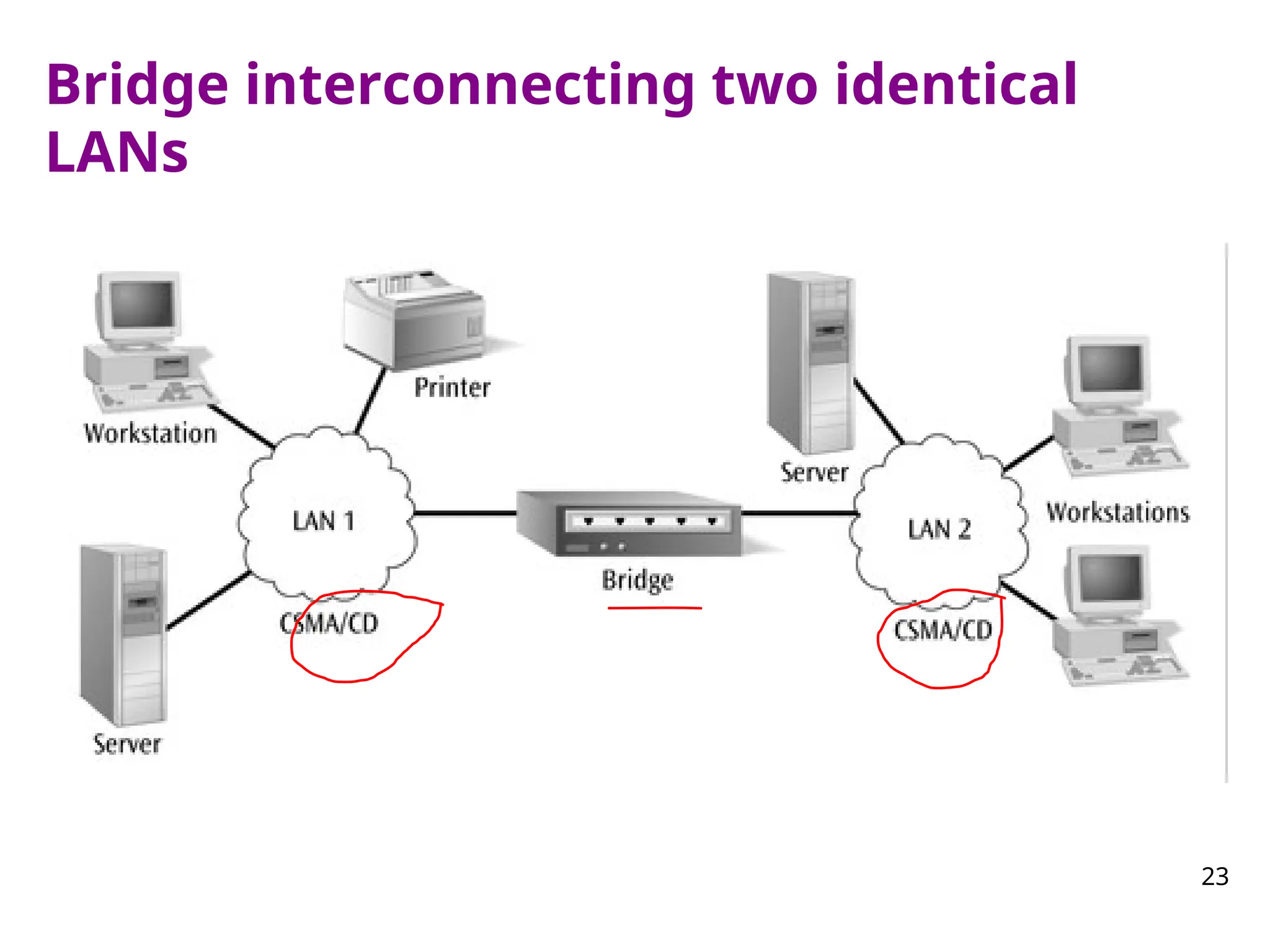
Bridges vs Routers
Bridge:A bridge is a
device that connects
two segments of the
same network. The two
networks being
connected can be alike
or dissimilar.
Bridges are protocol-
independent. They
simply forward packets
without analyzing and
re-routing messages.
Router: A router is a device
that connects two distinct
networks. Routers are
similar to bridges, but
provide additional
functionality, such as the
ability to filter messages
and forward them to
different places based on
various criteria.
The Internet uses routers
extensively to forward
packets from one host to
another.
41
42.
42
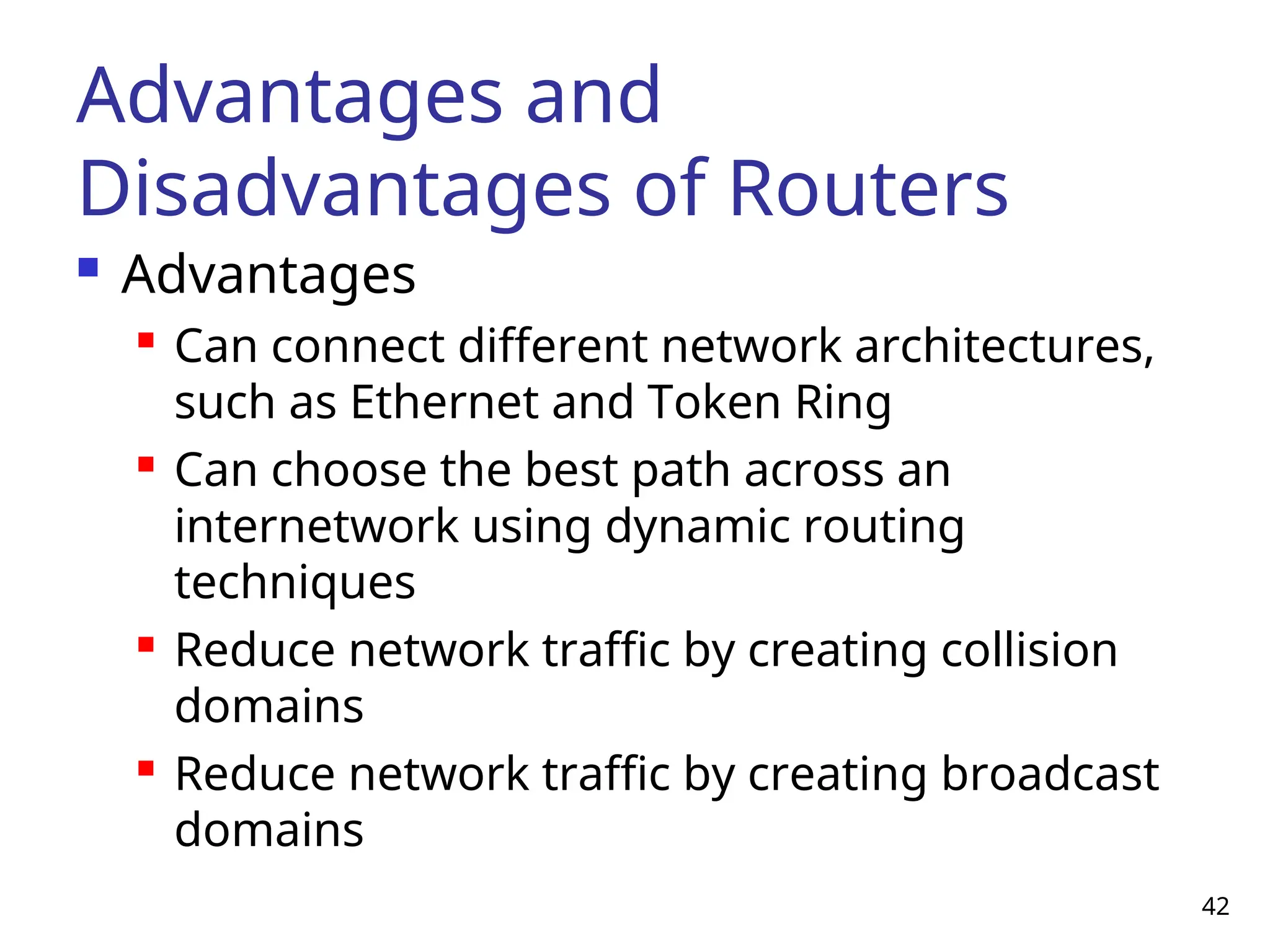
Advantages and
Disadvantages ofRouters
Advantages
Can connect different network architectures,
such as Ethernet and Token Ring
Can choose the best path across an
internetwork using dynamic routing
techniques
Reduce network traffic by creating collision
domains
Reduce network traffic by creating broadcast
domains
43.
43
Advantages and Disadvantagesof
Routers (continued)
Disadvantages
Routers work only with routable network
protocols; most but not all protocols are routable
Routers are more expensive than other devices
Dynamic router communications (inter-router
communication) cause additional network
overhead, which results in less bandwidth for user
data
Routers are slower than other devices because
they must analyze a data transmission from the
Physical through the Network layer
44.
44
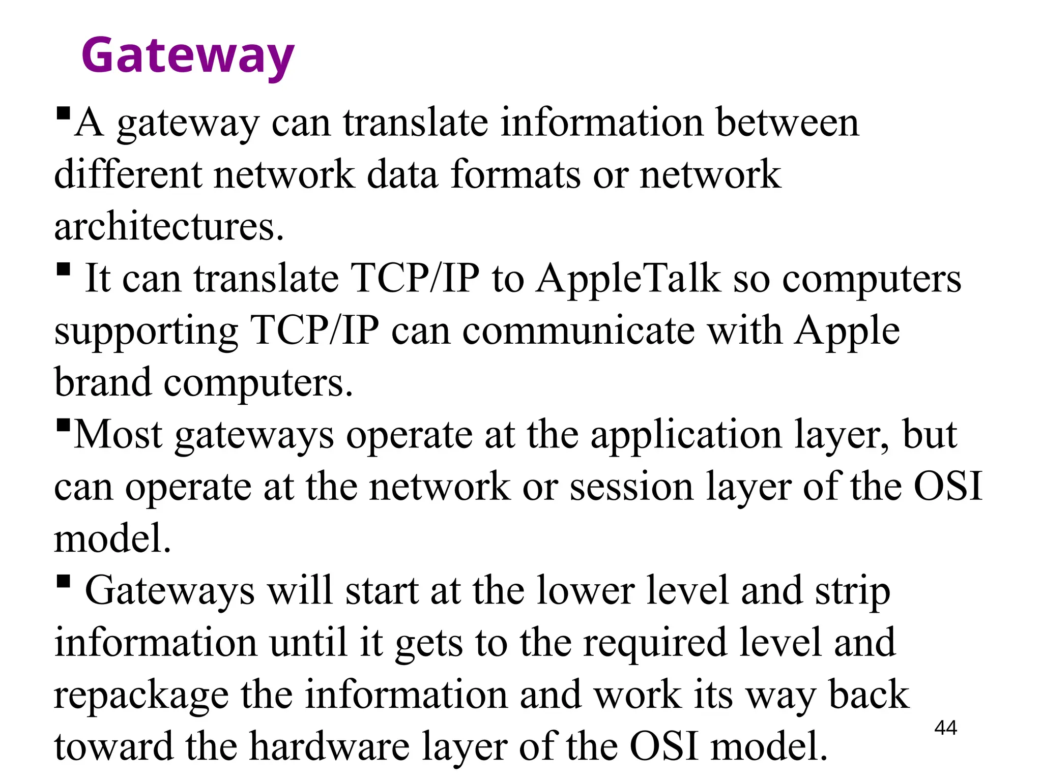
Gateway
A gateway cantranslate information between
different network data formats or network
architectures.
It can translate TCP/IP to AppleTalk so computers
supporting TCP/IP can communicate with Apple
brand computers.
Most gateways operate at the application layer, but
can operate at the network or session layer of the OSI
model.
Gateways will start at the lower level and strip
information until it gets to the required level and
repackage the information and work its way back
toward the hardware layer of the OSI model.
45.
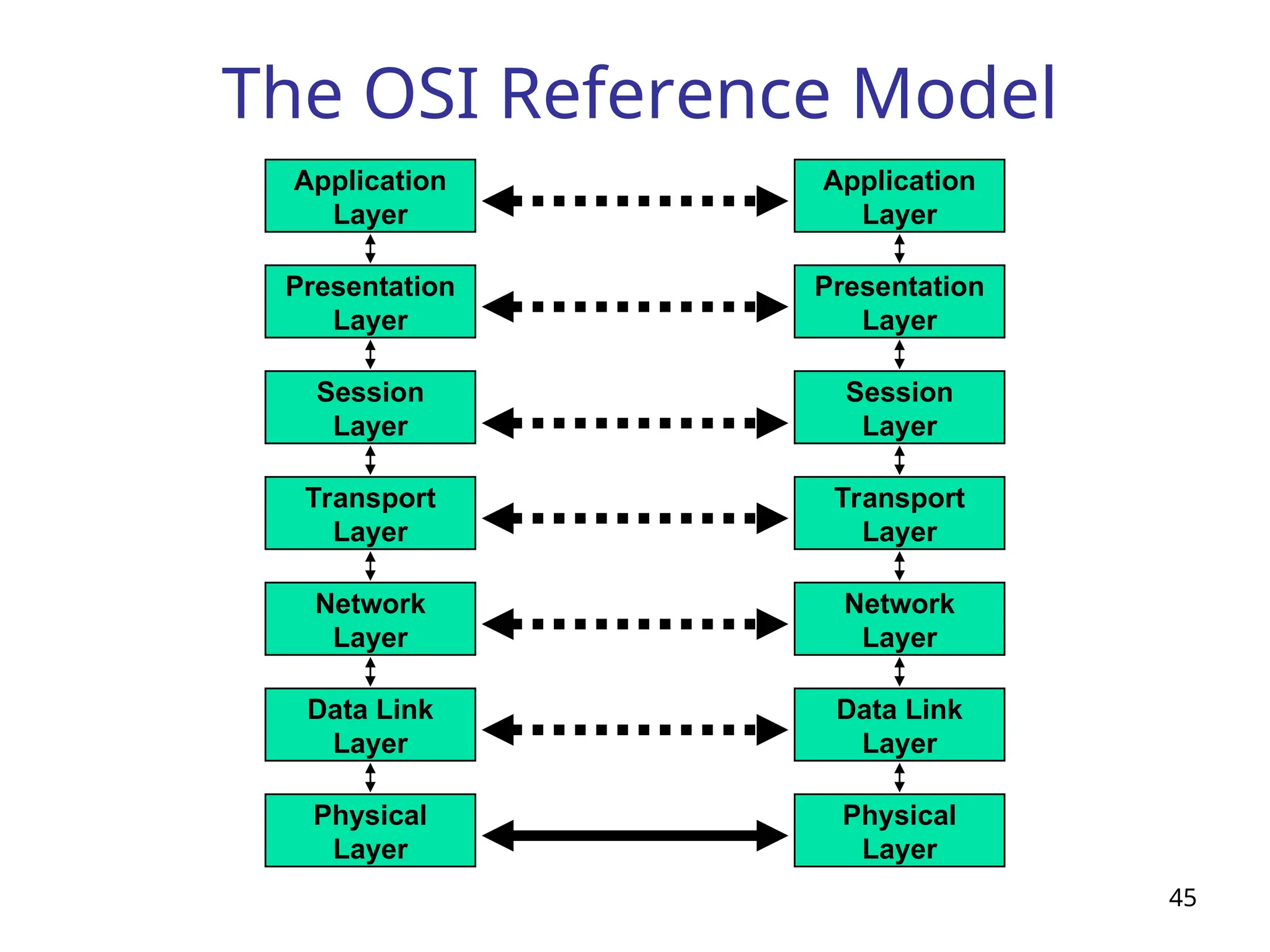
The OSI ReferenceModel
45
Network
Layer
Data Link
Layer
Physical
Layer
Application
Layer
Presentation
Layer
Session
Layer
Transport
Layer
Network
Layer
Data Link
Layer
Physical
Layer
Application
Layer
Presentation
Layer
Session
Layer
Transport
Layer
46.
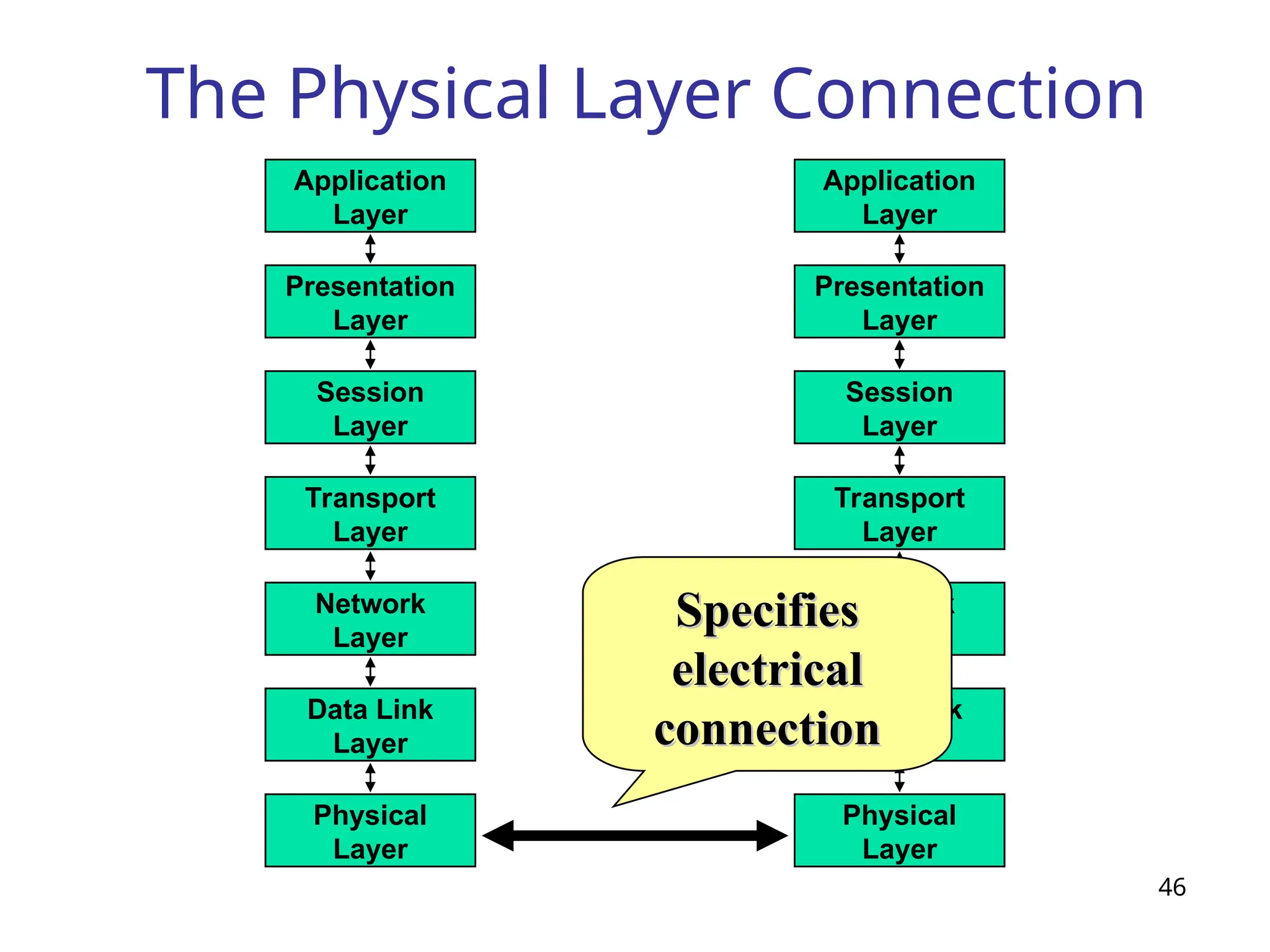
The Physical LayerConnection
46
Network
Layer
Data Link
Layer
Physical
Layer
Application
Layer
Presentation
Layer
Session
Layer
Transport
Layer
Network
Layer
Data Link
Layer
Physical
Layer
Application
Layer
Presentation
Layer
Session
Layer
Transport
Layer
Specifies
Specifies
electrical
electrical
connection
connection
47.
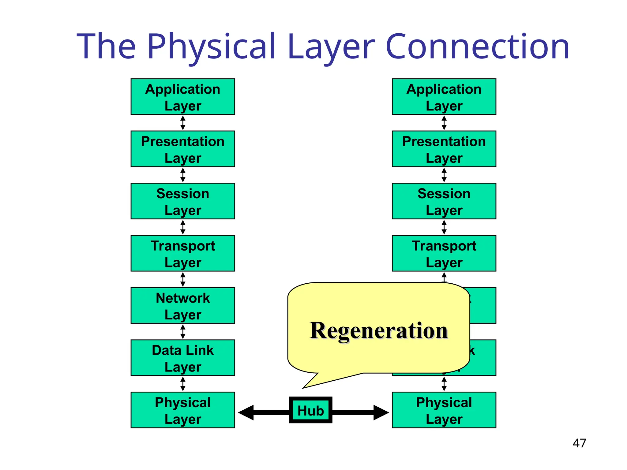
The Physical LayerConnection
47
Network
Layer
Data Link
Layer
Physical
Layer
Application
Layer
Presentation
Layer
Session
Layer
Transport
Layer
Network
Layer
Data Link
Layer
Physical
Layer
Application
Layer
Presentation
Layer
Session
Layer
Transport
Layer
Hub
Amplification
Amplification
Regeneration
Regeneration
48.
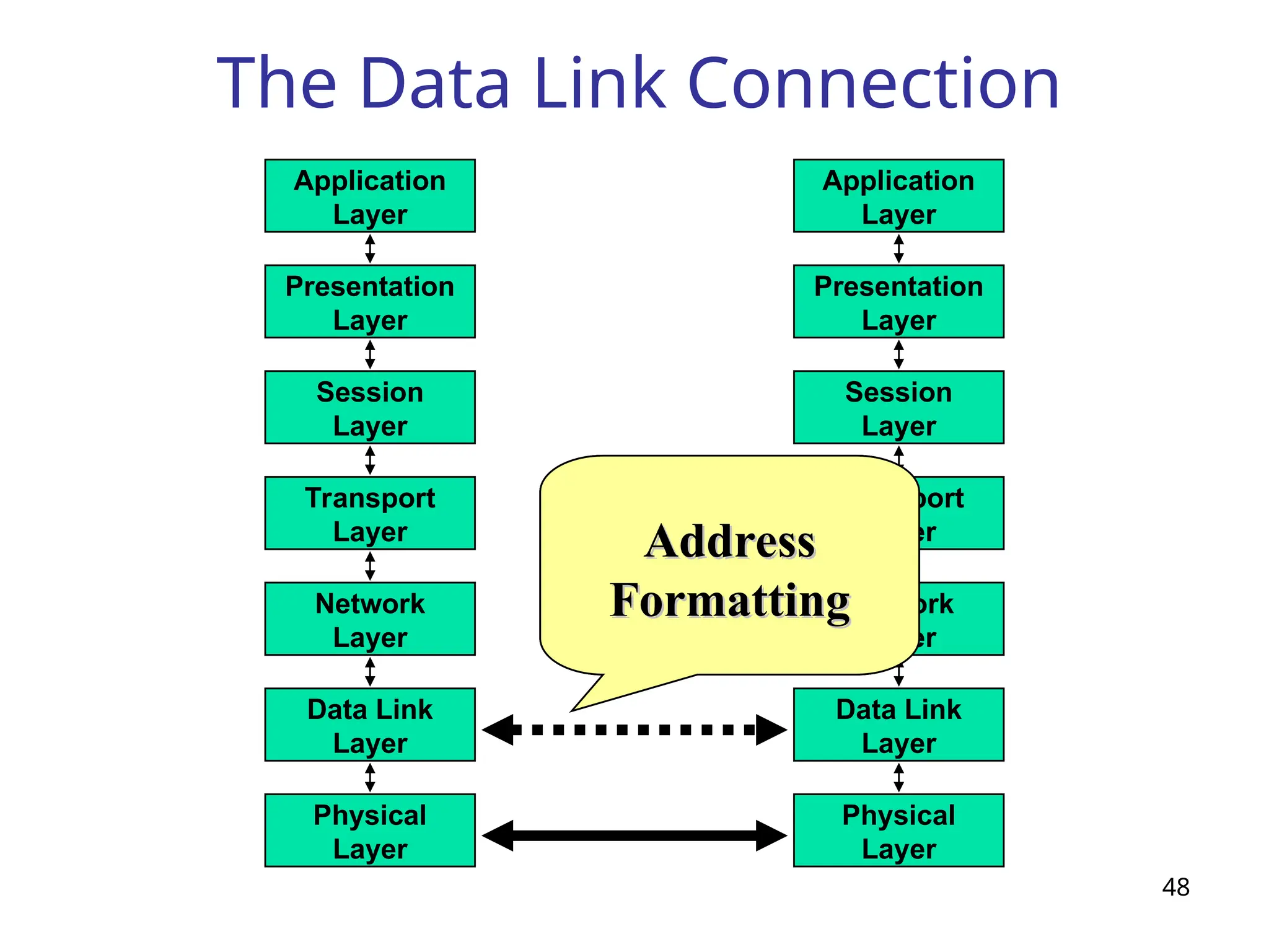
The Data LinkConnection
48
Network
Layer
Data Link
Layer
Physical
Layer
Application
Layer
Presentation
Layer
Session
Layer
Transport
Layer
Network
Layer
Data Link
Layer
Physical
Layer
Application
Layer
Presentation
Layer
Session
Layer
Transport
Layer
Delineation
Delineation
of
of
Data
Data
Error
Error
Detection
Detection
Address
Address
Formatting
Formatting
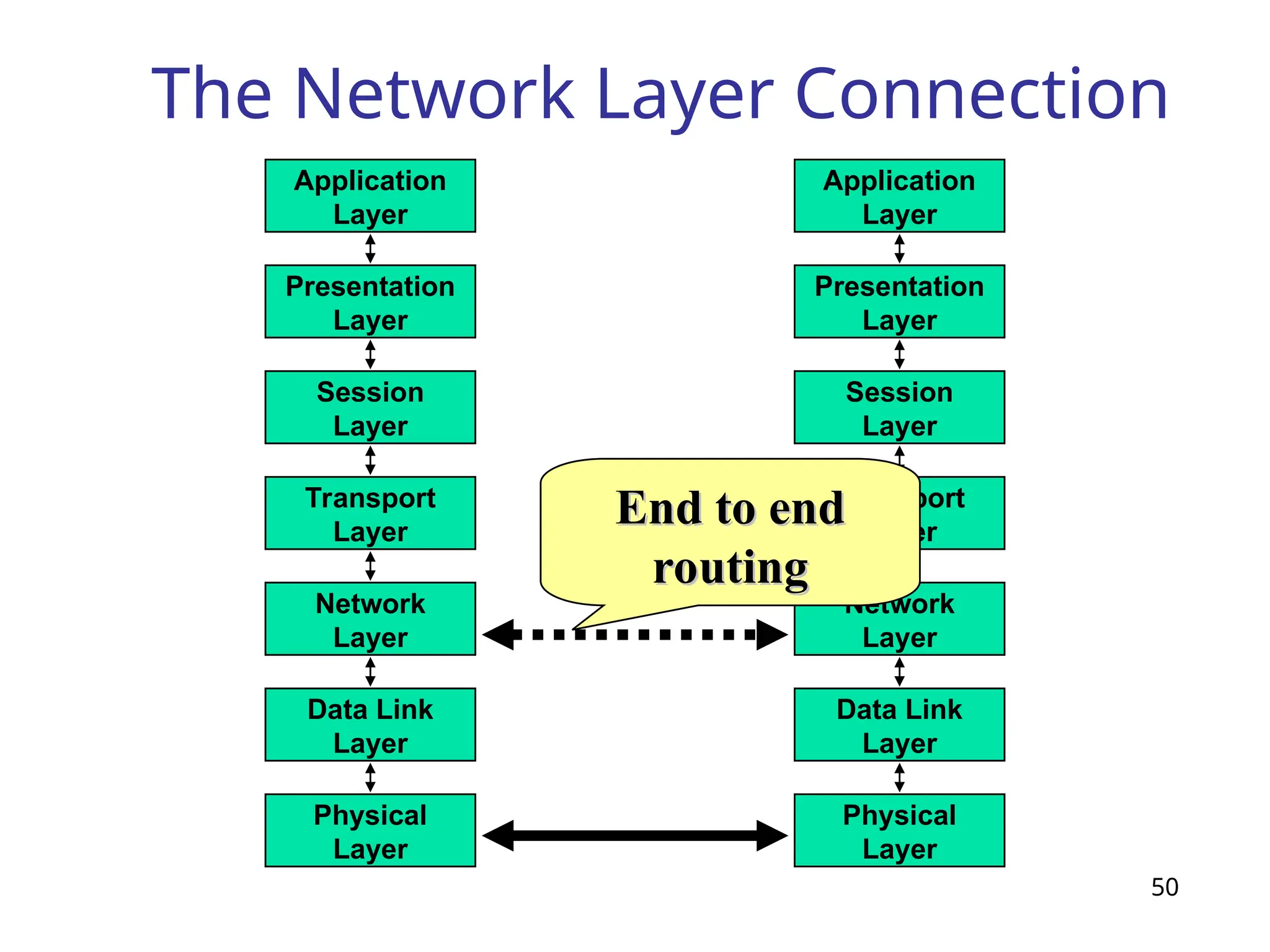
The Network LayerConnection
50
Network
Layer
Data Link
Layer
Physical
Layer
Application
Layer
Presentation
Layer
Session
Layer
Transport
Layer
Network
Layer
Data Link
Layer
Physical
Layer
Application
Layer
Presentation
Layer
Session
Layer
Transport
Layer
End to end
End to end
routing
routing
51.
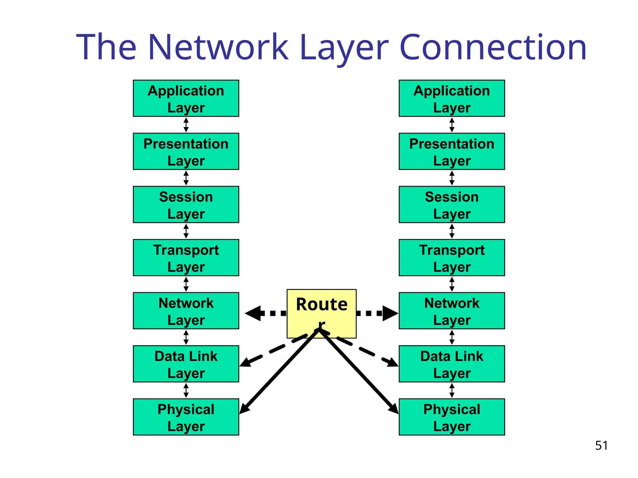
The Network LayerConnection
51
Network
Layer
Data Link
Layer
Physical
Layer
Application
Layer
Presentation
Layer
Session
Layer
Transport
Layer
Network
Layer
Data Link
Layer
Physical
Layer
Application
Layer
Presentation
Layer
Session
Layer
Transport
Layer
Route
r
52.
52
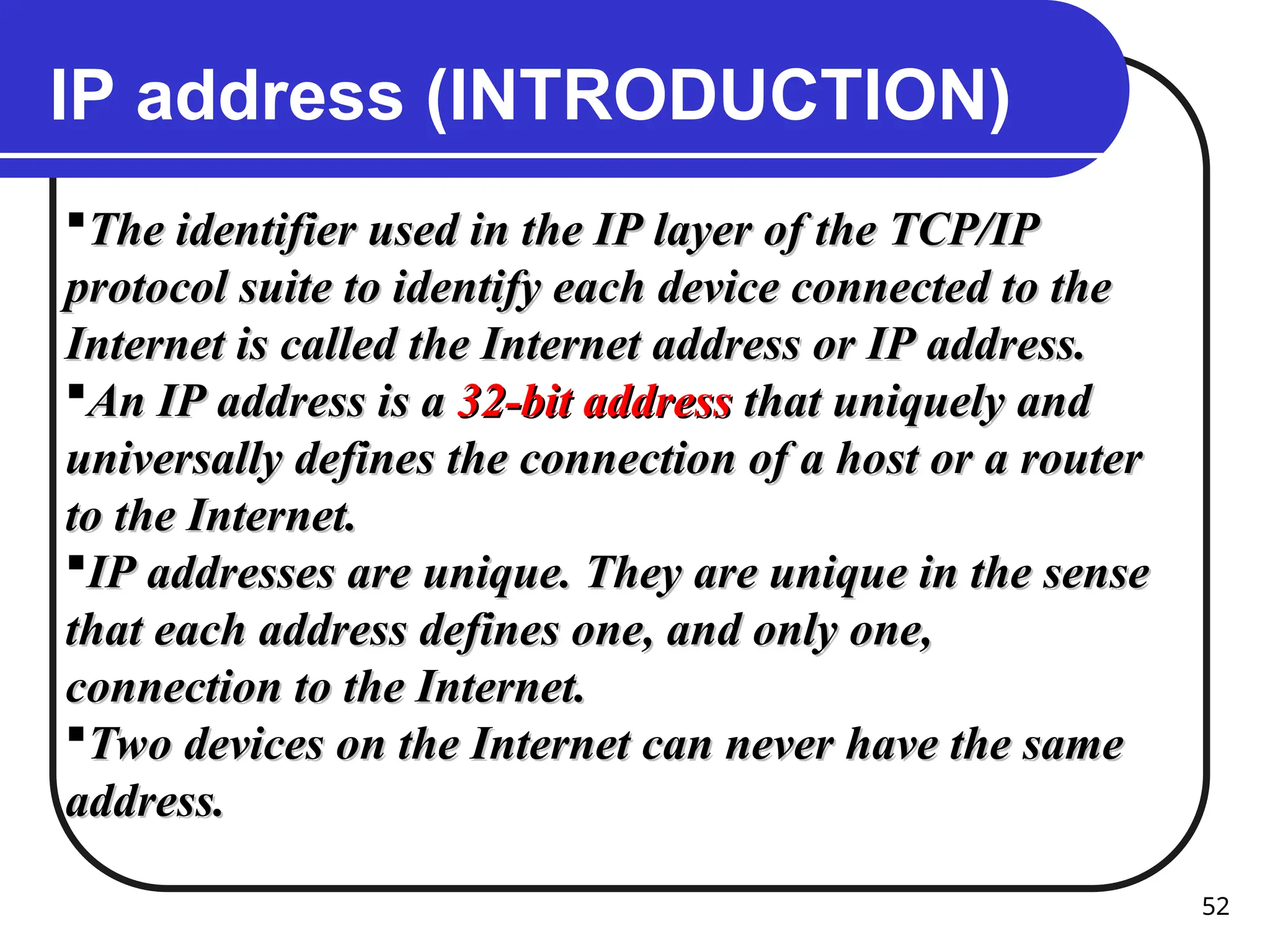
IP address (INTRODUCTION)
Theidentifier used in the IP layer of the TCP/IP
The identifier used in the IP layer of the TCP/IP
protocol suite to identify each device connected to the
protocol suite to identify each device connected to the
Internet is called the Internet address or IP address.
Internet is called the Internet address or IP address.
An IP address is a
An IP address is a 32-bit address
32-bit address that uniquely and
that uniquely and
universally defines the connection of a host or a router
universally defines the connection of a host or a router
to the Internet.
to the Internet.
IP addresses are unique. They are unique in the sense
IP addresses are unique. They are unique in the sense
that each address defines one, and only one,
that each address defines one, and only one,
connection to the Internet.
connection to the Internet.
Two devices on the Internet can never have the same
Two devices on the Internet can never have the same
address.
address.
53.
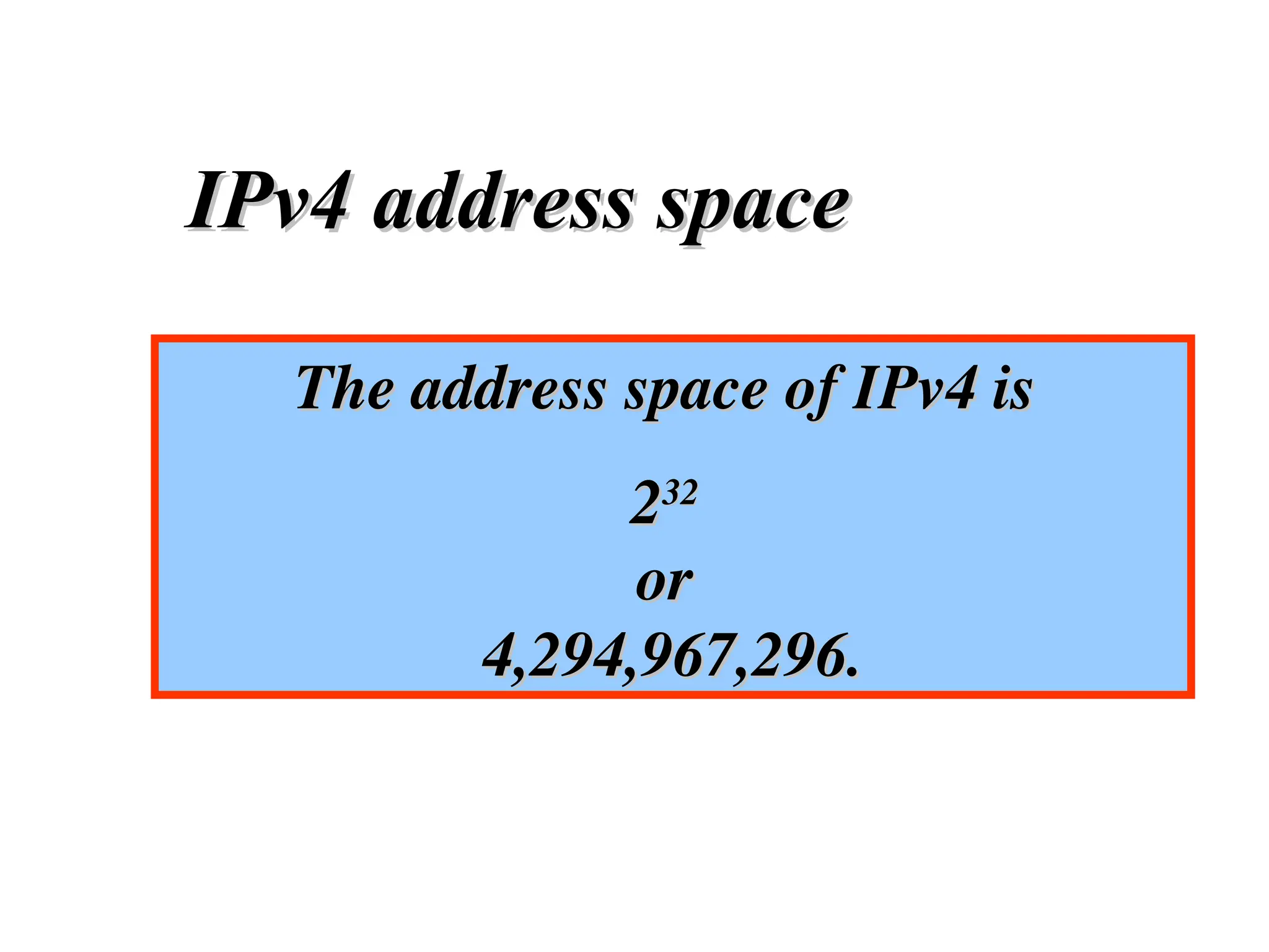
The address spaceof IPv4 is
The address space of IPv4 is
2
232
32
or
or
4,294,967,296.
4,294,967,296.
IPv4 address space
IPv4 address space
55
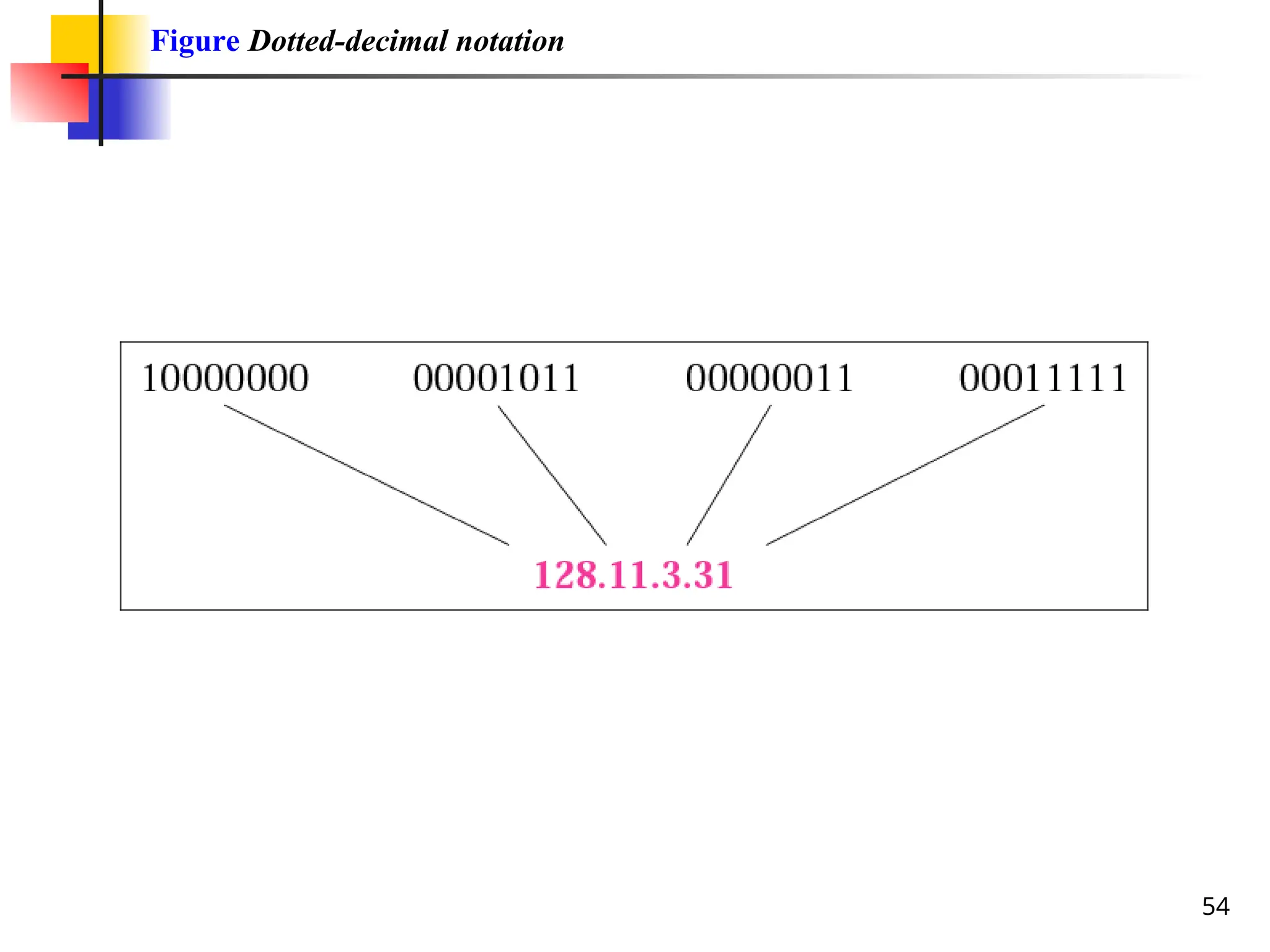
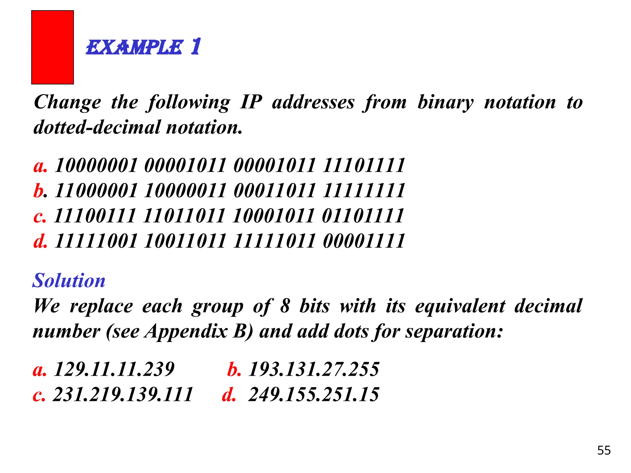
Change the followingIP addresses from binary notation to
dotted-decimal notation.
a. 10000001 00001011 00001011 11101111
b. 11000001 10000011 00011011 11111111
c. 11100111 11011011 10001011 01101111
d. 11111001 10011011 11111011 00001111
Example 1
Solution
We replace each group of 8 bits with its equivalent decimal
number (see Appendix B) and add dots for separation:
a. 129.11.11.239 b. 193.131.27.255
c. 231.219.139.111 d. 249.155.251.15
56.
56
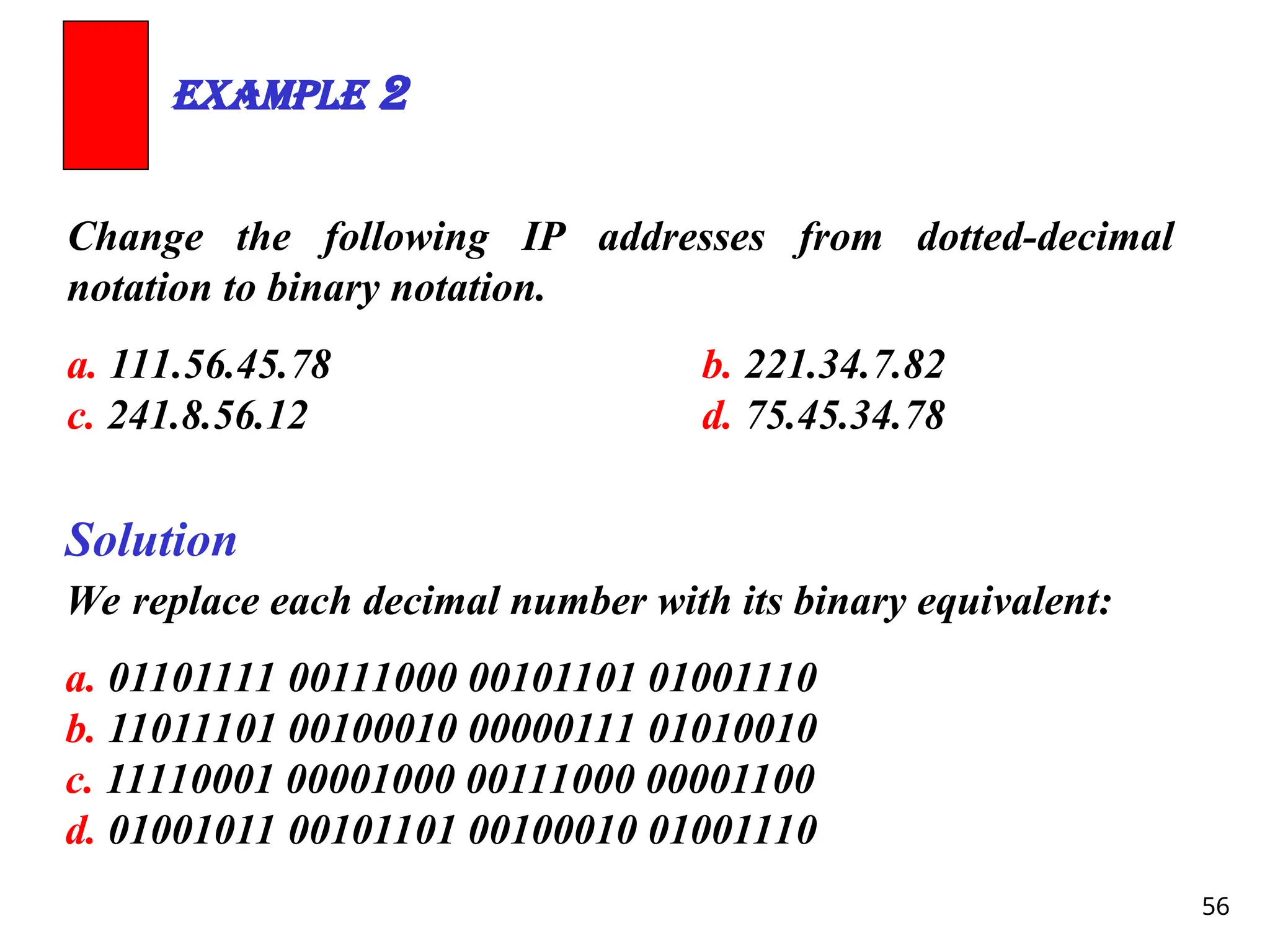
Change the followingIP addresses from dotted-decimal
notation to binary notation.
a. 111.56.45.78 b. 221.34.7.82
c. 241.8.56.12 d. 75.45.34.78
Example 2
Solution
We replace each decimal number with its binary equivalent:
a. 01101111 00111000 00101101 01001110
b. 11011101 00100010 00000111 01010010
c. 11110001 00001000 00111000 00001100
d. 01001011 00101101 00100010 01001110
57.
57
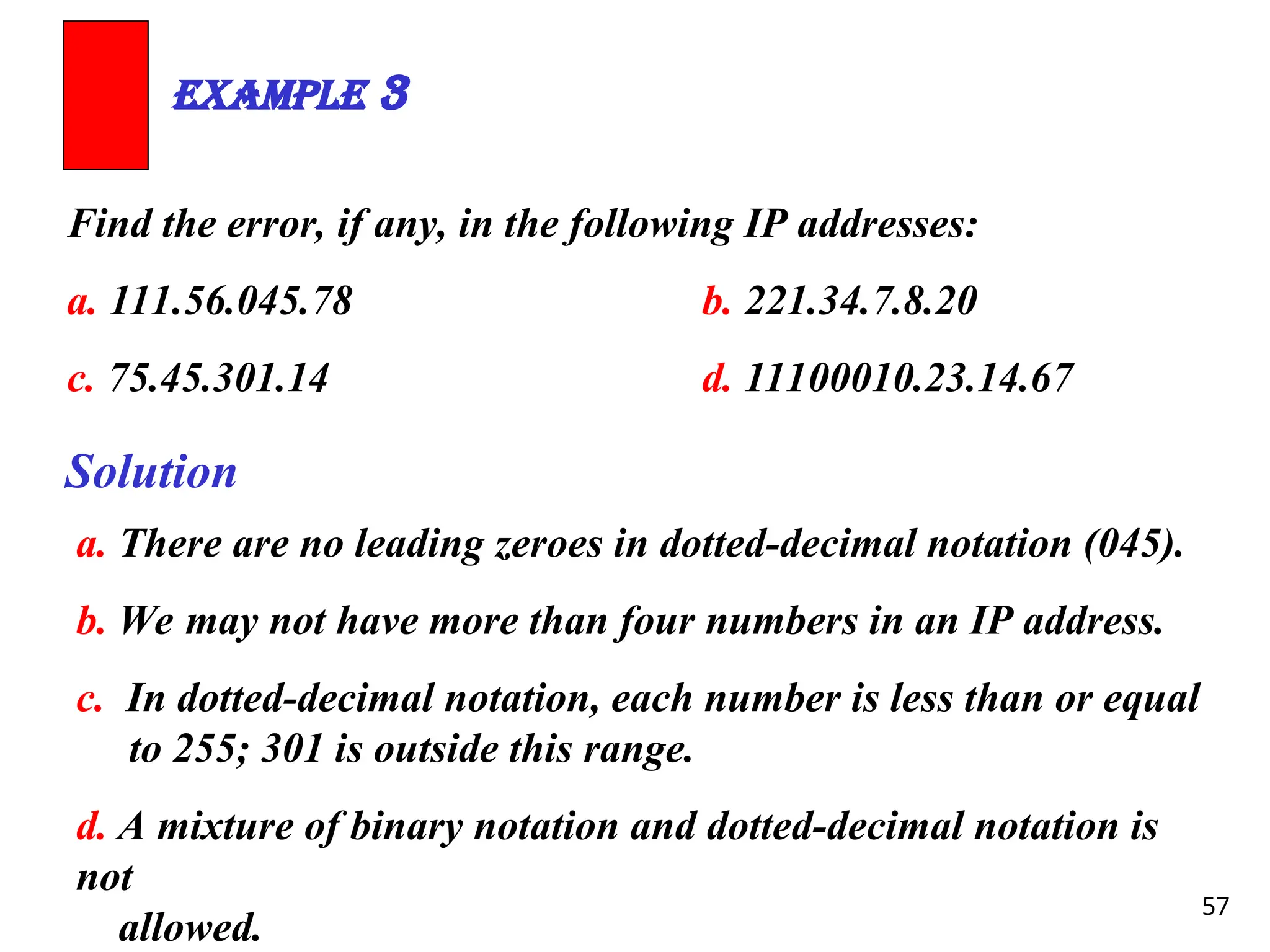
Find the error,if any, in the following IP addresses:
a. 111.56.045.78 b. 221.34.7.8.20
c. 75.45.301.14 d. 11100010.23.14.67
Example 3
Solution
a. There are no leading zeroes in dotted-decimal notation (045).
b. We may not have more than four numbers in an IP address.
c. In dotted-decimal notation, each number is less than or equal
to 255; 301 is outside this range.
d. A mixture of binary notation and dotted-decimal notation is
not
allowed.
58.
58
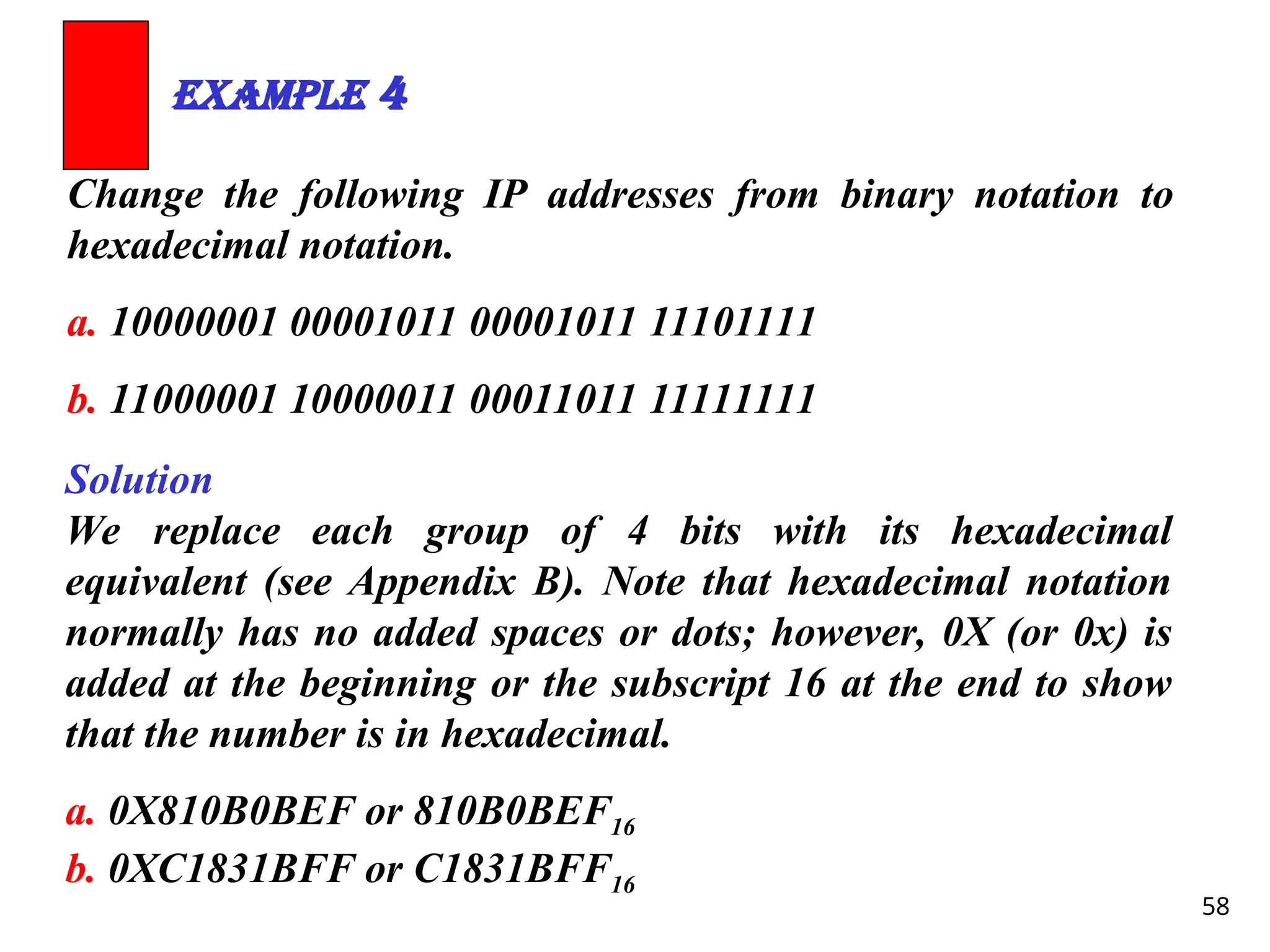
Change the followingIP addresses from binary notation to
hexadecimal notation.
a. 10000001 00001011 00001011 11101111
b. 11000001 10000011 00011011 11111111
Example 4
Solution
We replace each group of 4 bits with its hexadecimal
equivalent (see Appendix B). Note that hexadecimal notation
normally has no added spaces or dots; however, 0X (or 0x) is
added at the beginning or the subscript 16 at the end to show
that the number is in hexadecimal.
a. 0X810B0BEF or 810B0BEF16
b. 0XC1831BFF or C1831BFF16
59.
59
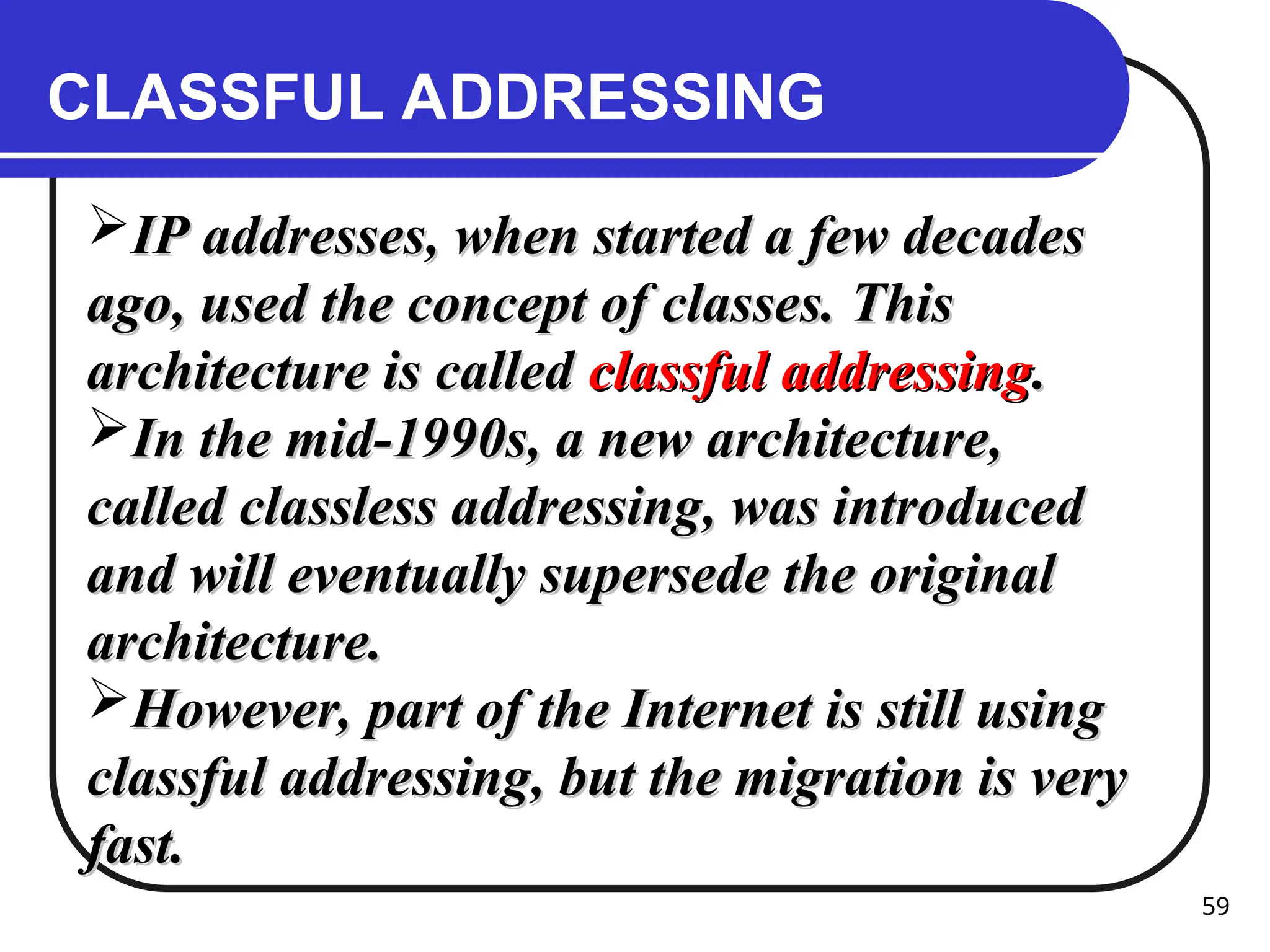
CLASSFUL ADDRESSING
IP addresses,when started a few decades
IP addresses, when started a few decades
ago, used the concept of classes. This
ago, used the concept of classes. This
architecture is called
architecture is called classful addressing
classful addressing.
.
In the mid-1990s, a new architecture,
In the mid-1990s, a new architecture,
called classless addressing, was introduced
called classless addressing, was introduced
and will eventually supersede the original
and will eventually supersede the original
architecture.
architecture.
However, part of the Internet is still using
However, part of the Internet is still using
classful addressing, but the migration is very
classful addressing, but the migration is very
fast.
fast.
60.
60
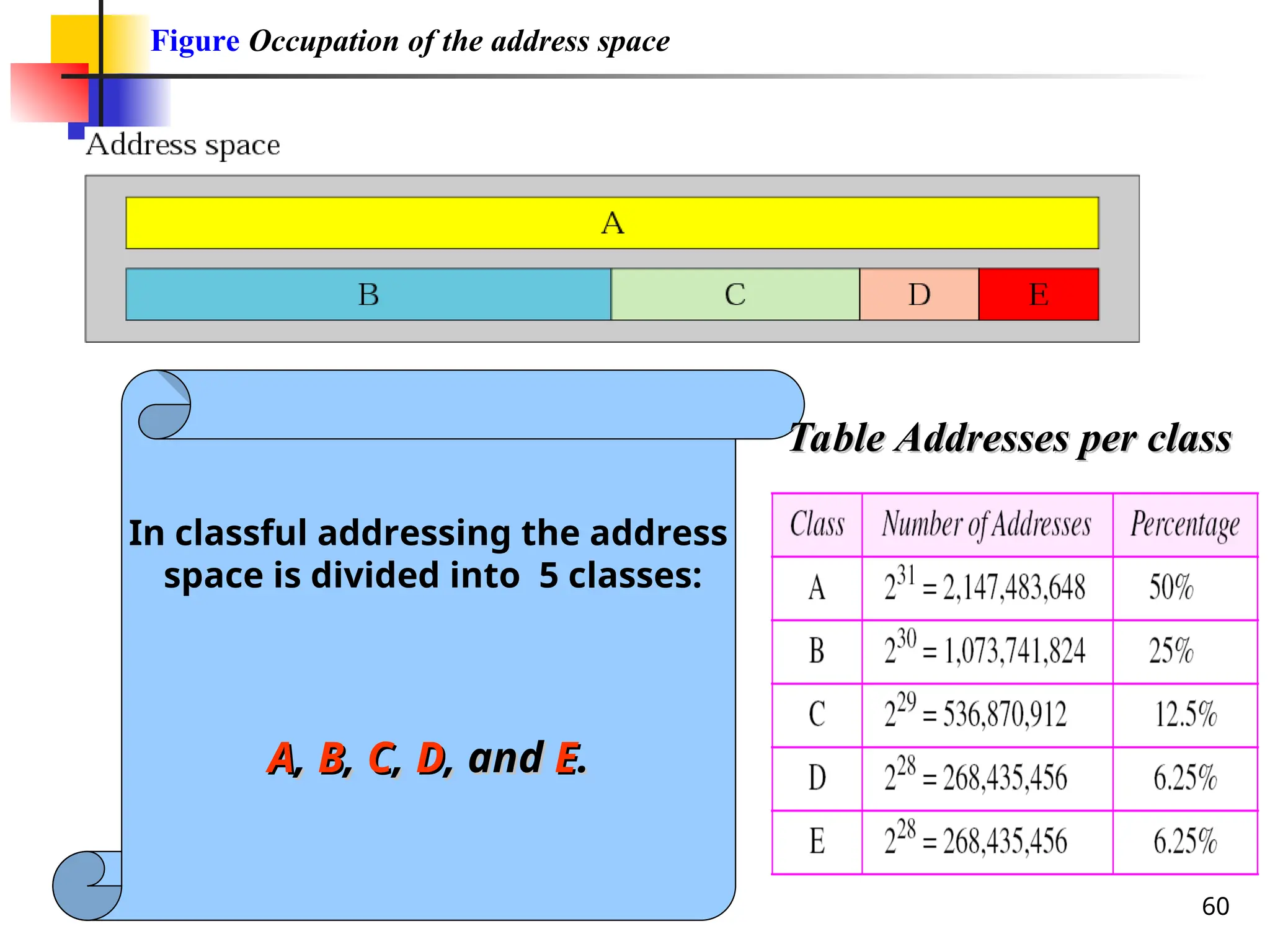
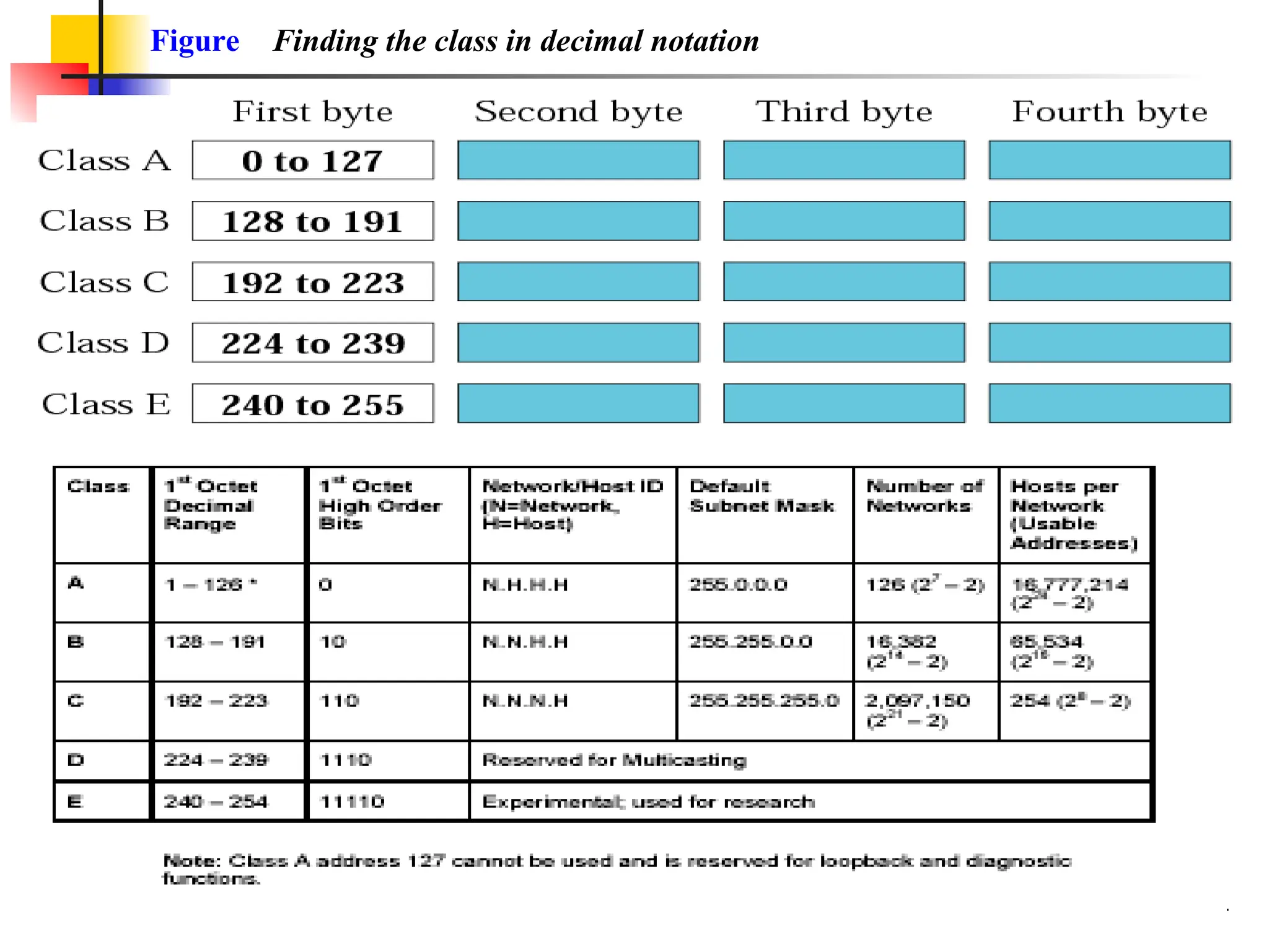
Figure Occupation ofthe address space
In classful addressing the address
space is divided into 5 classes:
A
A,
, B
B,
, C
C,
, D
D, and
, and E
E.
.
Table Addresses per class
Table Addresses per class
63
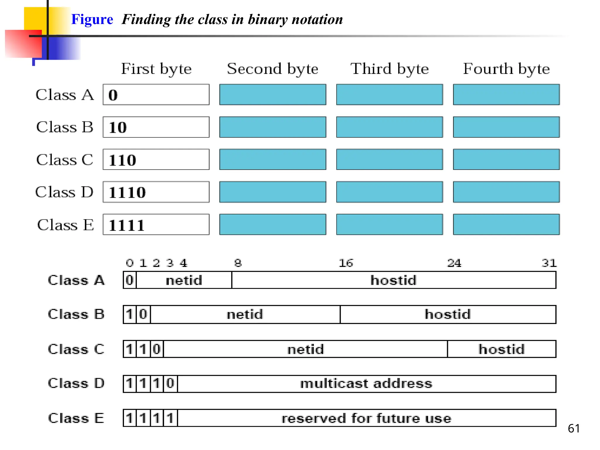
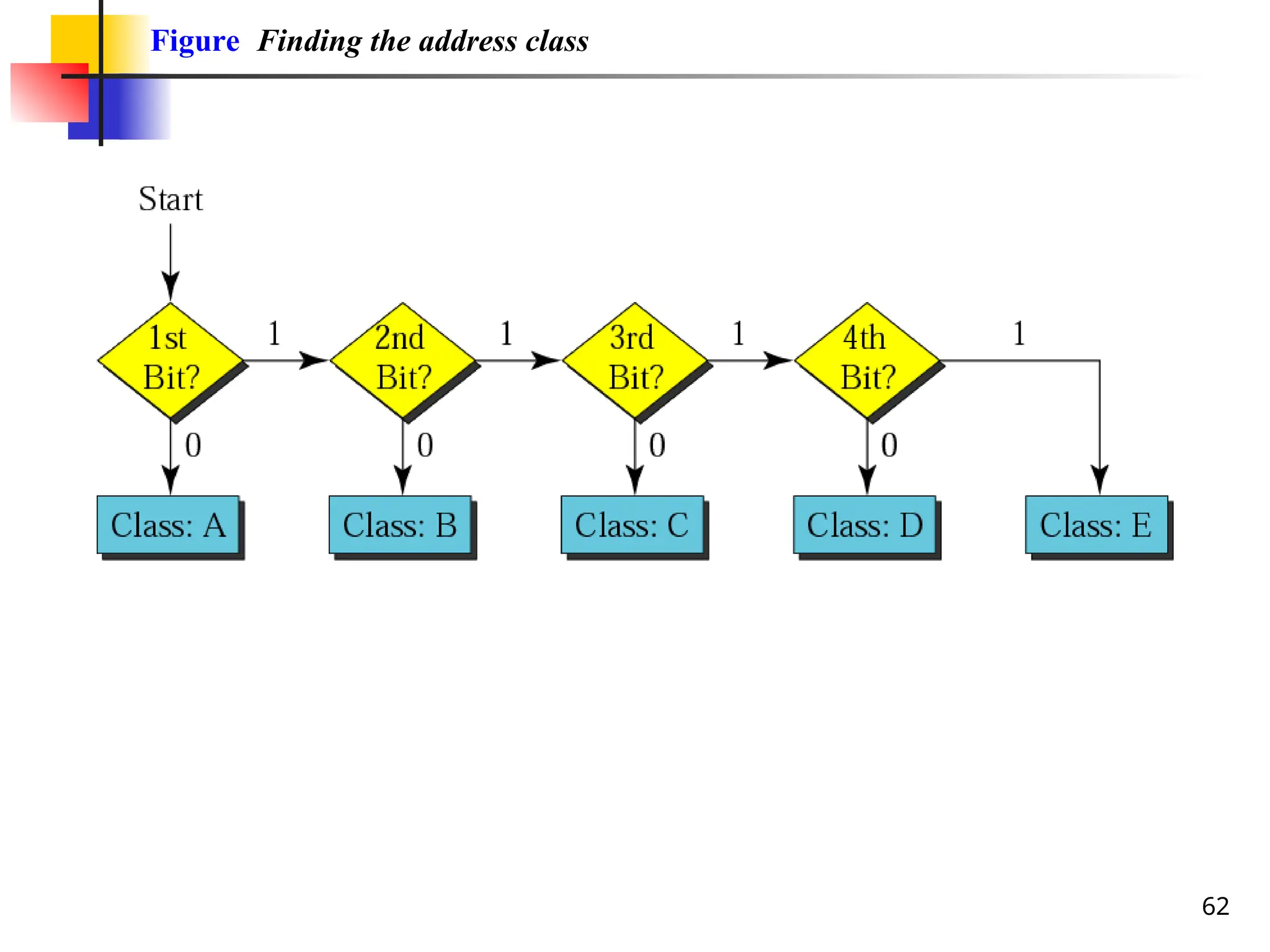
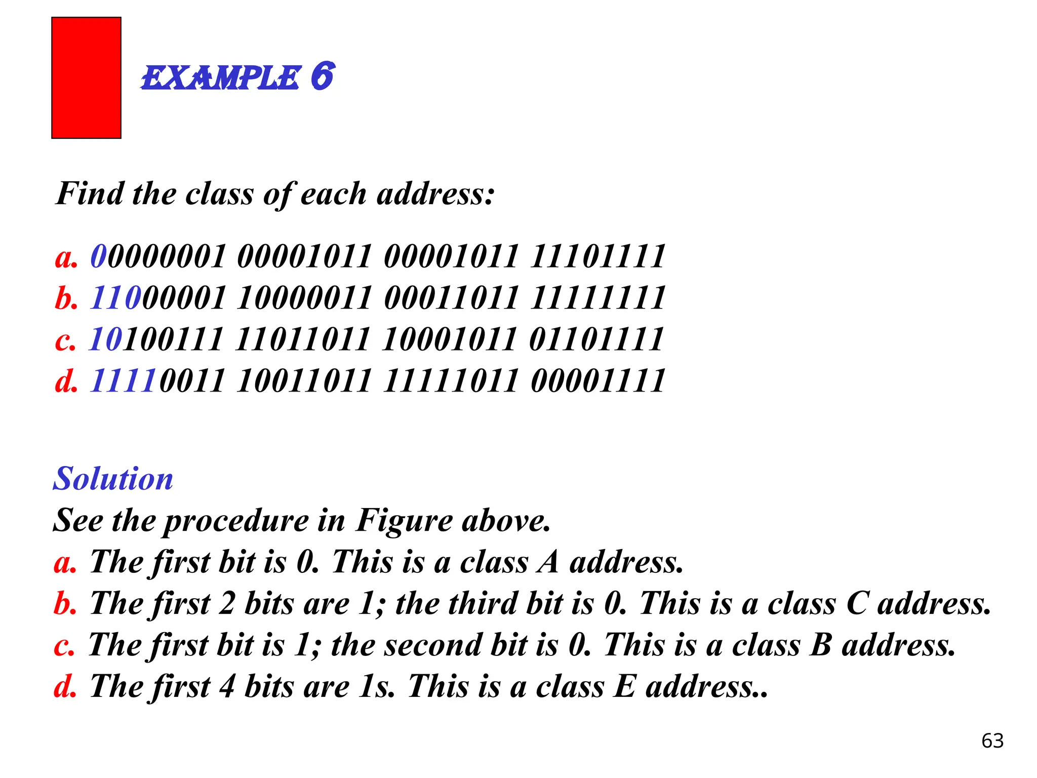
Find the classof each address:
a. 00000001 00001011 00001011 11101111
b. 11000001 10000011 00011011 11111111
c. 10100111 11011011 10001011 01101111
d. 11110011 10011011 11111011 00001111
Example 6
Solution
See the procedure in Figure above.
a. The first bit is 0. This is a class A address.
b. The first 2 bits are 1; the third bit is 0. This is a class C address.
c. The first bit is 1; the second bit is 0. This is a class B address.
d. The first 4 bits are 1s. This is a class E address..
65
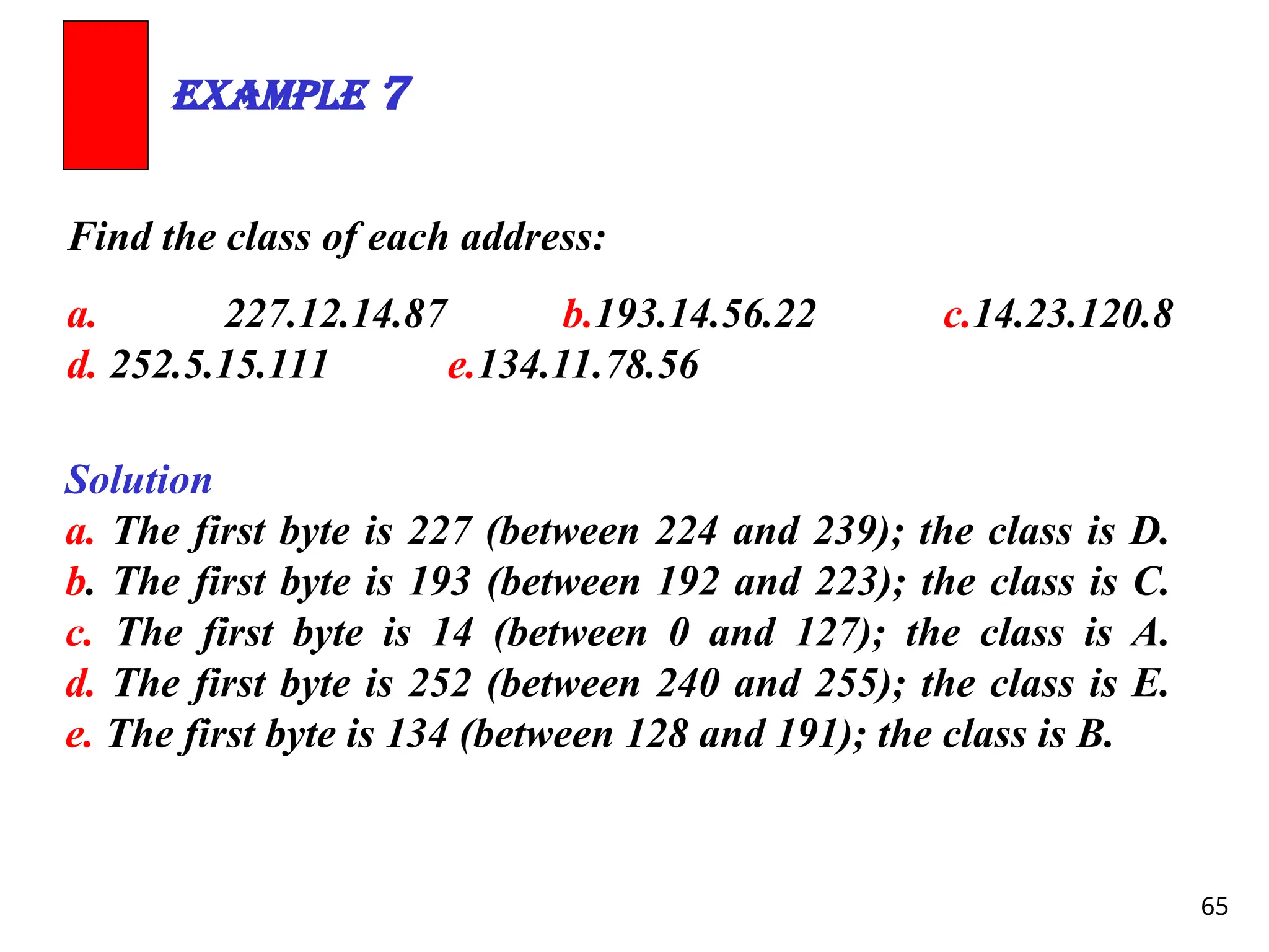
Find the classof each address:
a. 227.12.14.87 b.193.14.56.22 c.14.23.120.8
d. 252.5.15.111 e.134.11.78.56
Example 7
Solution
a. The first byte is 227 (between 224 and 239); the class is D.
b. The first byte is 193 (between 192 and 223); the class is C.
c. The first byte is 14 (between 0 and 127); the class is A.
d. The first byte is 252 (between 240 and 255); the class is E.
e. The first byte is 134 (between 128 and 191); the class is B.
66.
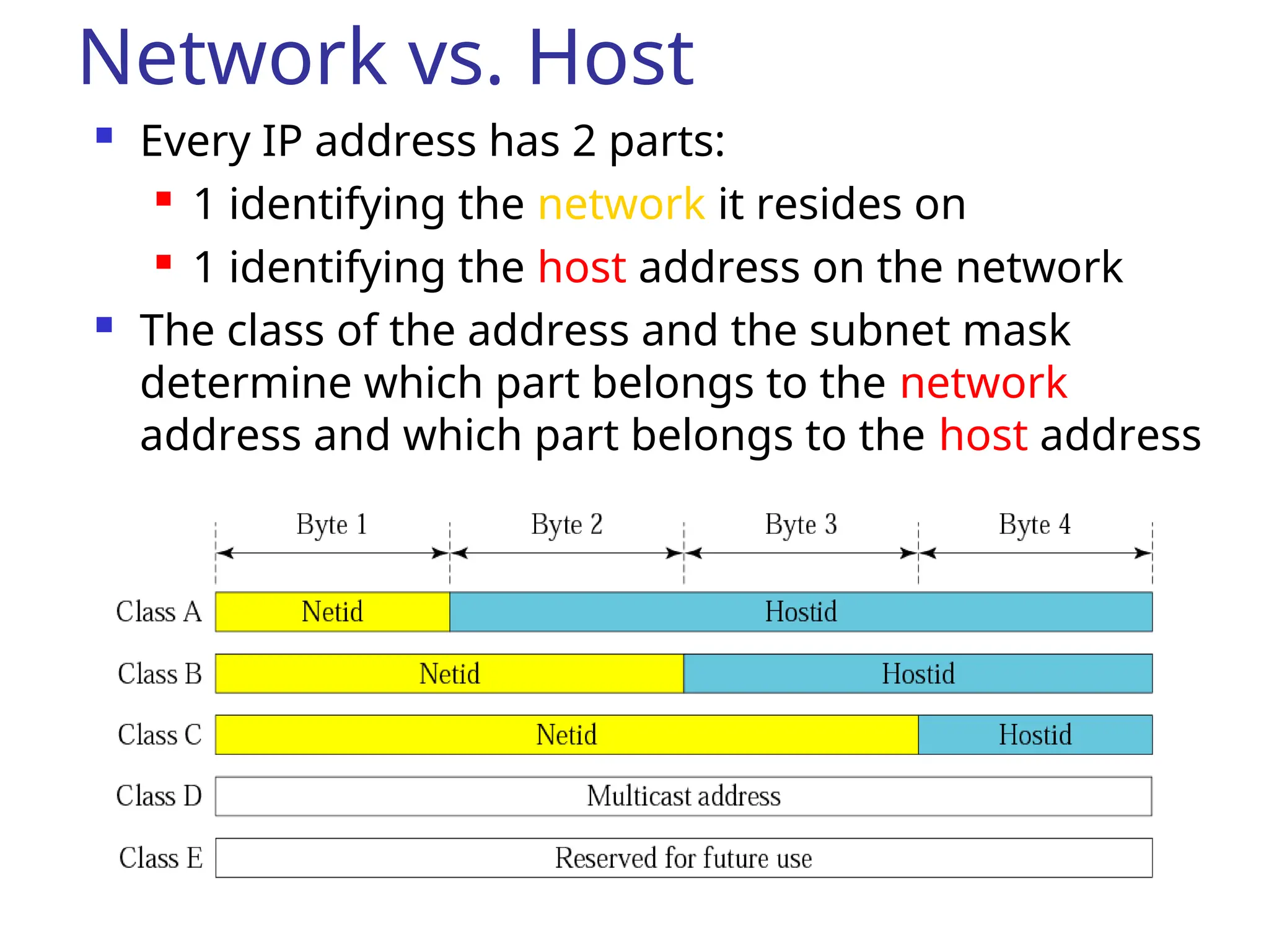
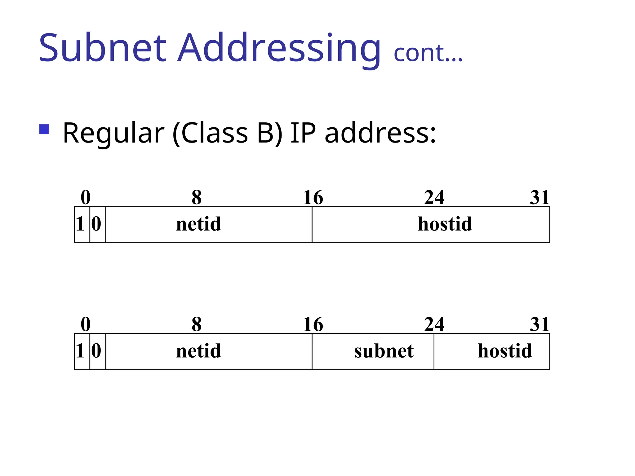
Network vs. Host
Every IP address has 2 parts:
1 identifying the network it resides on
1 identifying the host address on the network
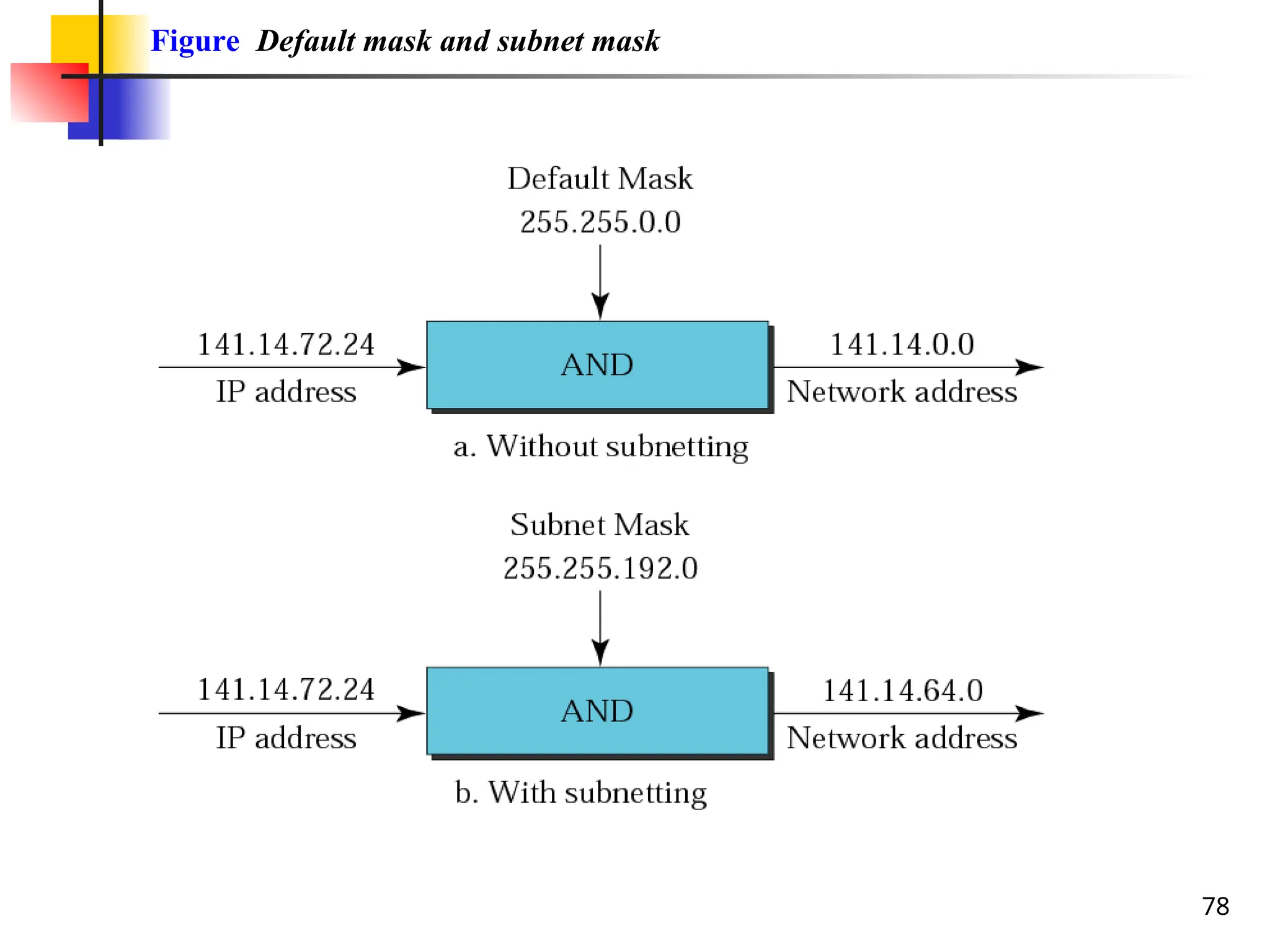
The class of the address and the subnet mask
determine which part belongs to the network
address and which part belongs to the host address
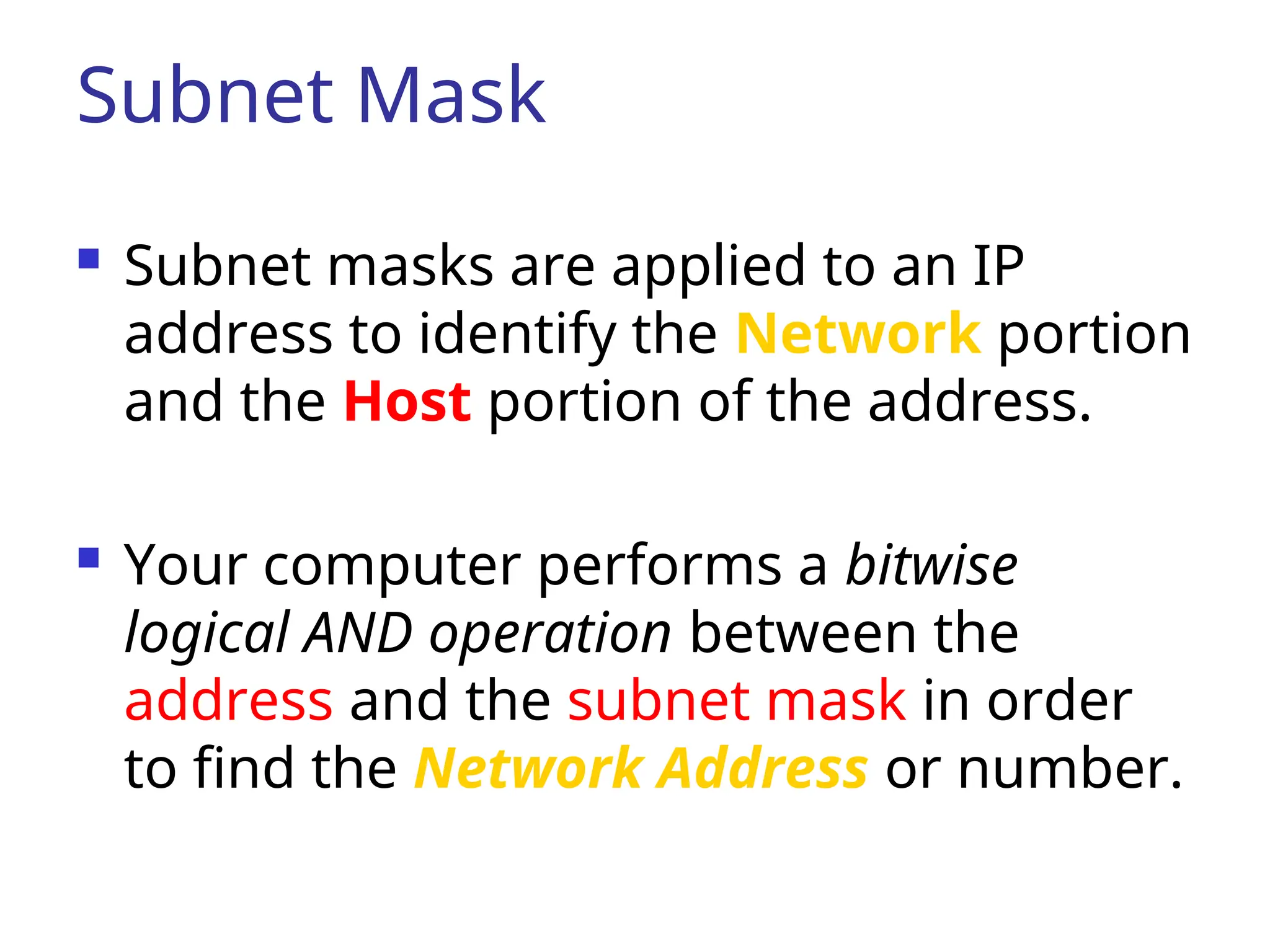
Subnet Mask
Subnetmasks are applied to an IP
address to identify the Network portion
and the Host portion of the address.
Your computer performs a bitwise
logical AND operation between the
address and the subnet mask in order
to find the Network Address or number.
69.
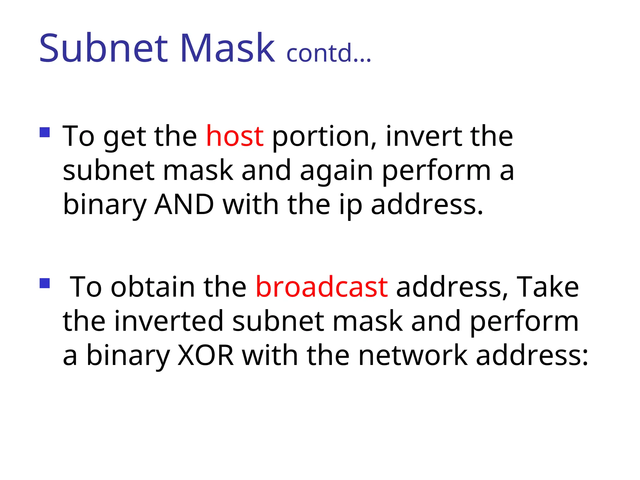
Subnet Mask contd…
To get the host portion, invert the
subnet mask and again perform a
binary AND with the ip address.
To obtain the broadcast address, Take
the inverted subnet mask and perform
a binary XOR with the network address:
70.
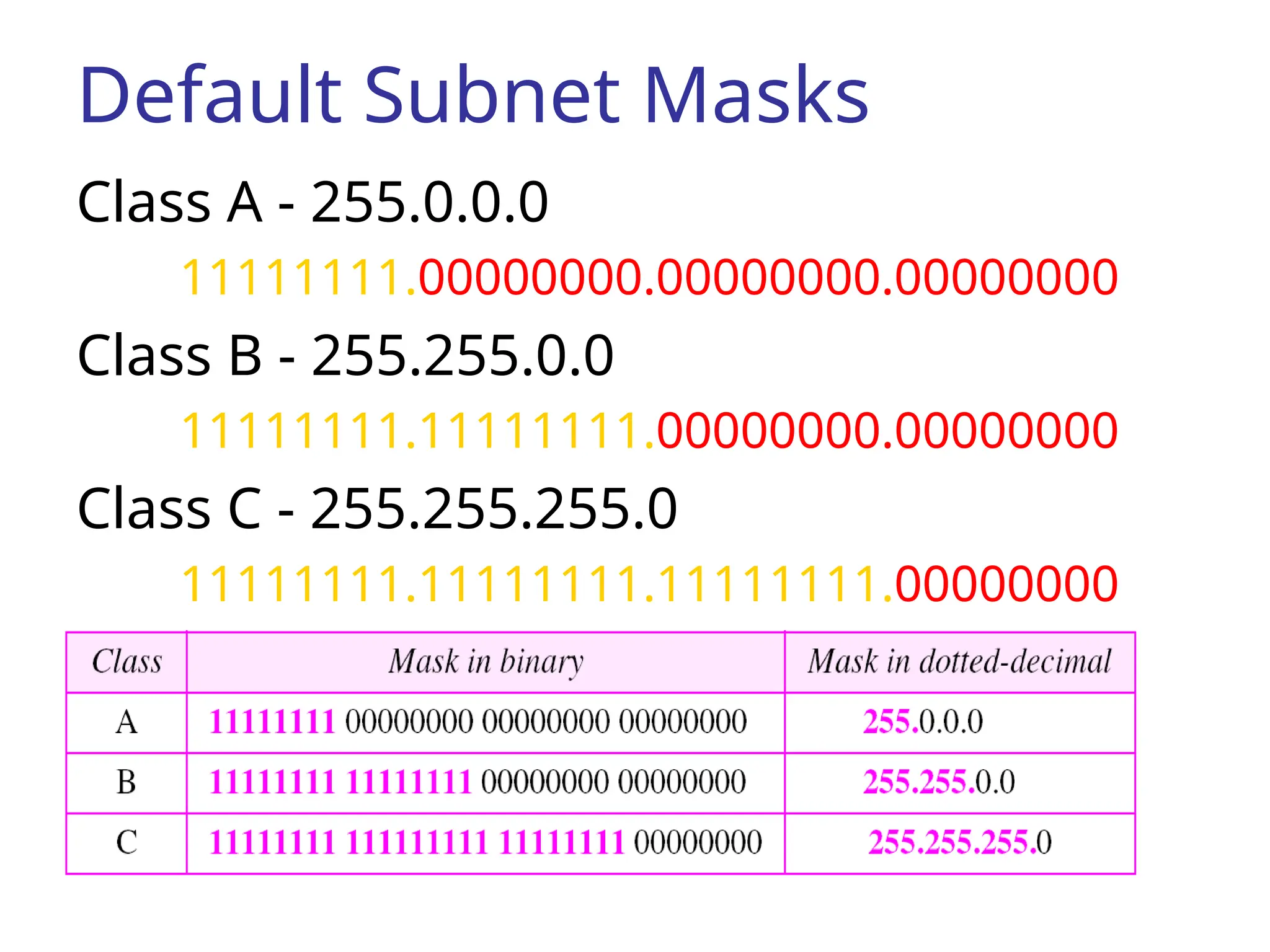
Default Subnet Masks
ClassA - 255.0.0.0
11111111.00000000.00000000.00000000
Class B - 255.255.0.0
11111111.11111111.00000000.00000000
Class C - 255.255.255.0
11111111.11111111.11111111.00000000
71.
Example
IP Address140.179.240.200
It’s a Class B, so the subnet mask is:
255.255.0.0
ip address : 10001100.10110011.11110000.11001000
subnet mask : 11111111.11111111.00000000.00000000
-----------------------------------------------------------AND
Network address :10001100.10110011.00000000.00000000
which translated back to dotted decimal notation is 140.179.0.0
72.
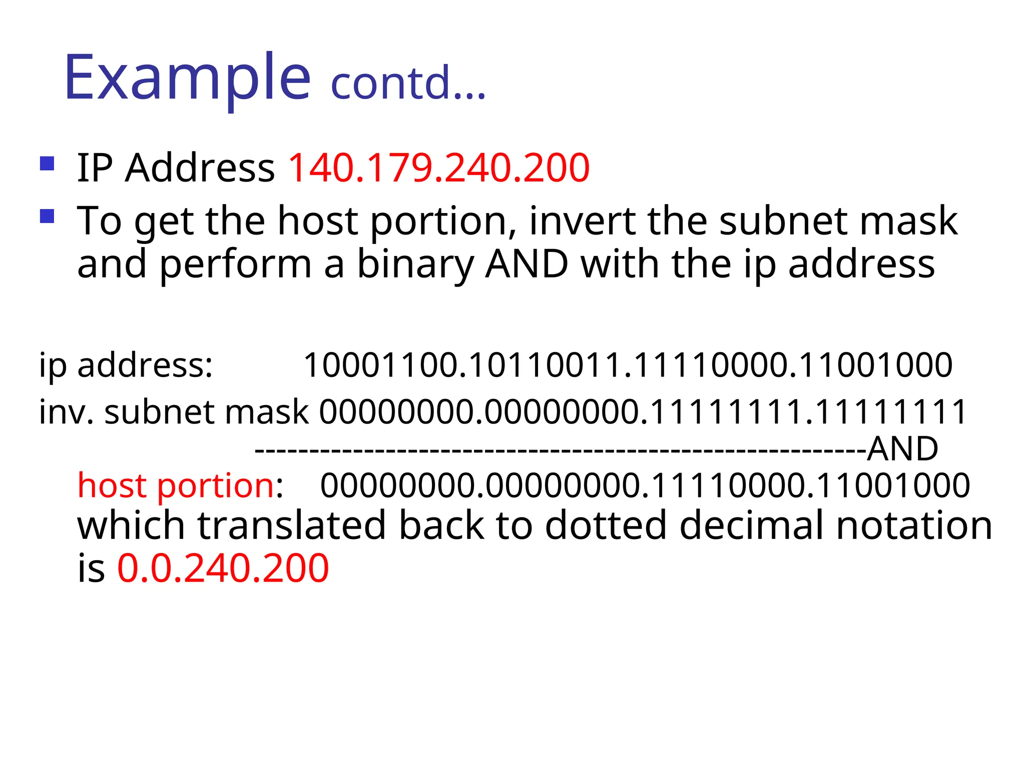
IP Address140.179.240.200
To get the host portion, invert the subnet mask
and perform a binary AND with the ip address
ip address: 10001100.10110011.11110000.11001000
inv. subnet mask 00000000.00000000.11111111.11111111
--------------------------------------------------------AND
host portion: 00000000.00000000.11110000.11001000
which translated back to dotted decimal notation
is 0.0.240.200
Example contd…
73.
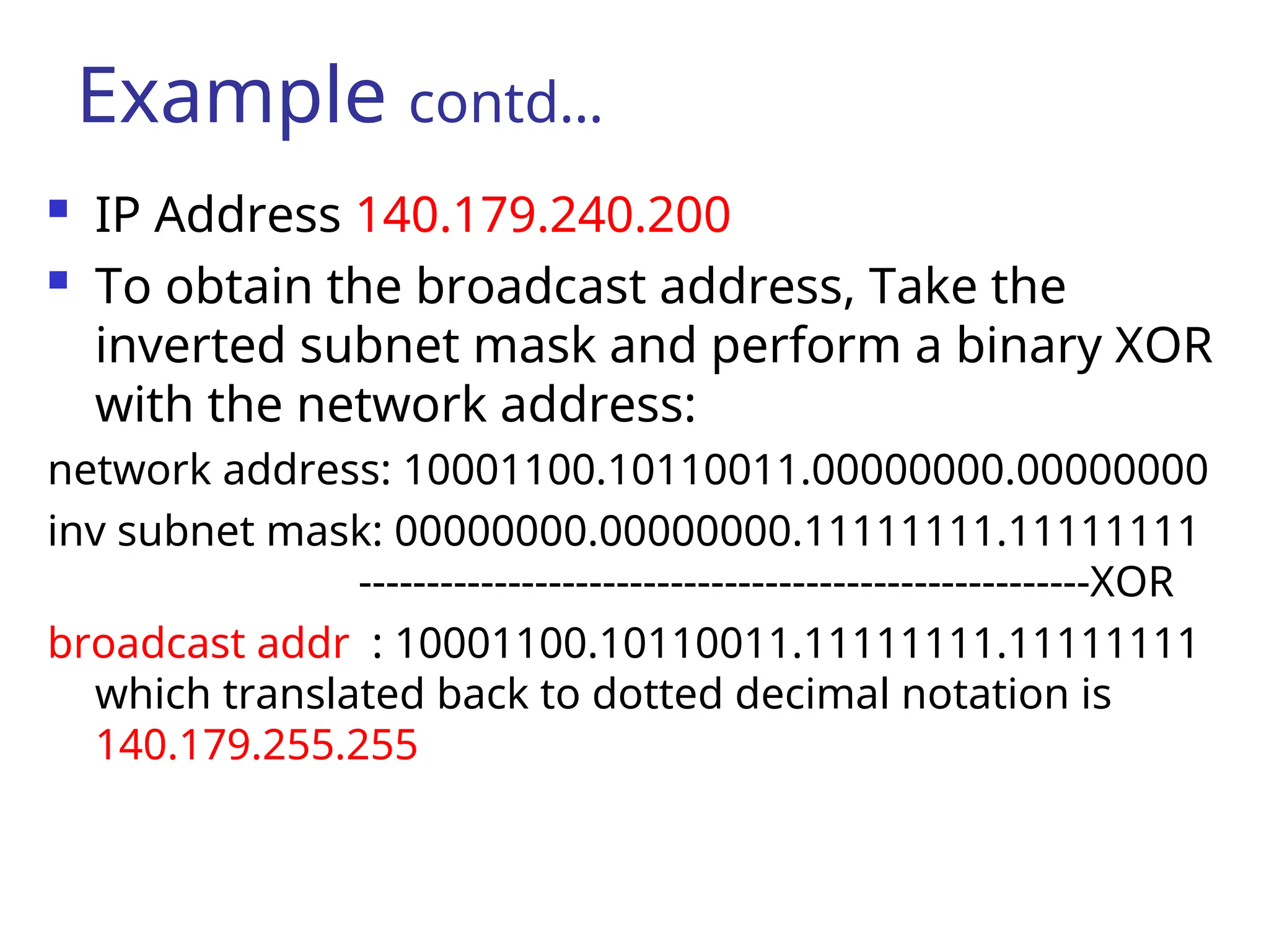
IP Address140.179.240.200
To obtain the broadcast address, Take the
inverted subnet mask and perform a binary XOR
with the network address:
network address: 10001100.10110011.00000000.00000000
inv subnet mask: 00000000.00000000.11111111.11111111
------------------------------------------------------XOR
broadcast addr : 10001100.10110011.11111111.11111111
which translated back to dotted decimal notation is
140.179.255.255
Example contd…
74.
74
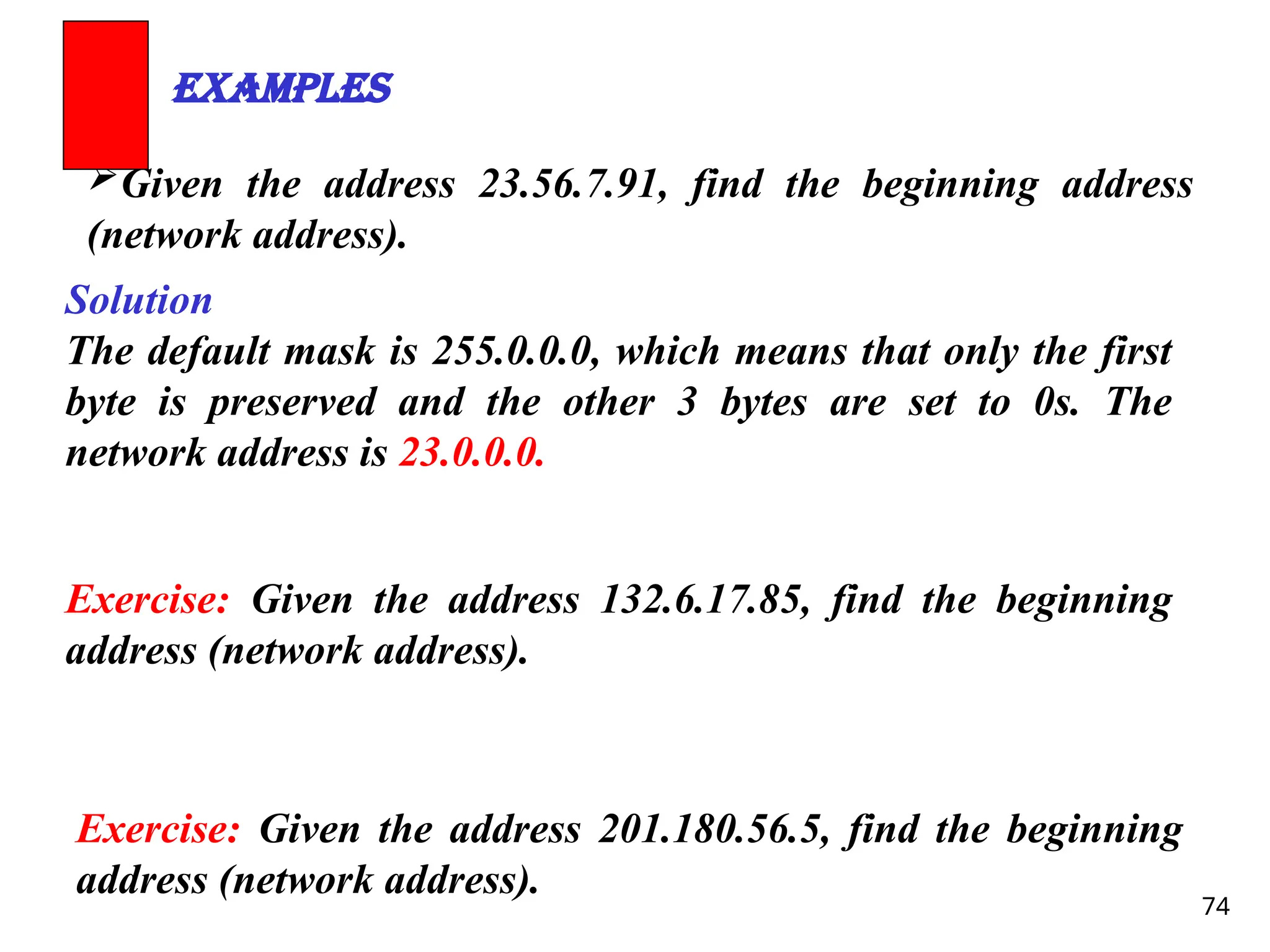
Given the address23.56.7.91, find the beginning address
(network address).
Examples
Solution
The default mask is 255.0.0.0, which means that only the first
byte is preserved and the other 3 bytes are set to 0s. The
network address is 23.0.0.0.
Exercise: Given the address 132.6.17.85, find the beginning
address (network address).
Exercise: Given the address 201.180.56.5, find the beginning
address (network address).
75.
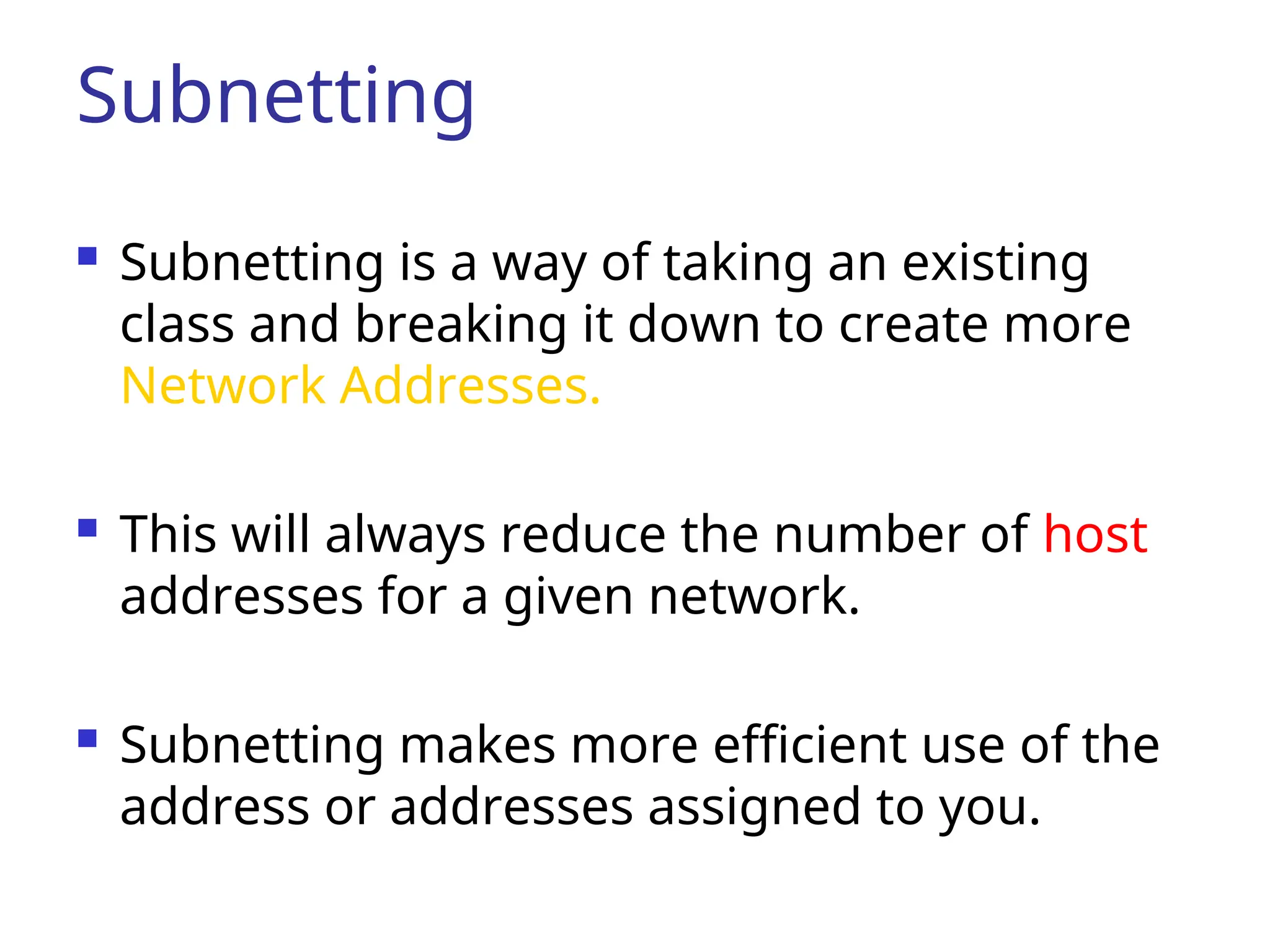
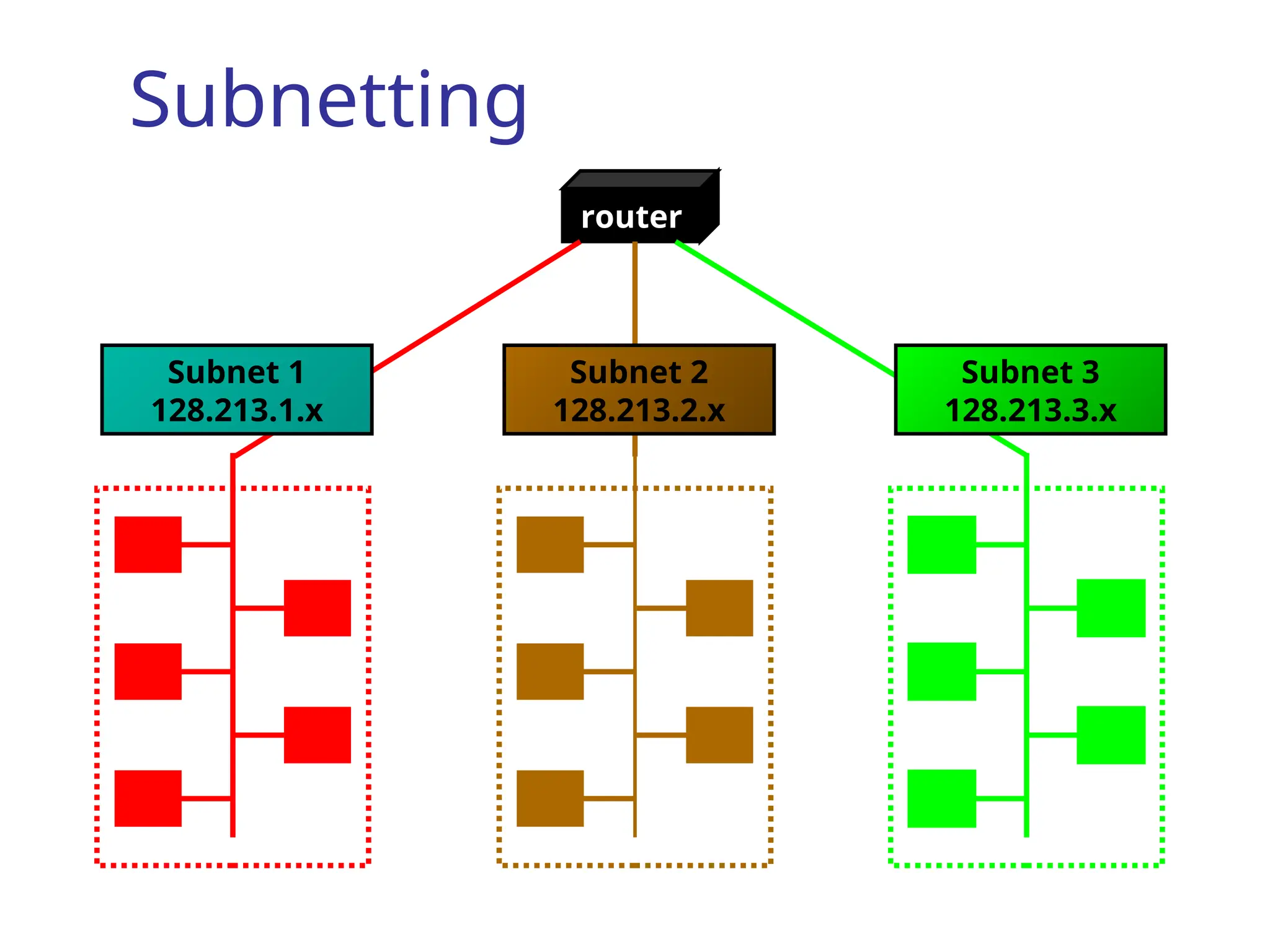
Subnetting
Subnetting isa way of taking an existing
class and breaking it down to create more
Network Addresses.
This will always reduce the number of host
addresses for a given network.
Subnetting makes more efficient use of the
address or addresses assigned to you.
79
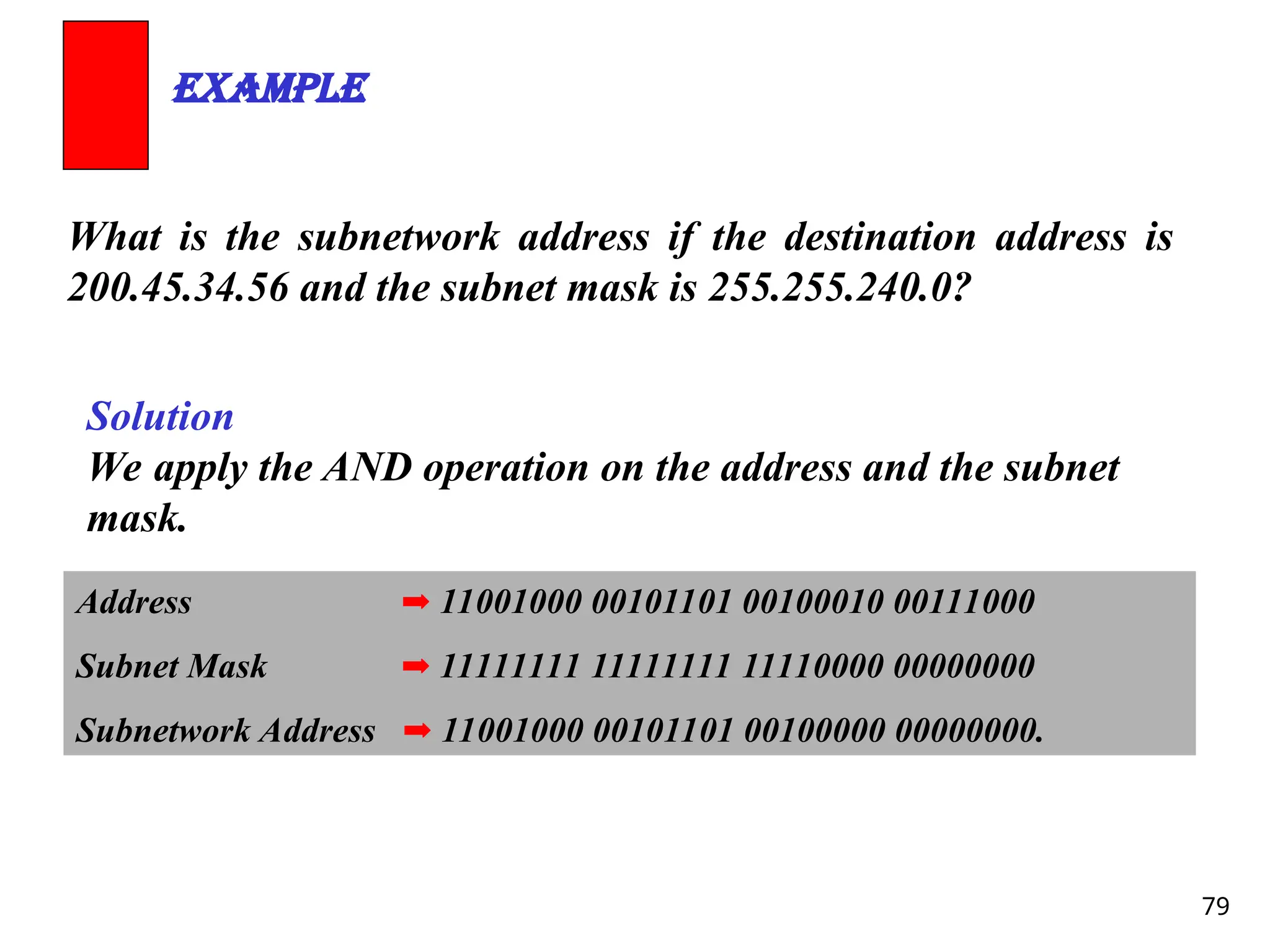
What is thesubnetwork address if the destination address is
200.45.34.56 and the subnet mask is 255.255.240.0?
Example
Solution
We apply the AND operation on the address and the subnet
mask.
Address ➡ 11001000 00101101 00100010 00111000
Subnet Mask ➡ 11111111 11111111 11110000 00000000
Subnetwork Address ➡ 11001000 00101101 00100000 00000000.
How many bitsto borrow?
First, you need to know how many bits
you have to work with.
Second, you must know either how
many subnets you need or how many
hosts per subnet you need.
Finally, you need to figure out the
number of bits to borrow.
82.
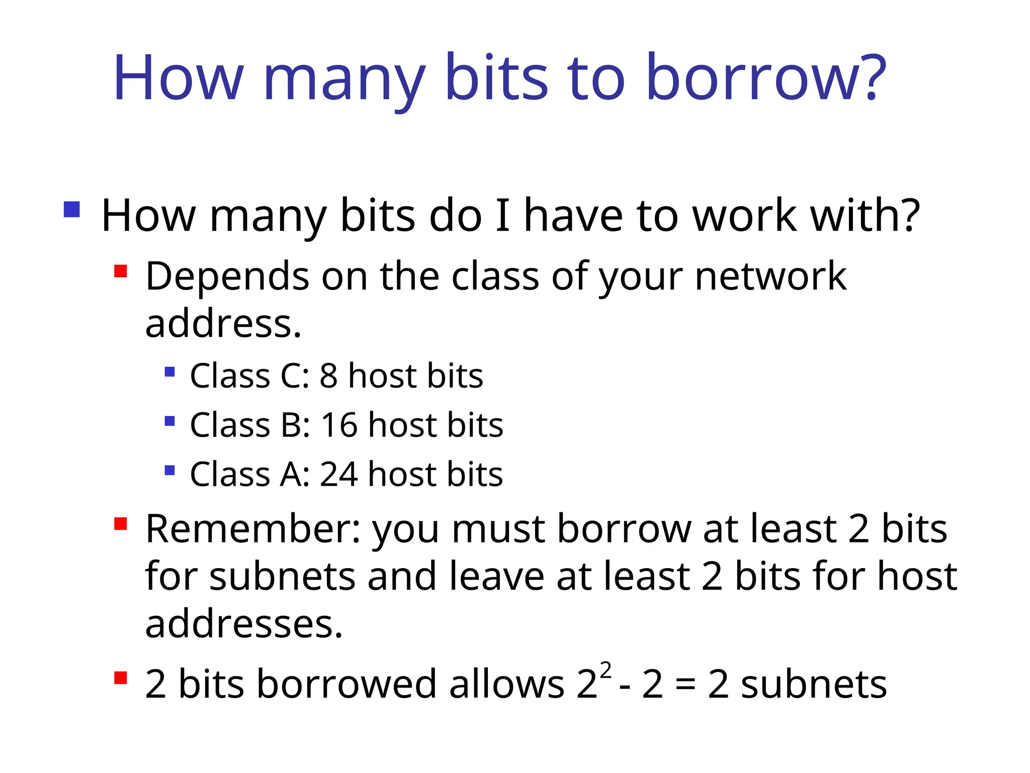
How many bitsto borrow?
How many bits do I have to work with?
Depends on the class of your network
address.
Class C: 8 host bits
Class B: 16 host bits
Class A: 24 host bits
Remember: you must borrow at least 2 bits
for subnets and leave at least 2 bits for host
addresses.
2 bits borrowed allows 22
- 2 = 2 subnets
83.
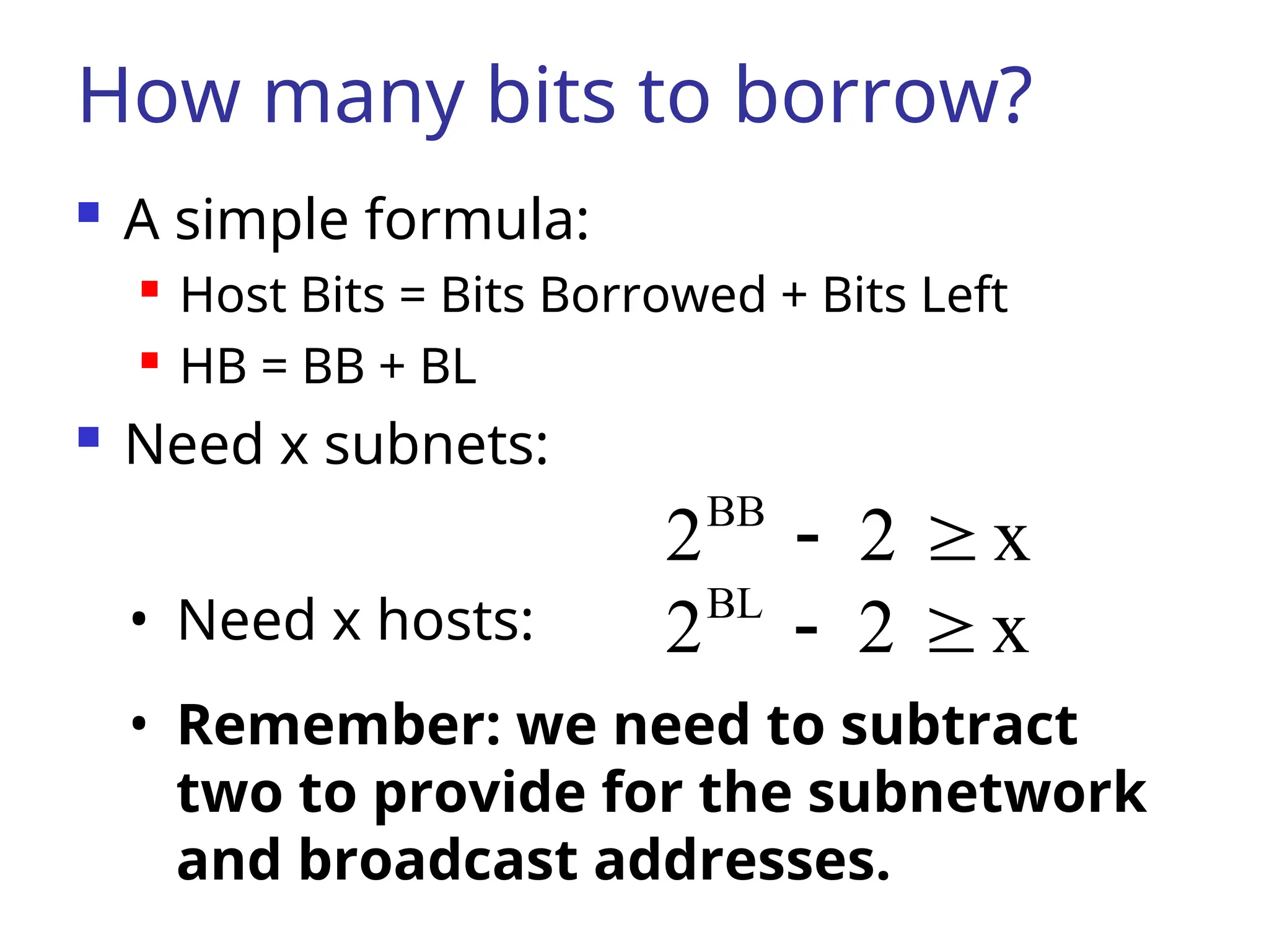
How many bitsto borrow?
A simple formula:
Host Bits = Bits Borrowed + Bits Left
HB = BB + BL
Need x subnets:
x
2
2BB
• Need x hosts: x
2
2BL
• Remember: we need to subtract
two to provide for the subnetwork
and broadcast addresses.
84.
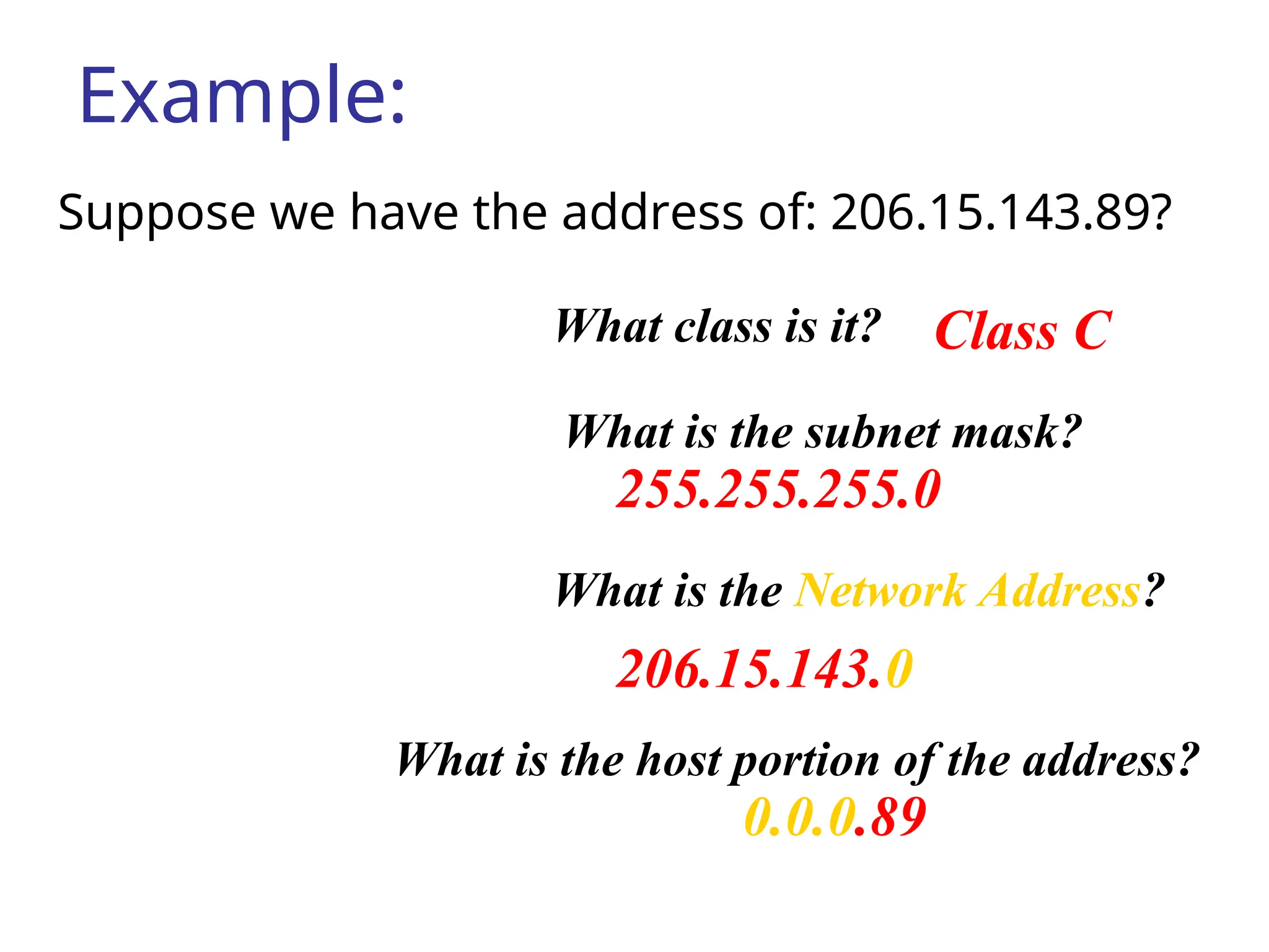
Example:
Suppose we havethe address of: 206.15.143.89?
Class C
255.255.255.0
206.15.143.0
0.0.0.89
What class is it?
What is the subnet mask?
What is the Network Address?
What is the host portion of the address?
85.
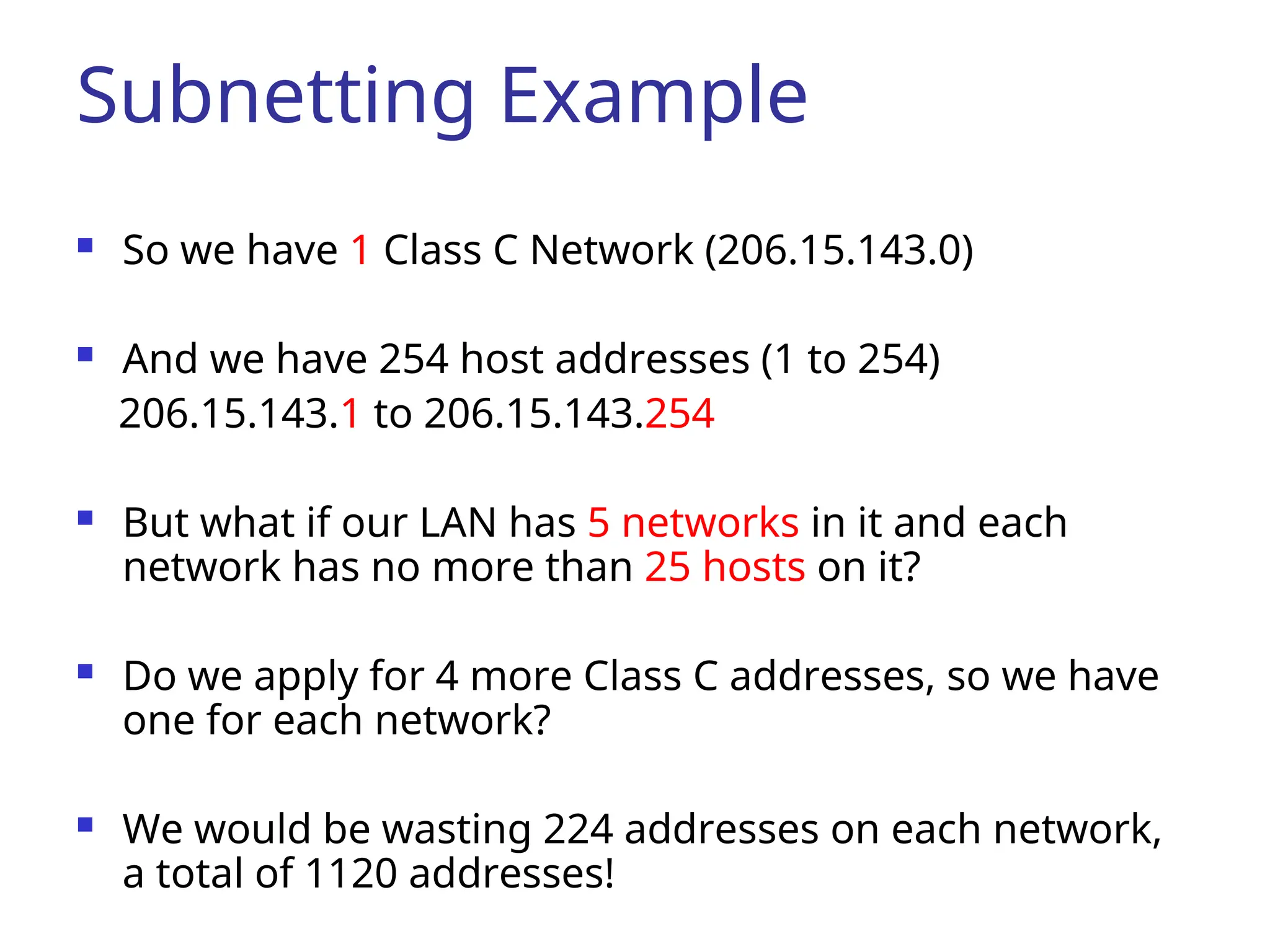
Subnetting Example
Sowe have 1 Class C Network (206.15.143.0)
And we have 254 host addresses (1 to 254)
206.15.143.1 to 206.15.143.254
But what if our LAN has 5 networks in it and each
network has no more than 25 hosts on it?
Do we apply for 4 more Class C addresses, so we have
one for each network?
We would be wasting 224 addresses on each network,
a total of 1120 addresses!
86.
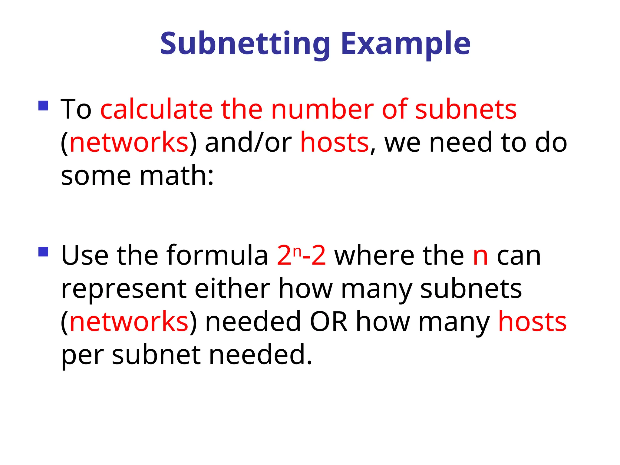
To calculatethe number of subnets
(networks) and/or hosts, we need to do
some math:
Use the formula 2n
-2 where the n can
represent either how many subnets
(networks) needed OR how many hosts
per subnet needed.
Subnetting Example
87.
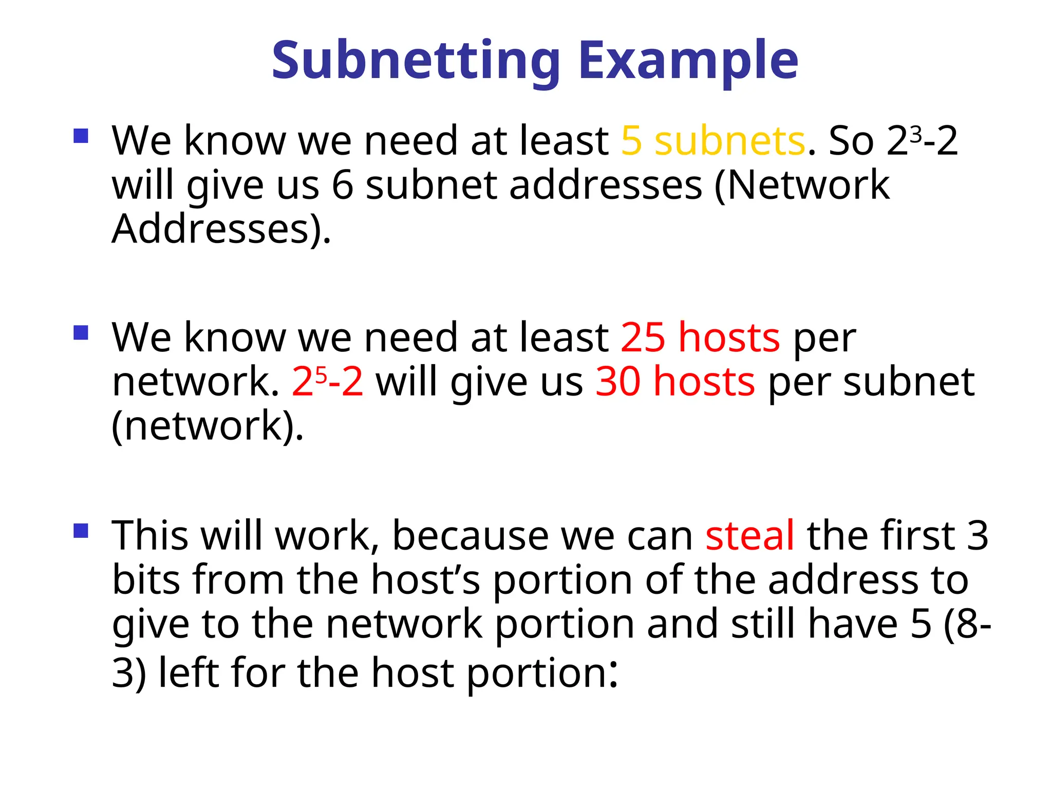
We knowwe need at least 5 subnets. So 23
-2
will give us 6 subnet addresses (Network
Addresses).
We know we need at least 25 hosts per
network. 25
-2 will give us 30 hosts per subnet
(network).
This will work, because we can steal the first 3
bits from the host’s portion of the address to
give to the network portion and still have 5 (8-
3) left for the host portion:
Subnetting Example
88.
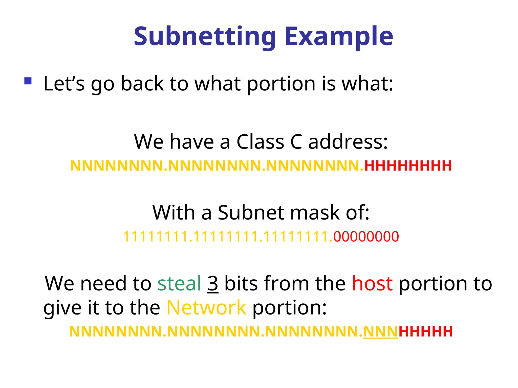
Let’s goback to what portion is what:
We have a Class C address:
NNNNNNNN.NNNNNNNN.NNNNNNNN.HHHHHHHH
With a Subnet mask of:
11111111.11111111.11111111.00000000
We need to steal 3 bits from the host portion to
give it to the Network portion:
NNNNNNNN.NNNNNNNN.NNNNNNNN.NNNHHHHH
Subnetting Example
89.
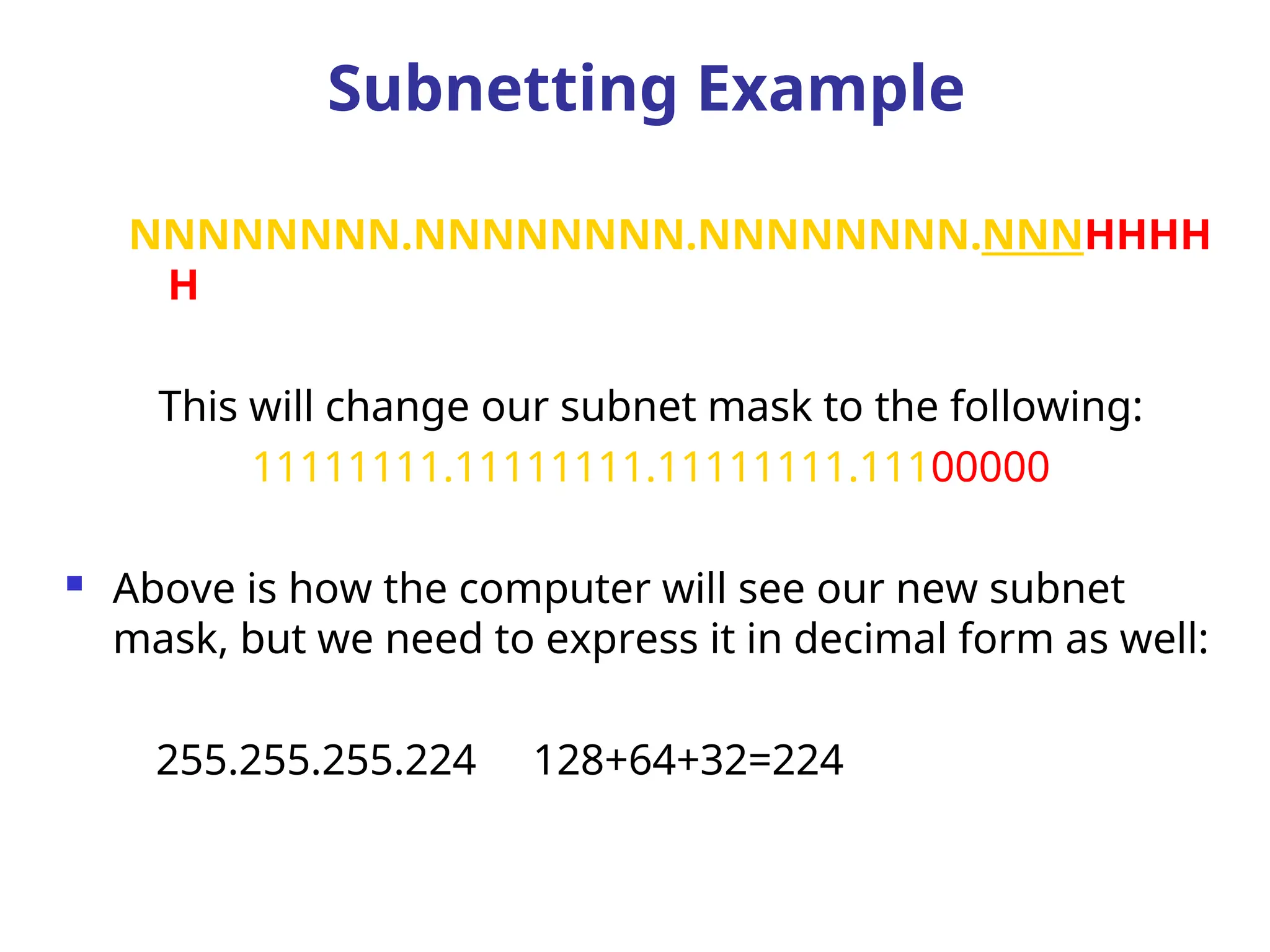
NNNNNNNN.NNNNNNNN.NNNNNNNN.NNNHHHH
H
This will changeour subnet mask to the following:
11111111.11111111.11111111.11100000
Above is how the computer will see our new subnet
mask, but we need to express it in decimal form as well:
255.255.255.224 128+64+32=224
Subnetting Example
90.
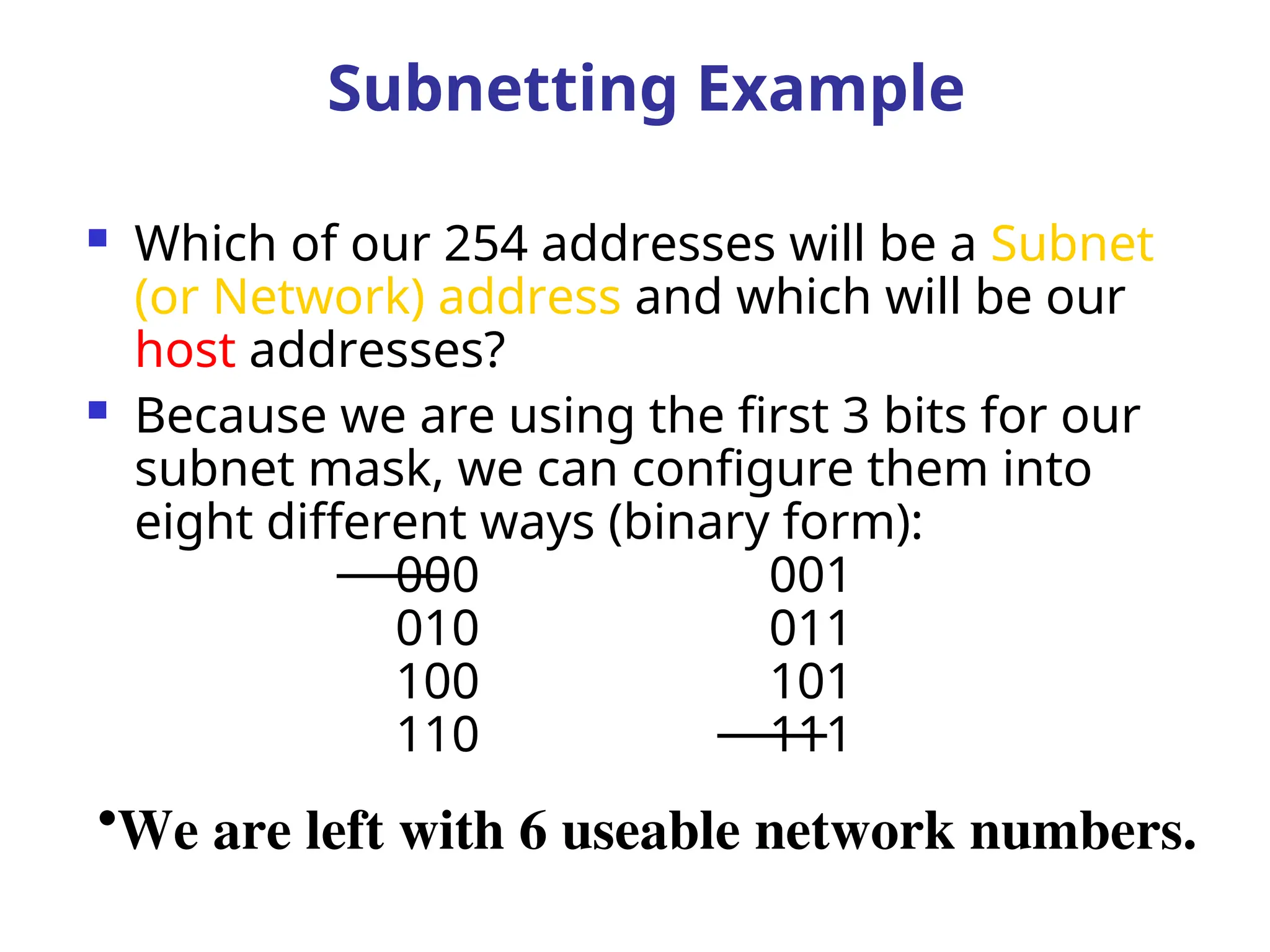
Which ofour 254 addresses will be a Subnet
(or Network) address and which will be our
host addresses?
Because we are using the first 3 bits for our
subnet mask, we can configure them into
eight different ways (binary form):
000 001
010 011
100 101
110 111
•We are left with 6 useable network numbers.
Subnetting Example
91.
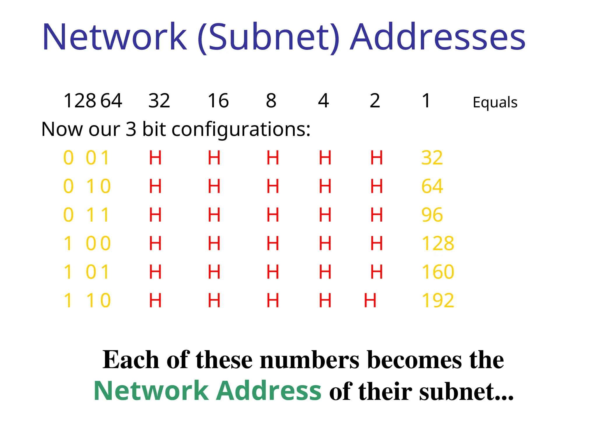
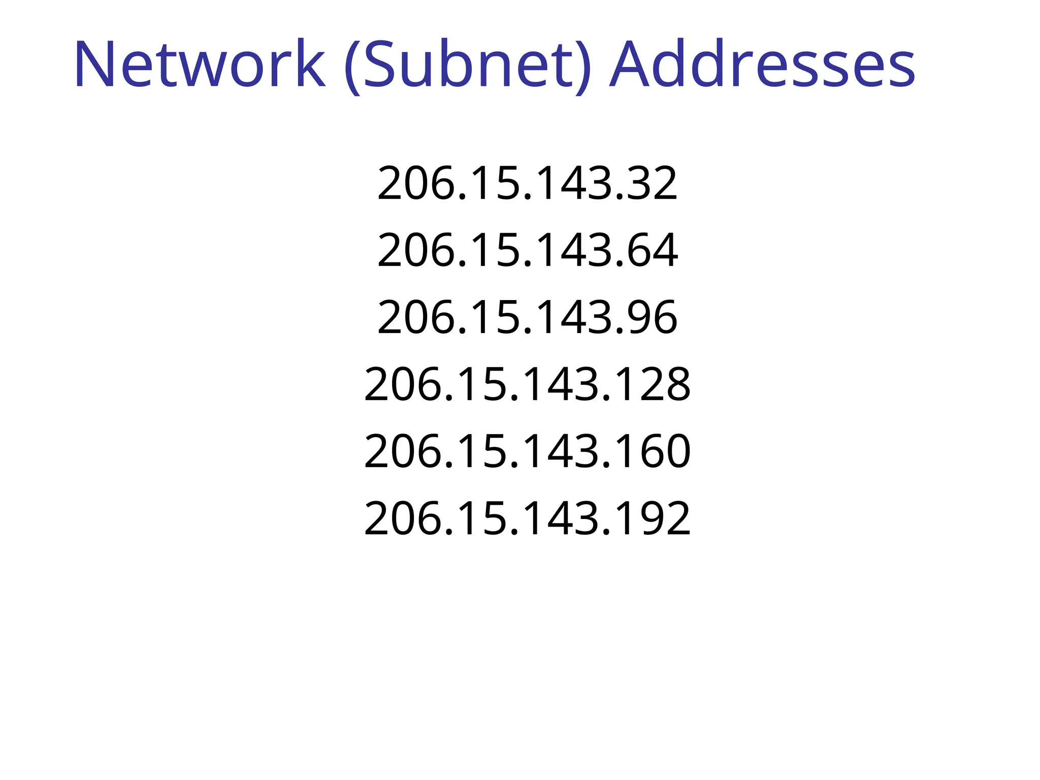
Network (Subnet) Addresses
12864 32 16 8 4 2 1 Equals
Now our 3 bit configurations:
0 0 1 H H H H H 32
0 1 0 H H H H H 64
0 1 1 H H H H H 96
1 0 0 H H H H H 128
1 0 1 H H H H H 160
1 1 0 H H H H H 192
Each of these numbers becomes the
Network Address of their subnet...
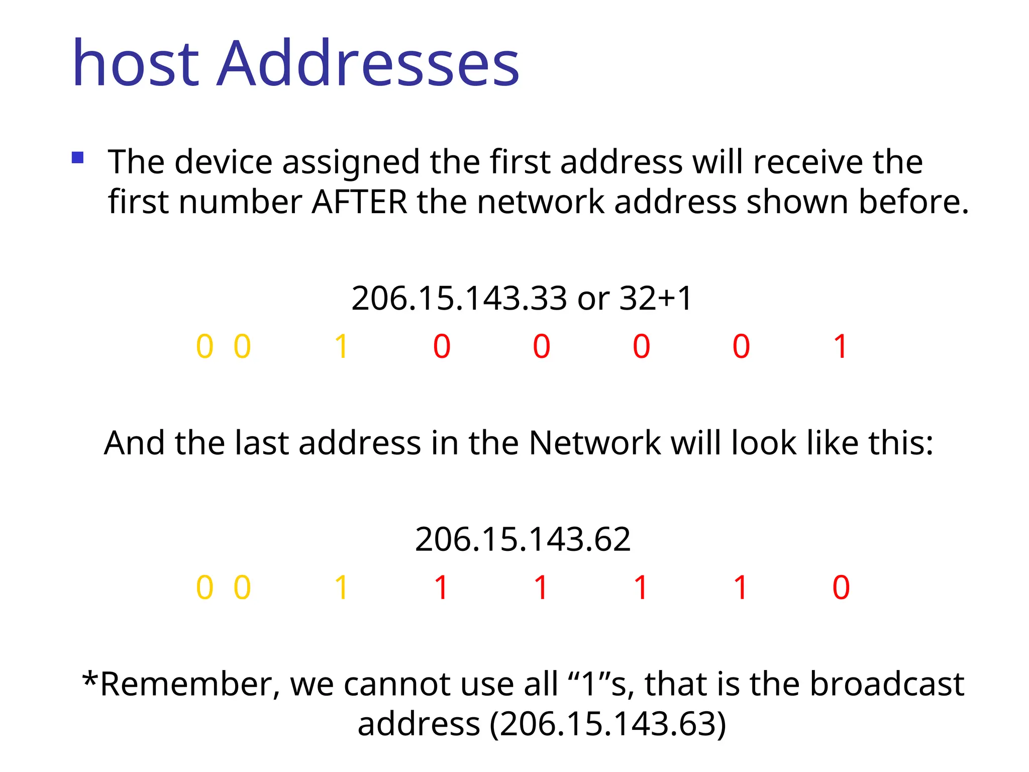
host Addresses
Thedevice assigned the first address will receive the
first number AFTER the network address shown before.
206.15.143.33 or 32+1
0 0 1 0 0 0 0 1
And the last address in the Network will look like this:
206.15.143.62
0 0 1 1 1 1 1 0
*Remember, we cannot use all “1”s, that is the broadcast
address (206.15.143.63)
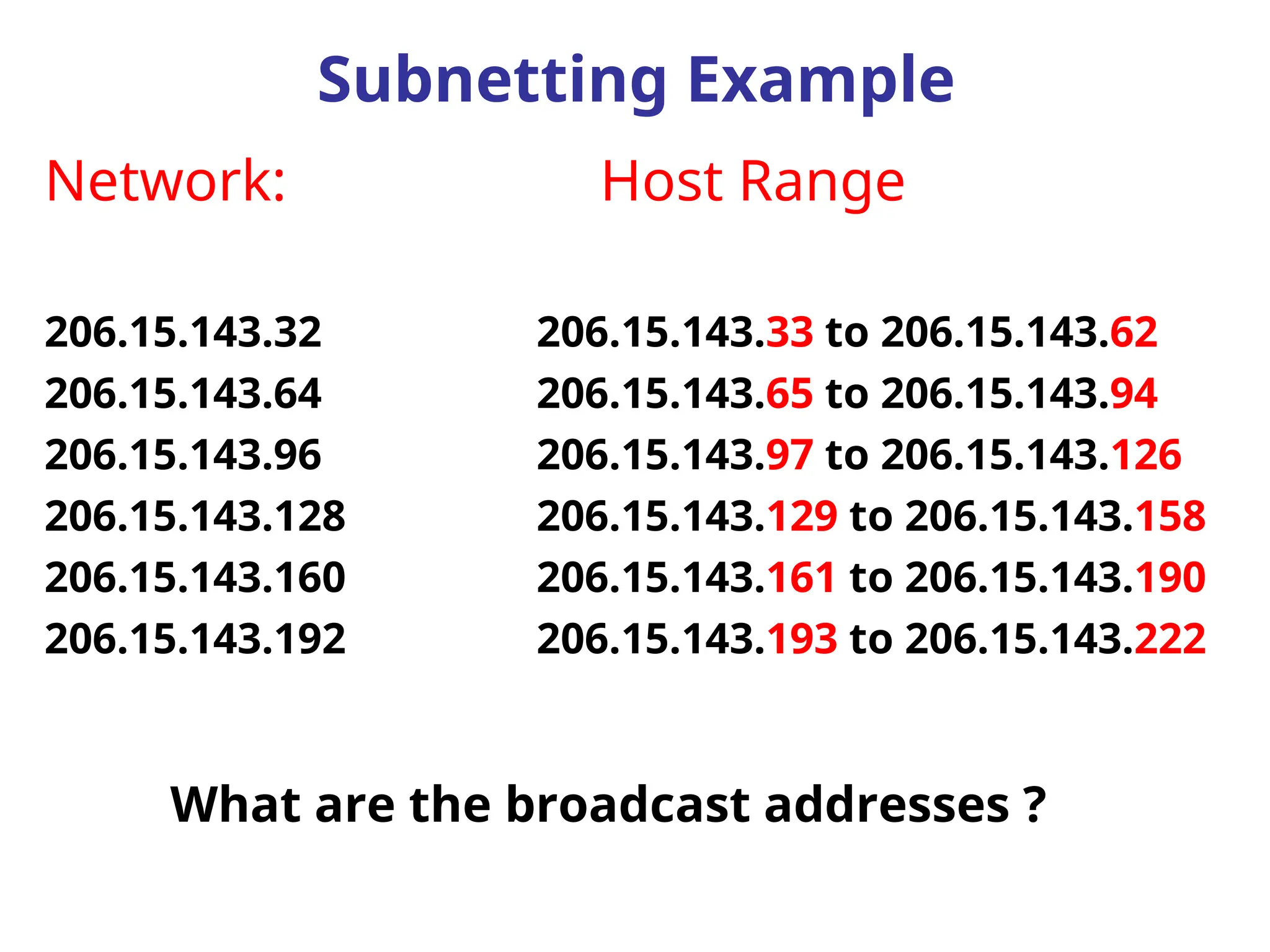
94.
Network: Host Range
206.15.143.32206.15.143.33 to 206.15.143.62
206.15.143.64 206.15.143.65 to 206.15.143.94
206.15.143.96 206.15.143.97 to 206.15.143.126
206.15.143.128 206.15.143.129 to 206.15.143.158
206.15.143.160 206.15.143.161 to 206.15.143.190
206.15.143.192 206.15.143.193 to 206.15.143.222
Subnetting Example
What are the broadcast addresses ?
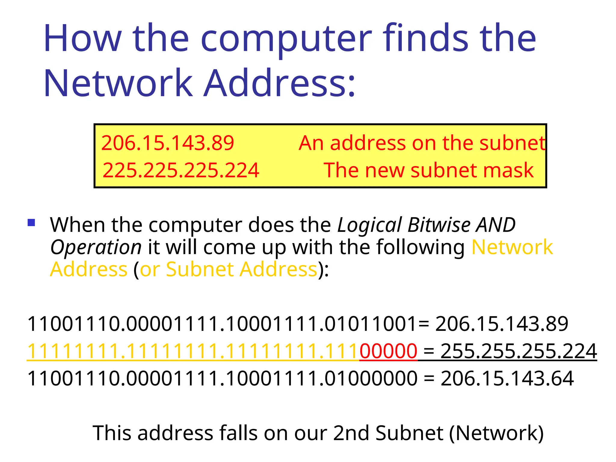
95.
How the computerfinds the
Network Address:
206.15.143.89 An address on the subnet
225.225.225.224 The new subnet mask
When the computer does the Logical Bitwise AND
Operation it will come up with the following Network
Address (or Subnet Address):
11001110.00001111.10001111.01011001= 206.15.143.89
11111111.11111111.11111111.11100000 = 255.255.255.224
11001110.00001111.10001111.01000000 = 206.15.143.64
This address falls on our 2nd Subnet (Network)
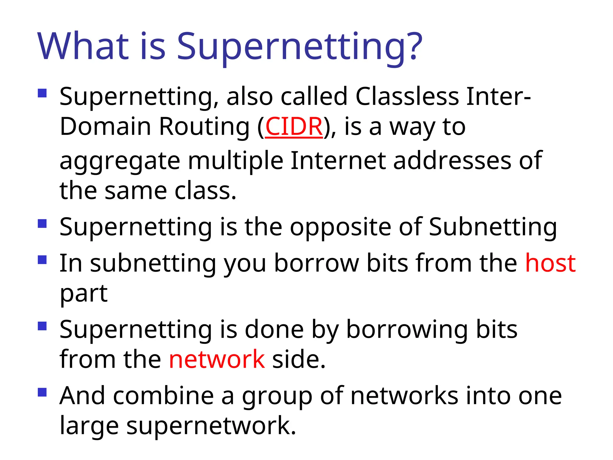
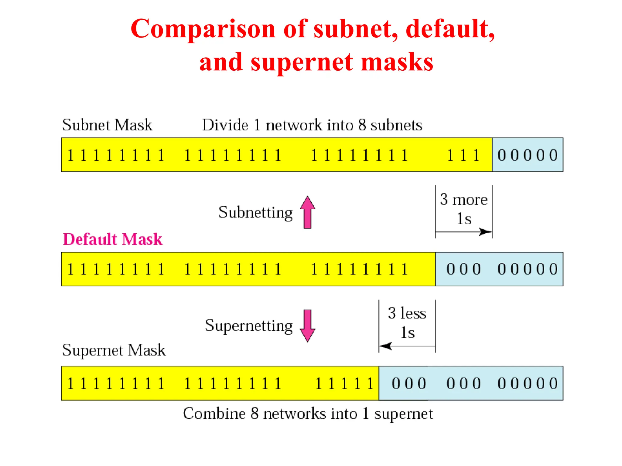
What is Supernetting?
Supernetting, also called Classless Inter-
Domain Routing (CIDR), is a way to
aggregate multiple Internet addresses of
the same class.
Supernetting is the opposite of Subnetting
In subnetting you borrow bits from the host
part
Supernetting is done by borrowing bits
from the network side.
And combine a group of networks into one
large supernetwork.
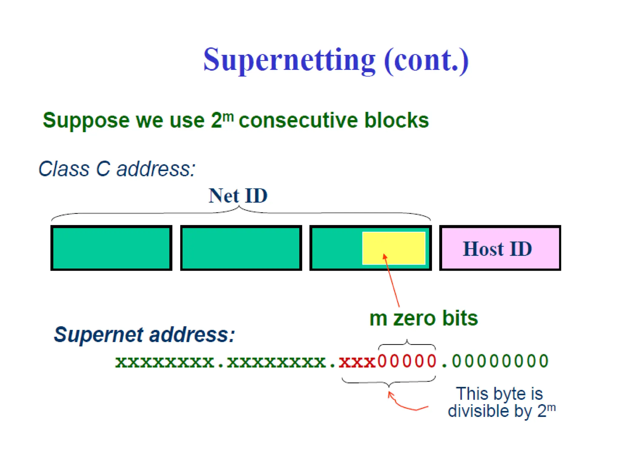
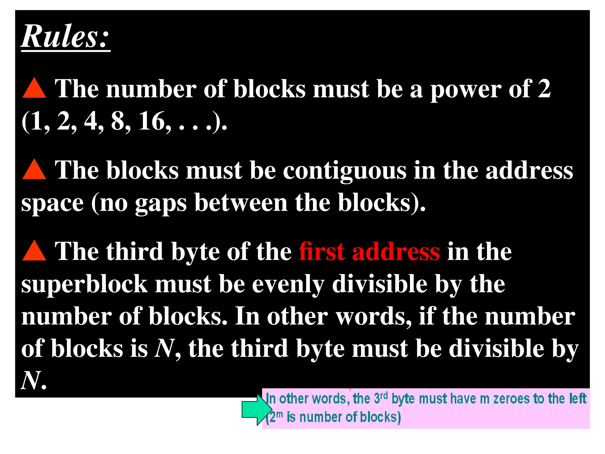
Rules:
The numberof blocks must be a power of 2
(1, 2, 4, 8, 16, . . .).
The blocks must be contiguous in the address
space (no gaps between the blocks).
The third byte of the first address in the
superblock must be evenly divisible by the
number of blocks. In other words, if the number
of blocks is N, the third byte must be divisible by
N.
104.
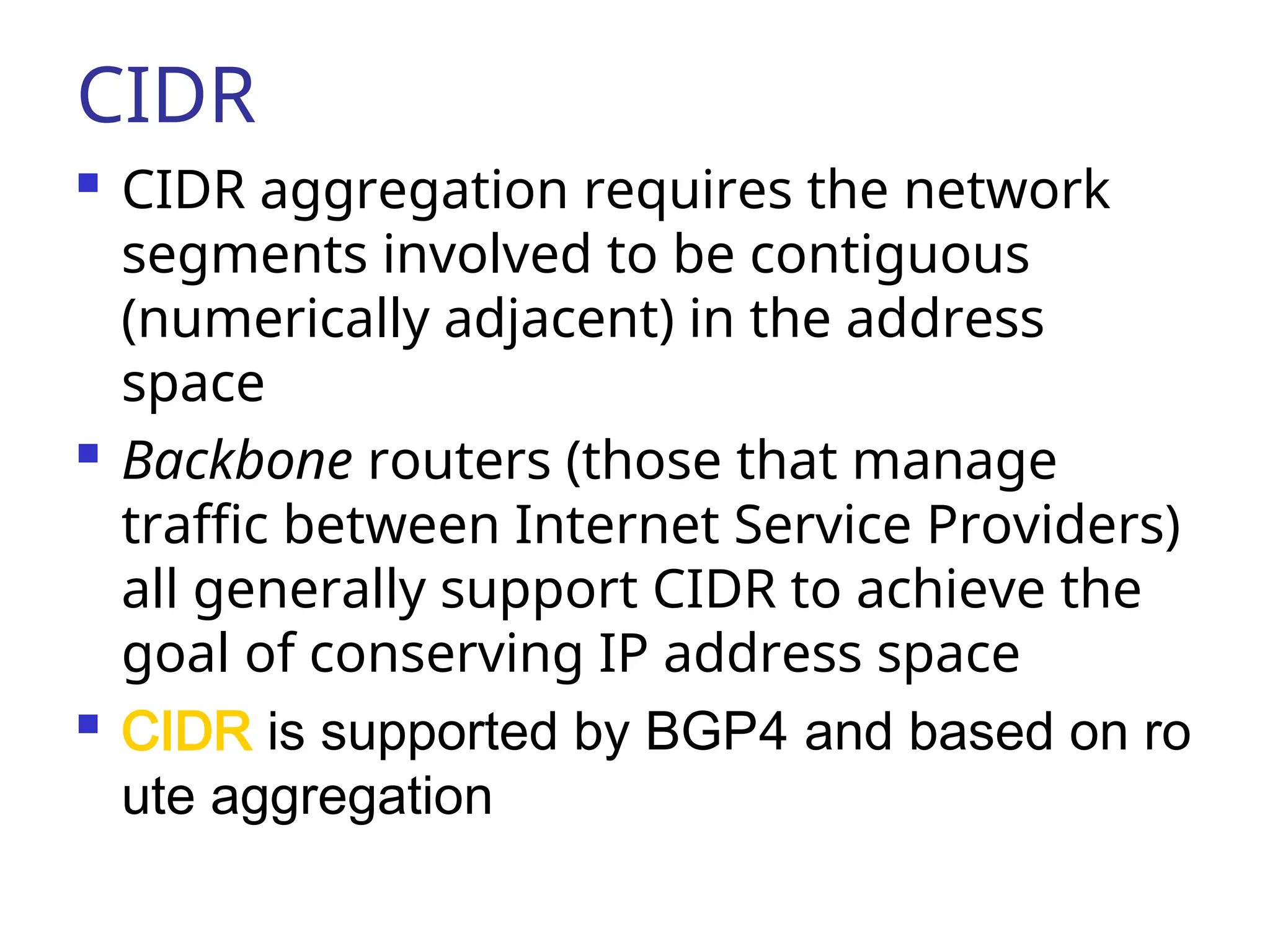
CIDR
CIDR aggregationrequires the network
segments involved to be contiguous
(numerically adjacent) in the address
space
Backbone routers (those that manage
traffic between Internet Service Providers)
all generally support CIDR to achieve the
goal of conserving IP address space
CIDR is supported by BGP4 and based on ro
ute aggregation
107.
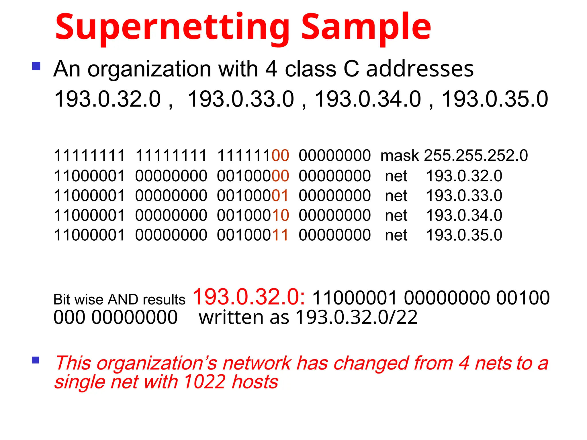
Supernetting Sample
Anorganization with 4 class C addresses
193.0.32.0 , 193.0.33.0 , 193.0.34.0 , 193.0.35.0
11111111 11111111 11111100 00000000 mask 255.255.252.0
11000001 00000000 00100000 00000000 net 193.0.32.0
11000001 00000000 00100001 00000000 net 193.0.33.0
11000001 00000000 00100010 00000000 net 193.0.34.0
11000001 00000000 00100011 00000000 net 193.0.35.0
Bit wise AND results 193.0.32.0: 11000001 00000000 00100
000 00000000 written as 193.0.32.0/22
This organization’s network has changed from 4 nets to a
single net with 1022 hosts
Mapping IP Addressesto
Hardware Addresses
IP Addresses are not recognized by
hardware.
If we know the IP address of a host,
how do we find out the hardware
address ?
The process of finding the hardware
address of a host given the IP address
is called
Address Resolution
Address Resolution
110.
Reverse Address Resolution
The process of finding out the IP
address of a host given a
hardware address is called
Reverse Address Resolution
Reverse Address Resolution
111.
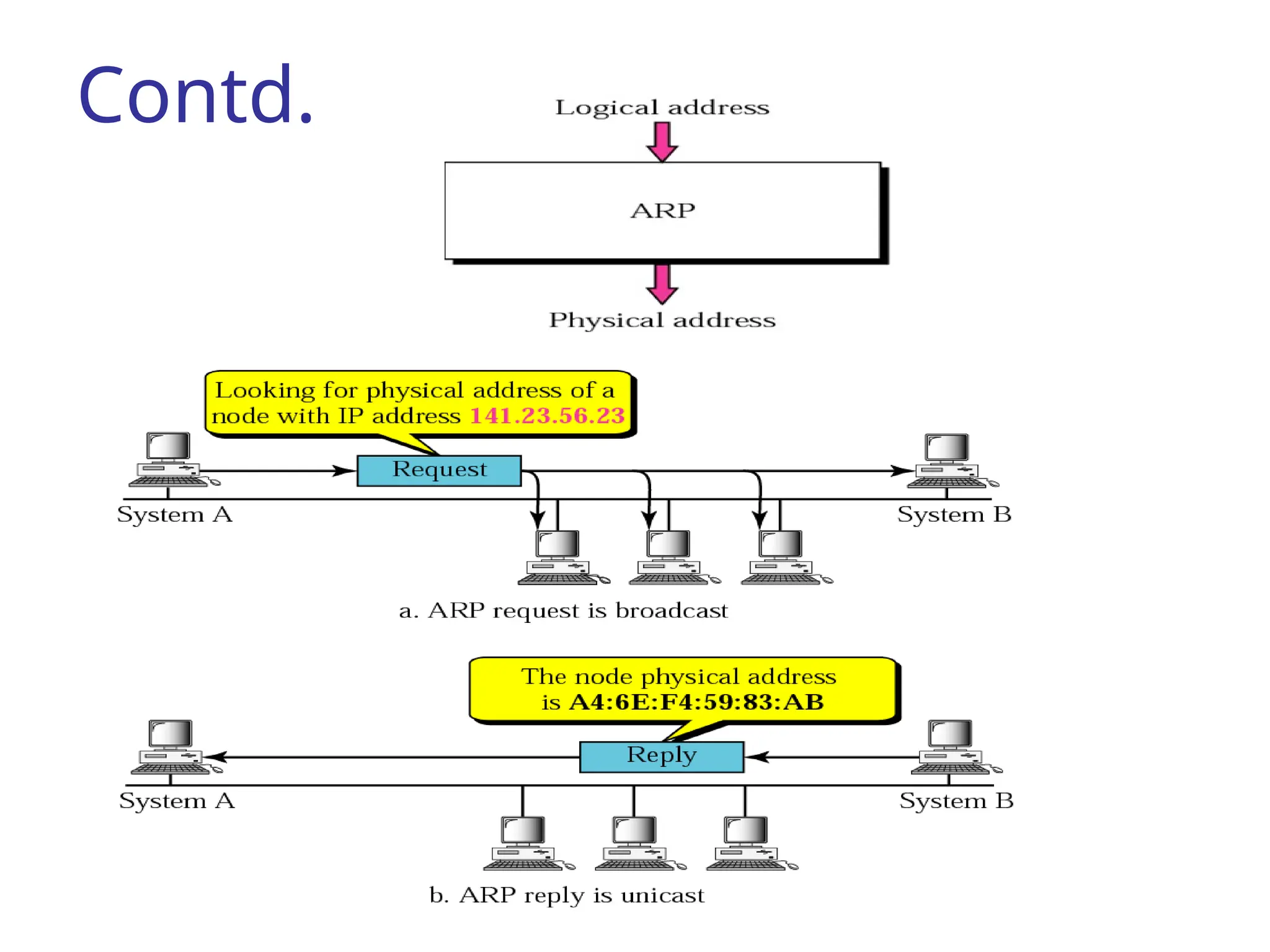
ARP
On atypical physical network, such as a LAN,
On a typical physical network, such as a LAN,
each device on a link is identified by a
each device on a link is identified by a
physical or station address that is usually
physical or station address that is usually
imprinted on the NIC.
imprinted on the NIC.
The Address Resolution Protocol is used by a
The Address Resolution Protocol is used by a
sending host when it knows the IP address of
sending host when it knows the IP address of
the destination but needs the Ethernet address.
the destination but needs the Ethernet address.
ARP is a broadcast protocol - every host on
ARP is a broadcast protocol - every host on
the network receives the request.
the network receives the request.
Each host checks the request against it’s IP
Each host checks the request against it’s IP
address - the right one responds.
address - the right one responds.
114
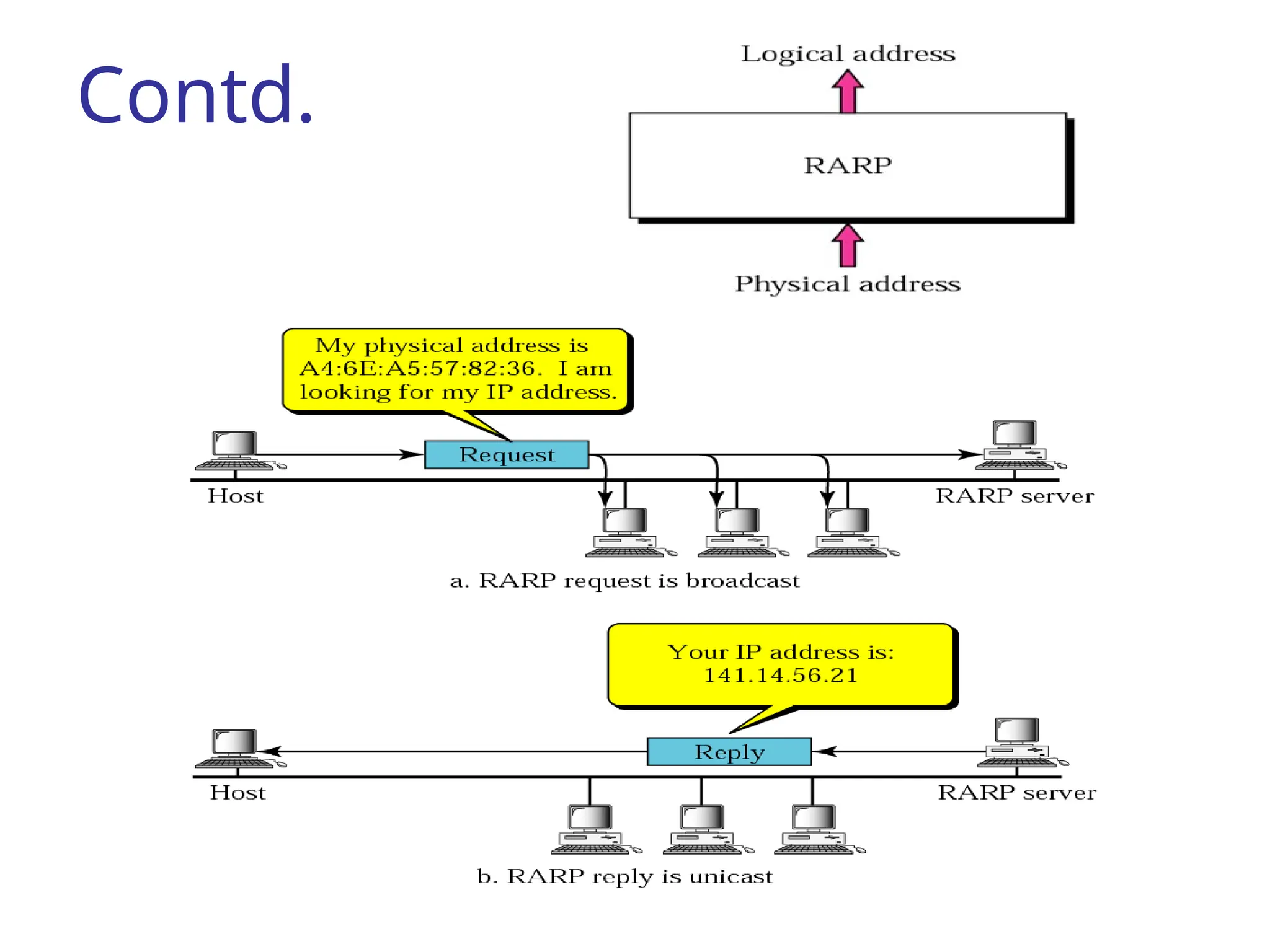
RARP
RARP finds thelogical address for a
RARP finds the logical address for a
machine that only knows its physical address.
machine that only knows its physical address.
The RARP request packets are
broadcast;
the RARP reply packets are unicast.
TCP/IP Protocol Suite116
DHCP
The Dynamic Host Configuration Protocol
The Dynamic Host Configuration Protocol
(DHCP) provides static and dynamic address
(DHCP) provides static and dynamic address
allocation that can be manual or automatic.
allocation that can be manual or automatic.
Dynamic Host Configuration Protocol
Dynamic Host Configuration Protocol
automates network-parameter assignment to
automates network-parameter assignment to
network devices from one or more
network devices from one or more
fault-tolerant DHCP servers.
DHCP servers.
Even in small networks, DHCP is useful
Even in small networks, DHCP is useful
because it can make it easy to add new
because it can make it easy to add new
machines to the network.
machines to the network.
117.
TCP/IP Protocol Suite117
Contd. DHCP
When a DHCP-configured client (a computer
When a DHCP-configured client (a computer
or any other network-aware device) connects to
or any other network-aware device) connects to
a network, the DHCP client sends a
a network, the DHCP client sends a broadcast
query requesting necessary information from a
query requesting necessary information from a
DHCP server.
DHCP server.
The DHCP server manages a pool of IP
The DHCP server manages a pool of IP
addresses and information about client
addresses and information about client
configuration parameters such as
configuration parameters such as
default gateway,
, domain name, the
, the
DNS servers, other servers such as
, other servers such as
time servers, and so forth
, and so forth
118.
TCP/IP Protocol Suite118
Contd. DHCP
On receiving a valid request, the server
On receiving a valid request, the server
assigns the computer an IP address, a lease
assigns the computer an IP address, a lease
(length of time the allocation is valid), and
(length of time the allocation is valid), and
other IP configuration parameters, such as the
other IP configuration parameters, such as the
subnet mask and the default gateway.
and the default gateway.
The query is typically initiated immediately
The query is typically initiated immediately
after booting, and must complete before the
after booting, and must complete before the
client can initiate IP-based communication with
client can initiate IP-based communication with
other hosts.
other hosts.
119.
TCP/IP Protocol Suite119
Contd. DHCP
Depending on implementation, the DHCP
Depending on implementation, the DHCP
server may have three methods of allocating IP-
server may have three methods of allocating IP-
addresses:
addresses:
Dynamic allocation
Automatic allocation
Static allocation
120.
TCP/IP Protocol Suite120
Dynamic allocation
A network administrator assigns a range of IP
A network administrator assigns a range of IP
addresses to DHCP, and each client computer
addresses to DHCP, and each client computer
on the LAN has its IP software configured to
on the LAN has its IP software configured to
request an IP address from the DHCP server
request an IP address from the DHCP server
during network initialization.
during network initialization.
The request-and-grant process uses a lease
The request-and-grant process uses a lease
concept with a controllable time period,
concept with a controllable time period,
allowing the DHCP server to reclaim (and then
allowing the DHCP server to reclaim (and then
reallocate) IP addresses that are not renewed
reallocate) IP addresses that are not renewed
(dynamic re-use of IP addresses).
(dynamic re-use of IP addresses).
121.
TCP/IP Protocol Suite121
Automatic allocation
The DHCP server permanently assigns a free
The DHCP server permanently assigns a free
IP address to a requesting client from the range
IP address to a requesting client from the range
defined by the administrator.
defined by the administrator.
This is like dynamic allocation, but the DHCP
This is like dynamic allocation, but the DHCP
server keeps a table of past IP address
server keeps a table of past IP address
assignments, so that it can preferentially assign
assignments, so that it can preferentially assign
to a client the same IP address that the client
to a client the same IP address that the client
previously had.
previously had.
122.
TCP/IP Protocol Suite122
Static allocation
The DHCP server allocates an IP address
The DHCP server allocates an IP address
based on a table with MAC address/IP address
based on a table with MAC address/IP address
pairs, which are manually filled in (perhaps by
pairs, which are manually filled in (perhaps by
a network administrator).
a network administrator).
Only requesting clients with a MAC address
Only requesting clients with a MAC address
listed in this table will be allocated an IP
listed in this table will be allocated an IP
address.
address.
123.
ICMP Internet ControlMessage Protocol
Is one of the protocols of the internet
protocol suite.
It is used by network devices, like routers.
When information is transferred over the
Internet, computer systems send and
receive data using the TCP/IP protocol.
If there is a problem with the connection,
error and status messages regarding the
connection are sent using ICMP, which is
part of the Internet protocol.
124.
ICMP Internet ControlMessage Protocol
ICMP is a protocol used for exchanging
control messages.
ICMP uses IP to deliver messages.
ICMP messages are usually generated
and processed by the IP software, not
the user process.
125.
ICMP Internet ControlMessage Protocol
Each ICMP message contains three fields that
define its purpose and provide a checksum.
They are TYPE, CODE, and CHECKSUM fields.
The TYPE field identifies the ICMP message,
the CODE field provides further information
about the associated TYPE field, and the
CHECKSUM provides a method for
determining the integrity of the message.
126.
UDP User DatagramProtocol
UDP is a transport-layer protocol
UDP (User Datagram Protocol) is a
communications protocol that offers a
limited amount of service when
messages are exchanged between
computers in a network that uses the
Internet Protocol (IP).
UDP uses IP to deliver datagrams to the
right host.
127.
UDP User DatagramProtocol
Unlike TCP, however, UDP does not provide
the service of dividing a message into
packets (datagrams) and reassembling it at
the other end.
Specifically, UDP doesn't provide sequencing
of the packets that the data arrives in.
This means that the application program
that uses UDP must be able to make sure
that the entire message has arrived and is in
the right order.
128.
Ports
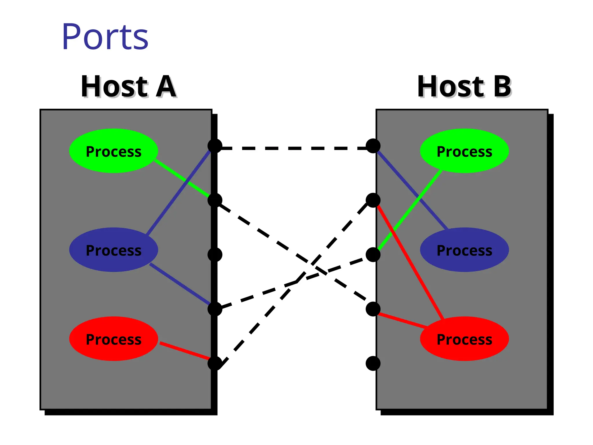
UDP/IP usesan abstract destination
point called a protocol port.
Ports are identified by a positive integer.
Operating systems provide some
mechanism that processes use to
specify a port.
129.
Ports
Host A
Host AHost B
Host B
Process
Process
Process
Process
Process
Process
130.
UDP
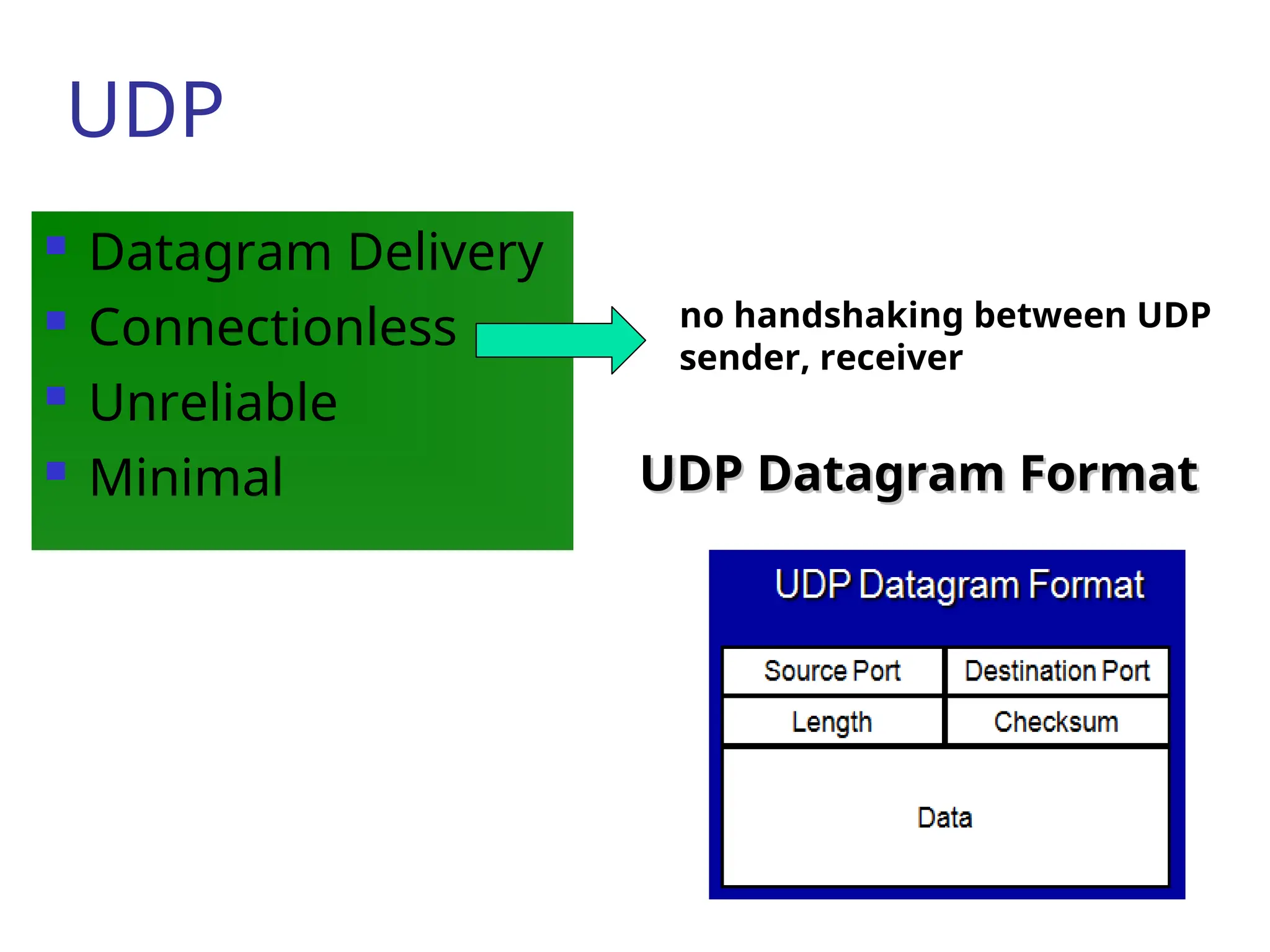
Datagram Delivery
Connectionless
Unreliable
Minimal UDP Datagram Format
UDP Datagram Format
no handshaking between UDP
sender, receiver
131.
TCP Transmission ControlProtocol
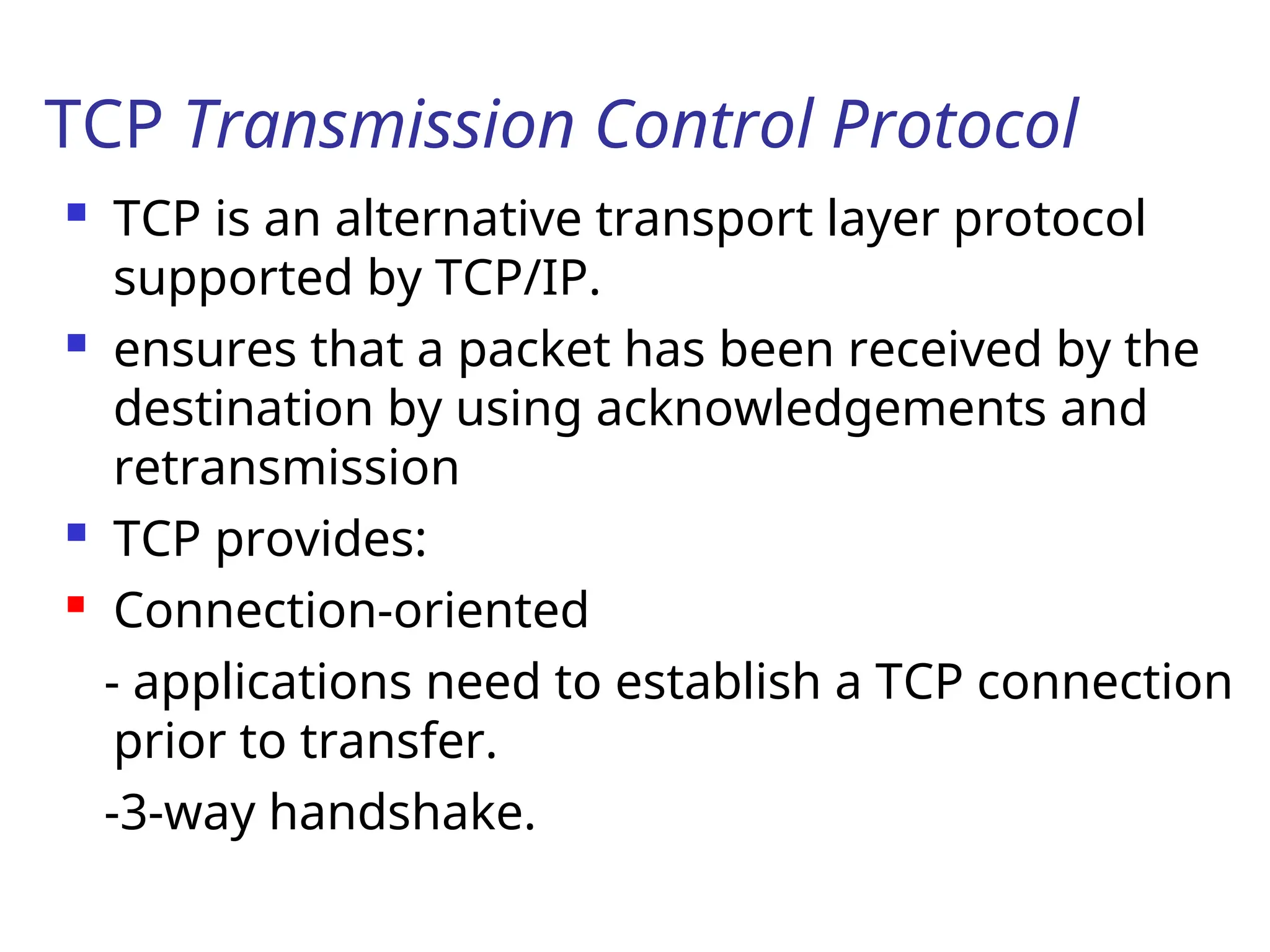
TCP is an alternative transport layer protocol
supported by TCP/IP.
ensures that a packet has been received by the
destination by using acknowledgements and
retransmission
TCP provides:
Connection-oriented
- applications need to establish a TCP connection
prior to transfer.
-3-way handshake.
132.
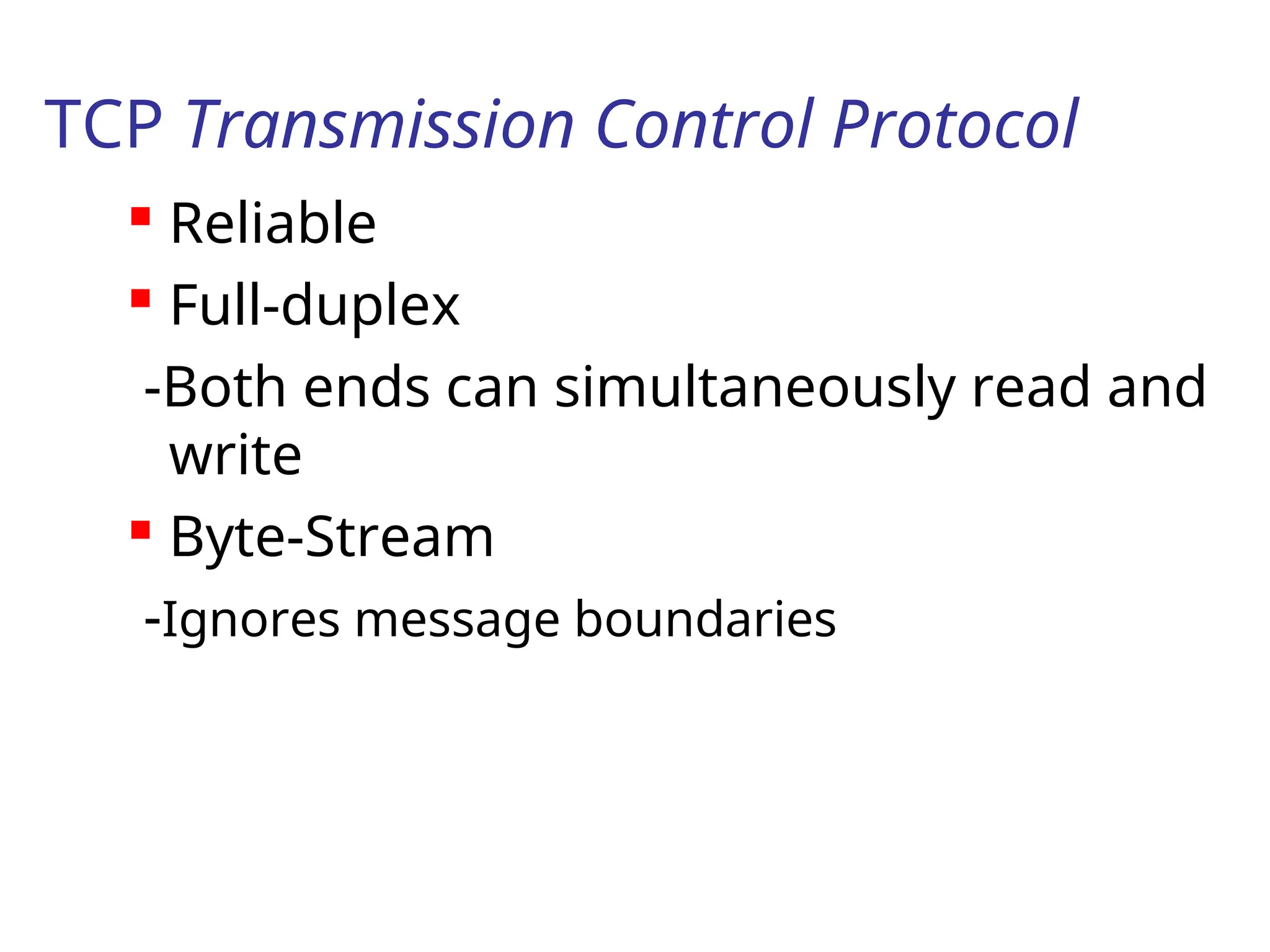
TCP Transmission ControlProtocol
Reliable
Full-duplex
-Both ends can simultaneously read and
write
Byte-Stream
-Ignores message boundaries
133.
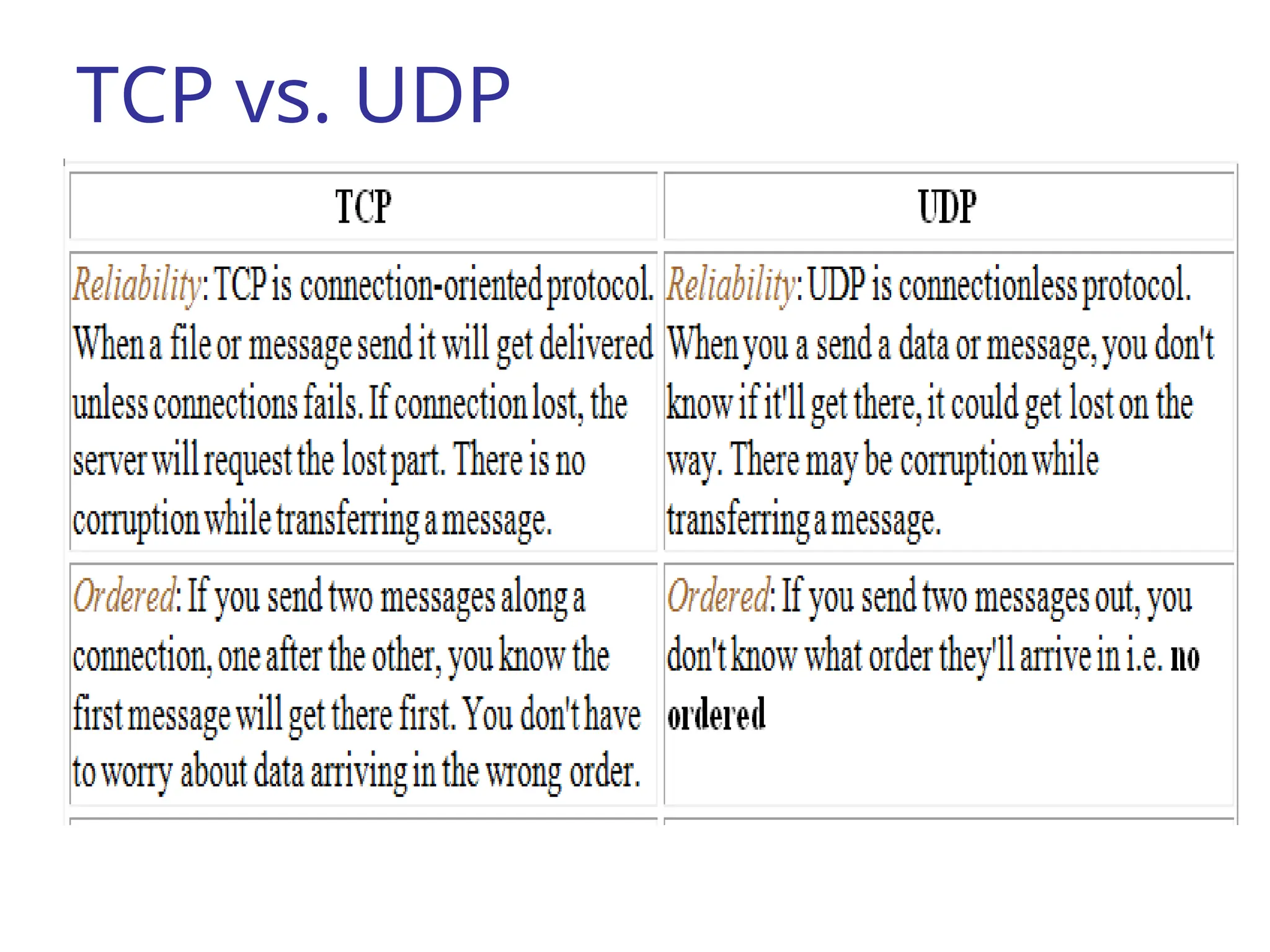
TCP vs. UDP
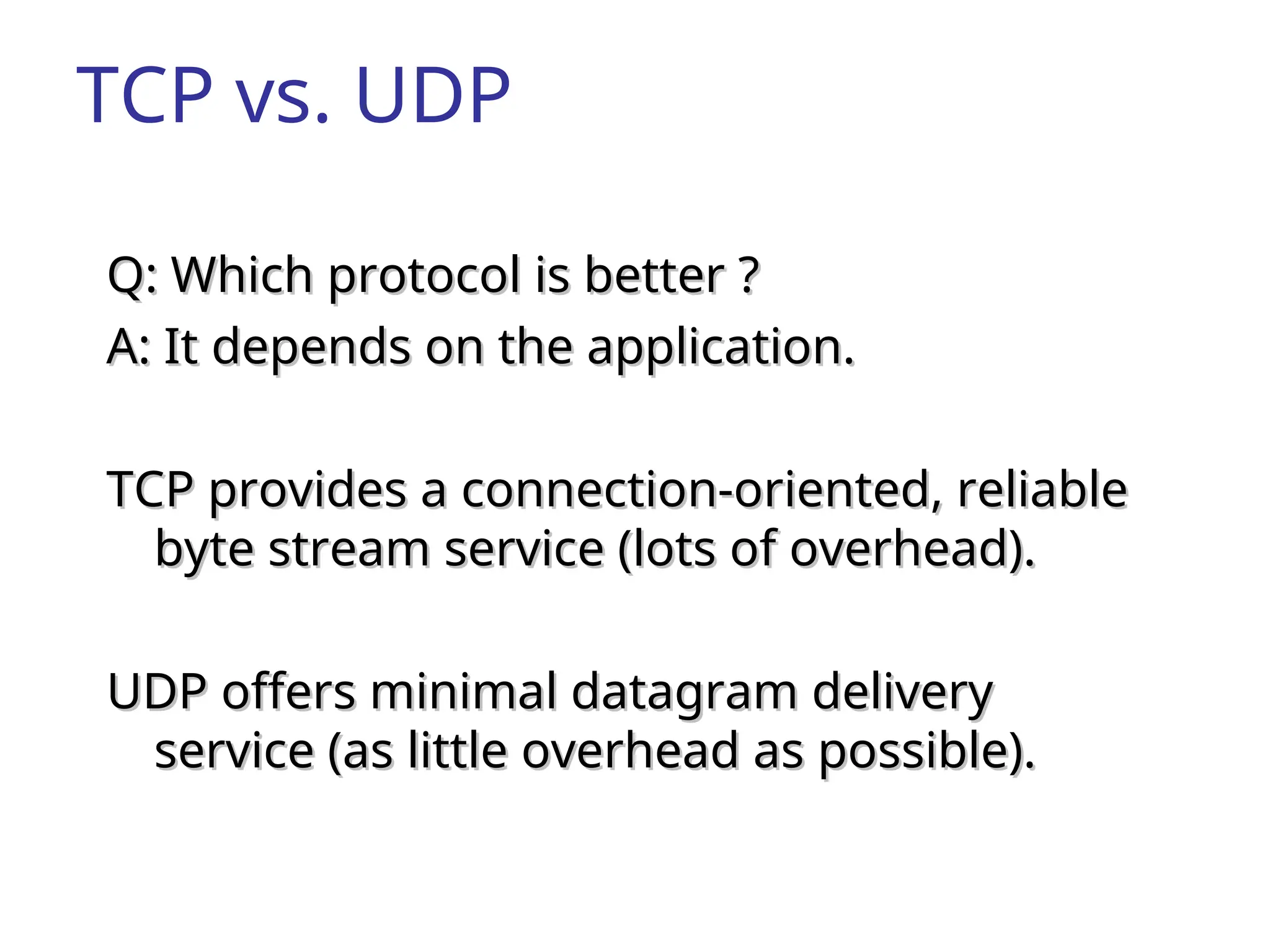
Q:Which protocol is better ?
Q: Which protocol is better ?
A: It depends on the application.
A: It depends on the application.
TCP provides a connection-oriented, reliable
TCP provides a connection-oriented, reliable
byte stream service (lots of overhead).
byte stream service (lots of overhead).
UDP offers minimal datagram delivery
UDP offers minimal datagram delivery
service (as little overhead as possible).
service (as little overhead as possible).
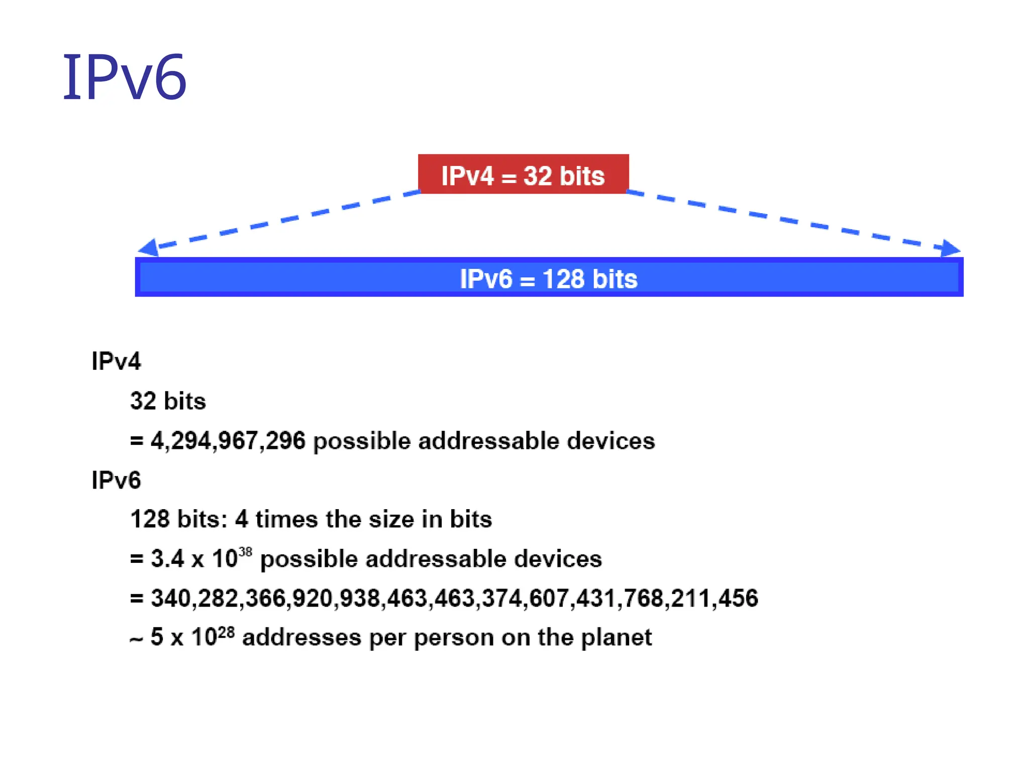
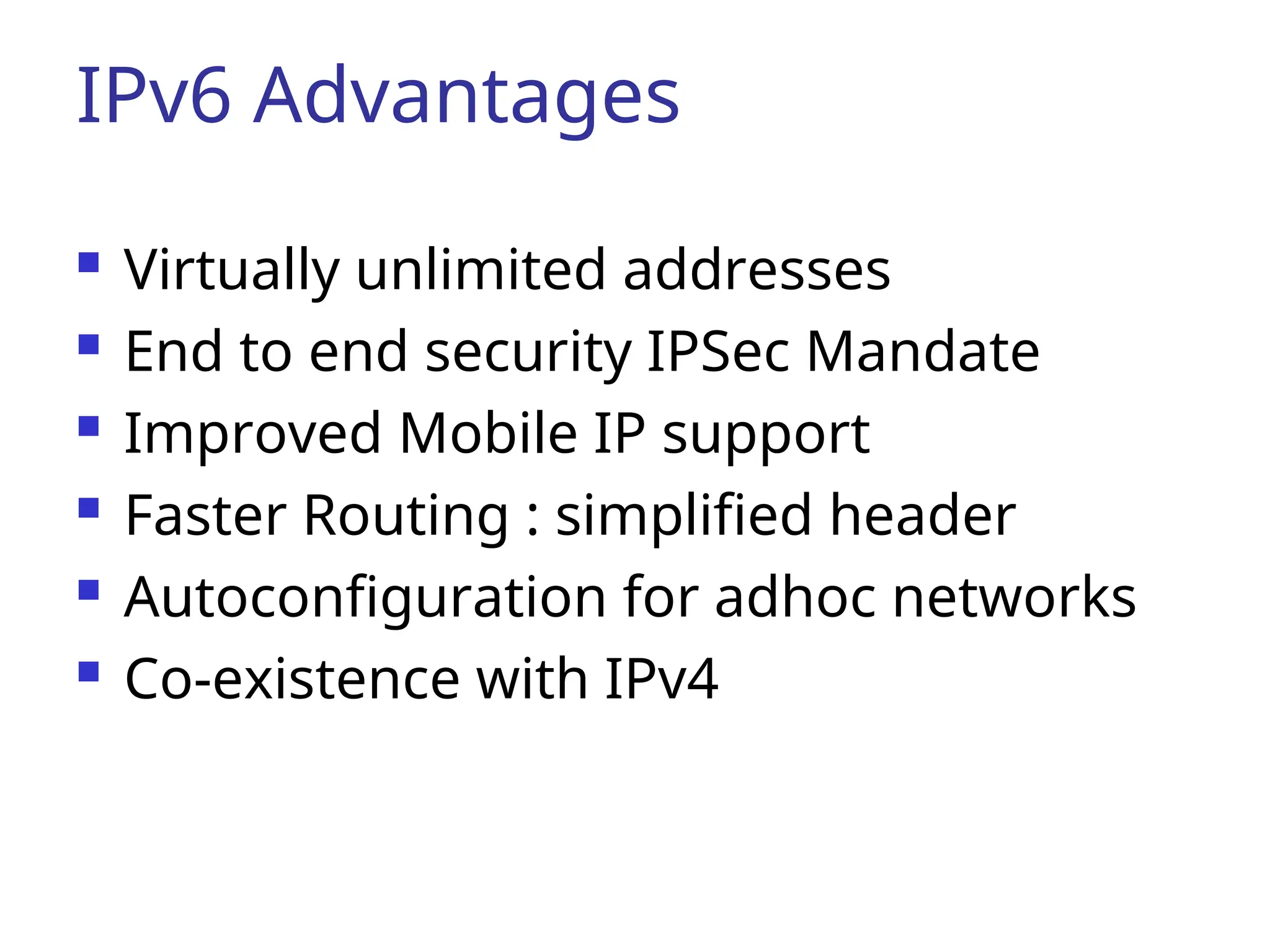
IPv6 Advantages
Virtuallyunlimited addresses
End to end security IPSec Mandate
Improved Mobile IP support
Faster Routing : simplified header
Autoconfiguration for adhoc networks
Co-existence with IPv4
![Advantages & Disadvantages of
using Repeaters
Advantages
Repeaters can extend a network’s total distance.
Repeaters do not seriously impact network performance
Certain repeaters can connect network using different
physical media.([ex. fiber optic, UTF, coaxial cable] is
possible.
Disadvantages
Can not connect different network architecture
Do not reduce network traffic.](https://image.slidesharecdn.com/chapter7-250706165506-f1d3828b/75/chapter7-ppt-introduction-to-networking-and-subneting-for-ip-version-four-17-2048.jpg)