Visit ebookmass.com todownload the full version and
explore more ebook or textbook
Essential C# 12.0, 8th Edition Mark Michaelis
_____ Click the link below to download _____
https://ebookmass.com/product/essential-c-12-0-8th-edition-
mark-michaelis/
Explore and download more ebook or textbook at ebookmass.com
2.
Here are somerecommended products that we believe you will be
interested in. You can click the link to download.
Beginning C++23 7th Edition Ivor Horton
https://ebookmass.com/product/beginning-c23-7th-edition-ivor-horton-2/
Beginning C++23 7th Edition Ivor Horton
https://ebookmass.com/product/beginning-c23-7th-edition-ivor-horton/
The Essential Cosmic Perspective (8th Edition ) 8th
Edition
https://ebookmass.com/product/the-essential-cosmic-perspective-8th-
edition-8th-edition/
Essential Orthopaedics 2nd Edition Mark D. Miller
https://ebookmass.com/product/essential-orthopaedics-2nd-edition-mark-
d-miller/
3.
Essential Reproduction (Essentials)8th Edition, (Ebook
PDF)
https://ebookmass.com/product/essential-reproduction-essentials-8th-
edition-ebook-pdf/
Essential Entomology 2nd Edition George C. Mcgavin
https://ebookmass.com/product/essential-entomology-2nd-edition-george-
c-mcgavin/
Essential Cosmic Perspective, The 8th Edition, (Ebook PDF)
https://ebookmass.com/product/essential-cosmic-perspective-the-8th-
edition-ebook-pdf/
eTextbook 978-0134446431 The Essential Cosmic Perspective
(8th Edition)
https://ebookmass.com/product/etextbook-978-0134446431-the-essential-
cosmic-perspective-8th-edition/
Modern C++ for Absolute Beginners: A Friendly Introduction
to the C++ Programming Language and C++11 to C++23
Standards, 2nd Edition Slobodan Dmitrovi■
https://ebookmass.com/product/modern-c-for-absolute-beginners-a-
friendly-introduction-to-the-c-programming-language-
and-c11-to-c23-standards-2nd-edition-slobodan-dmitrovic/
To my family:Elisabeth, Benjamin, Hanna, and Abigail. You
have sacrificed a husband and daddy for countless hours of
writing, frequently at times when he was needed most.
Thanks!
Also, to my friends and colleagues at IntelliTect. Thanks for
filling in for me when I was writing rather than doing my job
and for helping with the myriad of details to improve the
content and keep a code base like this running smoothly.
Thanks especially for making the EssentialCSharp.com
website a reality.
9.
Pearson’s Commitment toDiversity, Equity, and Inclusion
Pearson is dedicated to creating bias-free content that reflects the diversity of all
learners. We embrace the many dimensions of diversity, including but not limited to
race, ethnicity, gender, socioeconomic status, ability, age, sexual orientation, and
religious or political beliefs.
Education is a powerful force for equity and change in our world. It has the
potential to deliver opportunities that improve lives and enable economic mobility.
As we work with authors to create content for every product and service, we
acknowledge our responsibility to demonstrate inclusivity and incorporate diverse
scholarship so that everyone can achieve their potential through learning. As the
world’s leading learning company, we have a duty to help drive change and live up to
our purpose to help more people create a better life for themselves and to create a
better world.
Our ambition is to purposefully contribute to a world where:
While we work hard to present unbiased content, we want to hear from you about
any concerns or needs with this Pearson product so that we can investigate and
address them.
• Everyone has an equitable and lifelong opportunity to succeed through
learning.
• Our educational products and services are inclusive and represent the rich
diversity of learners.
• Our educational content accurately reflects the histories and experiences of the
learners we serve.
• Our educational content prompts deeper discussions with learners and
motivates them to expand their own learning (and worldview).
• Please contact us with concerns about any potential bias at https://
www.pearson.com/report-bias.html.
10.
Contents at aGlance
Contents vii
Foreword xv
Preface xvii
Acknowledgments xxxi
About the Author xxxiii
1 Introducing C# 1
2 Data Types 49
3 More with Data Types 93
4 Operators and Control Flow 137
5 Parameters and Methods 217
6 Classes 293
7 Inheritance 385
8 Interfaces 443
9 Introducing Structs and Records 487
10 Well-Formed Types 547
11 Exception Handling 601
12 Generics 623
13 Delegates and Lambda Expressions 683
14 Events 727
15 Collection Interfaces with Standard Query Operators 755
16 LINQ with Query Expressions 809
17 Building Custom Collections 833
v
11.
vi Contents ata Glance
18 Reflection, Attributes, and Dynamic Programming 881
19 Introducing Multithreading 933
20 Programming the Task-Based Asynchronous Pattern 975
21 Iterating in Parallel 1021
22 Thread Synchronization 1041
23 Platform Interoperability and Unsafe Code 1077
24 The Common Language Infrastructure 1107
Index 1131
Index of 8.0 Topics 1187
Index of 9.0 Topics 1190
Index of 10.0 Topics 1191
Index of 11.0 Topics 1192
Index of 12.0 Topics 1193
12.
Contents
Foreword xv
Preface xvii
Acknowledgmentsxxxi
About the Author xxxiii
1 Introducing C# 1
Hello, World 2
C# Syntax Fundamentals 12
Working with Variables 24
Console Input and Output 28
Managed Execution and the Common Language Infrastructure 38
Multiple .NET Frameworks 44
Summary 48
2 Data Types 49
Type Name Forms 50
Fundamental Numeric Types 52
More Fundamental Types 63
Conversions between Data Types 84
Summary 92
3 More with Data Types 93
Categories of Types 93
Declaring Types That Allow null 96
Implicitly Typed Local Variables 102
Tuples 103
Arrays 112
vii
13.
viii Contents
Summary 134
4Operators and Control Flow 137
Operators 137
Introducing Flow Control 156
Code Blocks ({}) 161
Code Blocks, Scopes, and Declaration Spaces 164
Boolean Expressions 166
Programming with null 173
Bitwise Operators (<<, >>, |, &, ^, ~) 181
Control Flow Statements, Continued 187
Jump Statements 200
C# Preprocessor Directives 206
Summary 215
5 Parameters and Methods 217
Calling a Method 218
Declaring a Method 225
Local Functions 232
Using Directives 233
Returns and Parameters on Main Method 242
Top-Level Statements 246
Advanced Method Parameters 247
Recursion 261
Method Overloading 264
Optional Parameters 267
Basic Error Handling with Exceptions 272
Summary 291
6 Classes 293
Declaring and Instantiating a Class 298
Instance Fields 302
Instance Methods 305
Using the this Keyword 306
Access Modifiers 314
Properties 316
14.
ix
Contents
Constructors 333
Non-Nullable ReferenceType Properties with Constructors 346
Nullable Attributes 354
Deconstructors 357
Static Members 359
Extension Methods 370
Encapsulating the Data 372
Nested Classes 376
Partial Classes 379
Summary 384
7 Inheritance 385
Derivation 386
Overriding the Base Class 397
Abstract Classes 410
All Classes Derive from System.Object 417
Type Checking 419
Pattern Matching 423
Avoid Pattern Matching When Polymorphism Is Possible 438
Summary 440
8 Interfaces 443
Introducing Interfaces 444
Polymorphism through Interfaces 446
Interface Implementation 451
Converting between the Implementing Class and Its Interfaces 457
Interface Inheritance 458
Multiple Interface Inheritance 461
Extension Methods on Interfaces 461
Versioning 464
Extension Methods versus Default Interface Members 480
Interfaces Compared with Abstract Classes 482
Interfaces Compared with Attributes 484
Summary 484
9 Introducing Structs and Records 487
15.
Visit https://ebookmass.com todayto explore
a vast collection of ebooks across various
genres, available in popular formats like
PDF, EPUB, and MOBI, fully compatible with
all devices. Enjoy a seamless reading
experience and effortlessly download high-
quality materials in just a few simple steps.
Plus, don’t miss out on exciting offers that
let you access a wealth of knowledge at the
best prices!
16.
x Contents
Reference Equalityversus Value Equality 493
Structs 494
Record Classes 500
Record Class Inheritance 503
Records 504
Overriding object Members 513
Customizing Record Behavior 521
Boxing 523
Enums 532
Summary 544
10 Well-Formed Types 547
Operator Overloading 548
Referencing Other Assemblies 557
Encapsulation of Types 564
Defining Namespaces 567
XML Comments 571
Garbage Collection and Weak References 576
Resource Cleanup 580
Lazy Initialization 596
Summary 598
11 Exception Handling 601
Multiple Exception Types 601
Catching Exceptions 604
Rethrowing an Existing Exception 607
General Catch Block 609
Guidelines for Exception Handling 610
Defining Custom Exceptions 614
Rethrowing a Wrapped Exception 618
Summary 622
12 Generics 623
C# without Generics 624
Introducing Generic Types 630
Constraints 646
17.
xi
Contents
Generic Methods 663
Covarianceand Contravariance 669
Generic Internals 676
Summary 681
13 Delegates and Lambda Expressions 683
Introducing Delegates 684
Declaring Delegate Types 688
Lambda Expressions 698
Statement Lambdas 699
Expression Lambdas 702
Anonymous Methods 705
Delegates Do Not Have Structural Equality 707
Outer Variables 710
Static Anonymous Functions 712
Expression Trees 716
Summary 724
14 Events 727
Coding the Publish–Subscribe Pattern with Multicast Delegates 728
Understanding Events 743
Summary 753
15 Collection Interfaces with Standard Query Operators 755
Collection Initializers 756
What Makes a Class a Collection: IEnumerable 759
Standard Query Operators 766
Anonymous Types with LINQ 796
Summary 806
16 LINQ with Query Expressions 809
Introducing Query Expressions 810
Query Expressions Are Just Method Invocations 829
Summary 831
17 Building Custom Collections 833
More Collection Interfaces 834
Primary Collection Classes 837
18.
xii Contents
Providing anIndexer 859
Returning null or an Empty Collection 862
Iterators 863
Summary 879
18 Reflection, Attributes, and Dynamic Programming 881
Reflection 881
nameof Operator 894
Attributes 895
Programming with Dynamic Objects 920
Summary 931
19 Introducing Multithreading 933
Multithreading Basics 935
Asynchronous Tasks 943
Canceling a Task 965
Working with System.Threading 972
Summary 973
20 Programming the Task-Based Asynchronous Pattern 975
Synchronously Invoking a High-Latency Operation 975
Asynchronously Invoking a High-Latency Operation Using the TPL 979
The Task-Based Asynchronous Pattern with async and await 984
Introducing Asynchronous Return of ValueTask<T> 991
Asynchronous Streams 994
IAsyncDisposable and the await using Declaration and Statement 998
Using LINQ with IAsyncEnumerable 999
Returning void from an Asynchronous Method 1001
Asynchronous Lambdas and Local Functions 1006
Task Schedulers and the Synchronization Context 1013
async/await with the Windows UI 1015
Summary 1019
21 Iterating in Parallel 1021
Executing Loop Iterations in Parallel 1021
Running LINQ Queries in Parallel 1032
19.
xiii
Contents
Summary 1039
22 ThreadSynchronization 1041
Why Synchronization? 1042
Timers 1073
Summary 1076
23 Platform Interoperability and Unsafe Code 1077
Platform Invoke 1078
Pointers and Addresses 1093
Executing Unsafe Code via a Delegate 1104
Summary 1105
24 The Common Language Infrastructure 1107
Defining the Common Language Infrastructure 1107
CLI Implementations 1109
.NET Standard 1113
Base Class Library 1113
C# Compilation to Machine Code 1114
Runtime 1116
Assemblies, Manifests, and Modules 1121
Common Intermediate Language 1124
Common Type System 1125
Common Language Specification 1125
Metadata 1126
.NET Native and Ahead of Time Compilation 1127
Summary 1128
Index 1131
Index of 8.0 Topics 1187
Index of 9.0 Topics 1190
Index of 10.0 Topics 1191
Index of 11.0 Topics 1192
Index of 12.0 Topics 1193
Foreword
Welcome to oneof the most venerable and trusted franchises you could dream of in
the world of C# books—and probably far beyond! Mark Michaelis’s Essential C#
book has been a classic for years, but it was yet to see the light of day when I first got
to know Mark.
In 2005, when LINQ (Language Integrated Query) was disclosed, I had only just
joined Microsoft, and I got to tag along to the PDC conference for the big reveal.
Despite my almost total lack of contribution to the technology, I thoroughly enjoyed
the hype. The talks were overflowing, the printed leaflets were flying off the tables
like hotcakes: It was a big day for C# and .NET, and I was having a great time.
It was pretty quiet in the hands-on labs area, though, where people could try out
the technology preview themselves with nice scripted walkthroughs. That’s where I
ran into Mark. Needless to say, he wasn’t following the script. He was doing his own
experiments, combing through the docs, talking to other folks, busily pulling together
his own picture.
As a newcomer to the C# community, I may have met a lot of people for the first
time at that conference—people with whom I have since formed great relationships.
But to be honest, I don’t remember them—it’s all a blur. The only one I remember
is Mark. Here is why: When I asked him if he was liking the new stuff, he didn’t just
join the rave. He was totally level-headed: “I don’t know yet. I haven’t made up my
mind about it.” He wanted to absorb and understand the full package, and until then
he wasn’t going to let anyone tell him what to think.
So instead of the quick sugar rush of affirmation I might have expected, I got to
have a frank and wholesome conversation, the first of many over the years, about
details, consequences, and concerns with this new technology. And so it remains:
Mark is an incredibly valuable community member for us language designers to
have, because he is super smart, insists on understanding everything to the core, and
has phenomenal insight into how things affect real developers. But perhaps most of
all, he is forthright and never afraid to speak his mind. If something passes the Mark
Test, then we know we can start feeling pretty good about it!
xv
22.
xvi Foreword
These arethe same qualities that make Mark such a great writer. He goes right to
the essence and communicates with great integrity, no sugarcoating, and a keen eye
for practical value and real-world problems. Mark has a great gift of providing clarity
and elucidation, and no one will help you get C# 12.0 like he does.
Enjoy!
ㅤ
—Mads Torgersen
Principal Architect, Microsoft
23.
Preface
Throughout the historyof software engineering, the methodology used to write
computer programs has undergone several paradigm shifts, each building on the
foundation of the former by increasing code organization and decreasing complexity.
This book takes you through these same paradigm shifts.
The beginning chapters take you through sequential programming structure, in
which statements are executed in the order in which they are written. The problem
with this model is that complexity increases exponentially as the requirements
increase. To reduce this complexity, code blocks are moved into methods, creating a
structured programming model. This allows you to call the same code block from
multiple locations within a program, without duplicating code. Even with this
construct, however, programs quickly become unwieldy and require further
abstraction. Object-oriented programming, introduced in Chapter 6, was the
response. In subsequent chapters, you will learn about additional methodologies,
such as interface-based programming, LINQ (and the transformation it makes to the
collection API), and eventually rudimentary forms of declarative programming (in
Chapter 18) via attributes.
This book has three main functions.
xvii
• It provides comprehensive coverage of the C# language, going beyond a
tutorial and offering a foundation upon which you can begin effective software
development projects.
• For readers already familiar with C#, this book provides insight into some of
the more complex programming paradigms and provides in-depth coverage of
the features introduced in the latest version of the language, C# 12.0 and
.NET 8.
• It serves as a timeless reference even after you gain proficiency with the
language.
24.
xviii Preface
The keyto successfully learning C# is to start coding as soon as possible. Don’t
wait until you are an “expert” in theory; start writing software immediately. As a
believer in iterative development, I hope this book enables even a novice
programmer to begin writing basic C# code by the end of Chapter 2.
Many topics are not covered in this book. You won’t find coverage of topics such
as ASP.NET, Entity Framework, Maui, smart client development, distributed
programming, and so on. Although these topics are relevant to .NET, to do them
justice requires books of their own. Fortunately, Essential C# 12.0 focuses on C# and
the types within the Base Class Library. Reading this book will prepare you to focus
on and develop expertise in any of the more advanced areas, given a strong
foundation in the C# langauge.
Target Audience for This Book
My challenge with this book was to keep advanced developers awake while not
abandoning beginners by using words such as assembly, link, chain, thread, and
fusion, as though the topic was more appropriate for blacksmiths than for
programmers. This book’s primary audience is experienced developers looking to
add another language to their quiver. However, I have carefully assembled this book
to provide significant value to developers at all levels.
• Beginners: If you are new to programming, this book serves as a resource to
help transition you from an entry-level programmer to a C# developer who is
comfortable with any C# programming task that’s thrown your way. This book
not only teaches you syntax but also trains you in good programming practices
that will serve you throughout your programming career.
• Structured programmers: Just as it’s best to learn a foreign language through
immersion, learning a computer language is most effective when you begin
using it before you know all the intricacies. In this vein, the book begins with a
tutorial that will be comfortable for those familiar with structured
programming, and by the end of Chapter 5, developers in this category should
feel at home writing basic control flow programs. However, the key to
excellence for C# developers is not memorizing syntax. To transition from
simple programs to enterprise development, the C# developer must think
natively in terms of objects and their relationships. To this end, Chapter 6’s
25.
xix
Preface
Beginner Topics introduceclasses and object-oriented development. The role
of historically structured programming languages such as C, COBOL, and
FORTRAN is still significant but shrinking, so it behooves software engineers
to become familiar with object-oriented development. C# is an ideal language
for making this transition because it was designed with object-oriented
development as one of its core tenets.
• Object-based and object-oriented developers: C++, Java, Python, TypeScript,
and Visual Basic programmers fall into this category. Many of you are already
completely comfortable with semicolons and curly braces. A brief glance at the
code in Chapter 1 reveals that, at its core, C# is like other C- and C++-style
languages that you already know.
• C# professionals: For those already versed in C#, this book provides a
convenient reference for less frequently encountered syntax. Furthermore, it
provides insight into language details and subtleties that are seldom addressed.
Most important, it presents the guidelines and patterns for programming robust
and maintainable code. This book also aids in the task of teaching C# to others.
With the emergence of C# 3.0 through 12.0, some of the most prominent
enhancements are
1. String interpolation (see Chapter 2)
2. Implicitly typed variables (see Chapter 3)
3. Tuples (see Chapter 3)
4. Nullable reference types (see Chapter 3)
5. Pattern matching (see Chapter 4)
6. Extension methods (see Chapter 6)
7. Partial methods (see Chapter 6)
8. Default interface members (see Chapter 8)
9. Anonymous types (see Chapter 12)
10.Generics (see Chapter 12)
26.
Visit https://ebookmass.com todayto explore
a vast collection of ebooks across various
genres, available in popular formats like
PDF, EPUB, and MOBI, fully compatible with
all devices. Enjoy a seamless reading
experience and effortlessly download high-
quality materials in just a few simple steps.
Plus, don’t miss out on exciting offers that
let you access a wealth of knowledge at the
best prices!
The details ofthe escapement may be seen in Fig. 96, which gives a
general view of a portion of the back plate of the clock movement,
supposing the pendulum removed; a and b are the front and back
plates respectively of the clock train; c is a cock supporting one end
of the crutch axis; d is the crutch rod carrying the pallets, and e an
arm carried by the crutch axis and fixed at f to the left-hand pallet
arm; g is a cock supporting a detent projecting towards the left and
curved at its extreme end; at a point near the top of the escape
wheel this detent carries a pin (jewel) for locking the wheel, and at
its extreme end there is a very light “passing spring.” The action of
the escapement is as follows:—Suppose the pendulum to be
swinging from the right hand. It swings quite freely until a pin at the
end of the arm e lifts the detent; the wheel escapes from the jewel
before mentioned, and the tooth next above the left-hand pallet
drops on the face of the pallet (the state shown in the figure), and
gives impulse to the pendulum; the wheel is immediately locked
again by the jewel, and the pendulum, now detached, passes on to
the left; in returning to the right, the light passing spring, before
spoken of, allows the pendulum to pass without disturbing the
detent; on going again to the left, the pendulum again receives
impulse as already described. The right-hand pallet forms no
essential part of the escapement, but is simply a safety pallet,
designed to catch the wheel in case of accident to the locking-stone
during the time that the left-hand pallet is beyond the range of the
wheel. The escape wheel carrying the seconds hand thus moves
once only in each complete or double vibration of the pendulum, or
every two seconds.
IV. The Chronometer.
We have now given a description of the astronomical clock—the
modern astronomical instrument which it was our duty to consider.
There is another time-keeper—the chronometer—which we have to
dwell upon. In the chronometer, instead of using the pendulum, we
29.
have a balance,the vibration of which is governed by a spiral spring,
instead of by gravity, as the pendulum is. By such means we keep
almost as accurate time as we do by employing a pendulum, the
balance being corrected for temperature on principles, one of which
we shall describe.
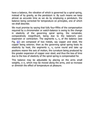
We must premise by saying that fully four-fifths of the compensation
required by a chronometer or watch-balance is owing to the change
in elasticity of the governing spiral spring, the remainder,
comparatively insignificant, being due to the balance’s own
expansion or contraction. The segments R1, R2 of the balance (see
Fig. 97) are composed of two metals, say copper and steel, the
copper being exterior; then as the governing spiral spring loses its
elasticity by heat, the segments R1, R2 curve round and take up
positions nearer the axis of motion, the curvature being produced by
the greater expansion of copper over steel; and thus the loss of time
due to the loss of elasticity of the spiral spring is compensated for.
This balance may be adjustable by placing on the arms small
weights, W W, which may be moved along the arms, and so increase
or diminish the effect of temperature at pleasure.
30.
Fig. 97.—Compensating Balance.
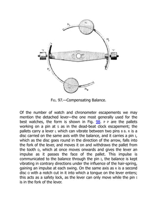
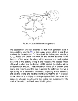
Ofthe number of watch and chronometer escapements we may
mention the detached lever—the one most generally used for the
best watches, the form is shown in Fig. 98. P P are the pallets
working on a pin at S as in the dead-beat clock escapement; the
pallets carry a lever L which can vibrate between two pins B B. R is a
disc carried on the same axis with the balance, and it carries a pin I,
which as the disc goes round in the direction of the arrow, falls into
the fork of the lever, and moves it on and withdraws the pallet from
the tooth D, which at once moves onwards and gives the lever an
impulse as it passes the face of the pallet. This impulse is
communicated to the balance through the pin I, the balance is kept
vibrating in contrary directions under the influence of the hair-spring,
gaining an impulse at each swing. On the same axis as R is a second
disc O with a notch cut in it into which a tongue on the lever enters;
this acts as a safety lock, as the lever can only move while the pin I
is in the fork of the lever.
31.
Fig. 98.—Detached LeverEscapement.
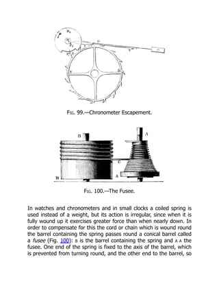
The escapement we next describe is that most generally used in
chronometers. S S, Fig. 99, is the escape wheel which is kept from
revolving by the detent D. On the axis of the balance are two discs,
R1, R2, placed one under the other. As the balance revolves in the
direction of the arrow, the pin P2 will come round and catch against
the point of the detent, lifting it and releasing the escape-wheel,
which will revolve, and the tooth T will hit against the stud P1, giving
the balance an impulse. The balance then swings on to the end of its
course and returns, and the stud P2 passes the detent as follows: a
light spring Y Y is fastened to the detent, projecting a little beyond it,
and it is this spring, and not the detent itself, that the pin P2 touches:
on the return of P2 it simply lifts the spring away from the detent and
passes it, whereas in advancing the spring was supported by the
point of the detent, and both were lifted together.
32.
Fig. 99.—Chronometer Escapement.
Fig.100.—The Fusee.
In watches and chronometers and in small clocks a coiled spring is
used instead of a weight, but its action is irregular, since when it is
fully wound up it exercises greater force than when nearly down. In
order to compensate for this the cord or chain which is wound round
the barrel containing the spring passes round a conical barrel called
a fusee (Fig. 100): B is the barrel containing the spring and A A the
fusee. One end of the spring is fixed to the axis of the barrel, which
is prevented from turning round, and the other end to the barrel, so
33.
that on windingup the clock by turning the fusee the cord becomes
coiled on the latter, and the more the spring is wound the nearer the
cord approaches the small end of the fusee, and has therefore less
power over it; while as the clock goes and the spring becomes
unwound, its power over the axis becomes greater. The power,
therefore, acting to turn the fusee remains pretty constant.
9. By Messrs. E. Dent and Co. of the Strand.
34.
CHAPTER XIV.
CIRCLE READING.
Oneof the great advantages which astronomy has received from the
invention of the telescope is the improved method of measuring
space and determining positions by the use of the telescope in the
place of pointers on the old instruments. The addition of modern
appliances to the telescope to enable it to be used as an accurate
pointer, has played a conspicuous part in the accurate measurement
of space, and the results are of such importance, and they have
increased so absolutely pari passu with the telescope, that we must
now say something of the means by which they have been brought
about.
For astronomy of position, in other words for the measurement of
space, we want to point the telescope accurately at an object. That
is to say, in the first instance we want circles, and then we want the
power of not only making perfect circles, but of reading them with
perfect accuracy; and where the arc is so small that the circle,
however finely divided, would help us but little, we want some
means of measuring small arcs in the eyepiece of the telescope
itself, where the object appears to us, as it is called, in the field of
view; we want to measure and inspect that object in the field of
view of the telescope, independently of circles or anything
extraneous to the field. We shall then have circles and micrometers
to deal with divisions of space, and clocks and chronographs to deal
with divisions of time.
We require to have in the telescope something, say two wires
crossed, placed in the field of view—in the round disc of light we see
in a telescope owing to the construction of the diaphragm—so as to
35.
be seen togetherwith any object. In the chapter on eyepieces it was
shown that we get at the focus the image of the object; and as that
is also the focus of the eyepiece, it is obvious that not only the
image in the air, as it were, but anything material we like to put in
that focus, is equally visible. By the simple contrivance of inserting in
this common focus two or more wires crossed and carried on a small
circular frame, we can mark any part of the field, and are enabled to
direct the telescope to any object.
In the Huyghenian eyepiece, Fig. 60, the cross should be between
the two convex lenses, for if we have an eyepiece of this kind the
focus will be at F, and so here we must have our cross wires; but, if
instead of this eyepiece we have one of the kind called Ramsden’s
eyepiece, Fig. 62, with the two convex surfaces placed inwards, then
the focus will be outside, at F, and nearer to the object-glass:
therefore we shall be able to change these eyepieces without
interfering with the system of wires in the focus of the telescope. We
hence see at once that the introduction of this contrivance, which is
due to Mr. Gascoigne, at once enormously increases the possibility of
making accurate observations by means of the telescope.
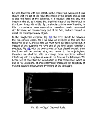
Fig. 101.—Diggs’ Diagonal Scale.
36.
Hipparchus was contentto ascertain the position of the celestial
bodies to within a third of a degree, and we are informed that Tycho
Brahe, by a diagonal scale, was able to bring it down to something
like ten seconds. Fig. 101 will show what is meant by this. Suppose
this to be part of the arc of Tycho’s circle, having on it the different
divisions and degrees. Now it is clear that when the bar which
carried the pointer swept over this arc, divided simply into degrees,
it would require a considerable amount of skill in estimating to get
very close to the truth, unless some other method were introduced;
and the method suggested by Diggs, and adopted by Tycho, was to
have a series of diagonal lines for the divisions of degrees; and it is
clear that the height of the diagonal line measured from the edge of
the circle could give, as it were, a longer base than the direct
distance between each division for determining the subdivisions of
the degree, and a slight motion of the pointer would make a great
difference in the point where it cuts the diagonal line. For instance, it
would not be easy to say exactly the fraction of division on the inner
circle at which the pointer in Fig. 101 rests, but it is evident that the
leading edge of the pointer cuts the diagonal line at three-fourths of
its length, as shown by the third circle; so the reading in this case is
seven and three-quarters; but that is, after all, a very rough method,
although it was all the astronomer had to depend upon in some
important observations.
37.
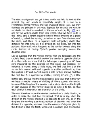
Fig. 102.—The Vernier.
Thenext arrangement we get is one which has held its own to the
present day, and which is beautifully simple. It is due to a
Frenchman named Vernier, and was invented about 1631. We may
illustrate the principle in this way. Suppose for instance we want to
subdivide the divisions marked on the arc of a circle, Fig. 102 a b,
and say we wish to divide them into tenths, what we have to do is
this—First, take a length equal to nine of these divisions on a piece
of metal, c, called the vernier, carried on an arm from the centre of
the circle, and then, on a separate scale altogether, divide that
distance not into nine, as it is divided on the circle, but into ten
portions. Now mark what happens as the vernier sweeps along the
circle, instead of having Tycho’s pointer sweeping across the
diagonal scale.
Let us suppose that the vernier moves with the telescope and the
circle is fixed; then when division 0 of the vernier is opposite division
6 on the circle we know that the telescope is pointing at 6° from
zero measured by the degrees on this scale; but suppose, for
instance, it moves along a little more, we find that line 1 of the
vernier is in contact with and opposite to another on the circle, then
the reading is 6° and ⅒°; it moves a little further, and we find that
the next line 2, is opposite to another, reading 6° and 2
10
°, a little
further still, and we find the next opposite. It is clear that in this way
we have a readier means of dividing all those spaces into tenths,
because if the length of the vernier is nine circle divisions the length
of each division on the vernier must be as nine is to ten, so that
each division is one-tenth less than that on the circle.
We must therefore move the vernier one-tenth of a circle division, in
order to make the next line correspond. That is to say, when the
division of the vernier marked 0 is opposite to any line, as in the
diagram, the reading is an exact number of degrees; and when the
division 1 is opposite, we have then the number of degrees given by
the division 0 plus one-tenth; when 2 is in contact, plus two-tenths;
38.
when 3 isin contact, plus three-tenths; when 4 is in contact, plus
four-tenths, and so on, till we get a perfect contact all through by
the 0 of the vernier coming to the next division on the circle, and
then we get the next degree. It is obvious that we may take any
other fraction than to for the vernier to read to, say 1
60
, then we take
a length of 59 circle divisions on the vernier and divide it into 60, so
that each vernier division is less than a circle division by 1
60
. This is a
method which holds its own on most instruments, and is a most
useful arrangement.
But most of us know that the division of the vernier has been
objected to as coarse and imperfect; and Sharp, Graham, Bird,
Ramsden, Troughton, and others found that it is easy to graduate a
circle of four or five feet in diameter, or more, so accurately and
minutely that five minutes of arc shall be absolutely represented on
every part of the circle. We can take a small microscope and place in
its field of view two cross wires, something like those we have
already mentioned, so as to be seen together with the divisions on
the circle, and then, by means of a screw with a divided head, we
can move the cross wires from division to division, and so, by noting
the number of turns of the screw required to bring the cross wires
from a certain fixed position, corresponding to the pointer in the
older instruments, to the nearest division, we can measure the
distance of that division from the fixed point or pointer, as it were,
just as well as if the circle itself were much more closely divided. We
can have matters so arranged that we may have to make, if we like,
ten turns of the screw in order to move the cross wires from one
graduation to the next, and we may have the milled head of the
screw itself divided into 100 divisions, so that we shall be able to
divide each of the ten turns into 100, or the whole division into
1,000 parts. It is then simply a question of dividing a portion of arc
equal to five minutes into a thousand, or, if one likes, ten thousand
parts by a delicate screw motion.
We are now speaking of instruments of precision, in which large
telescopes are not so necessary as large circles. With reference to
39.
instruments for physicaland other observations, large circles are not
so necessary as large telescopes, as absolute positions can be
determined by instruments of precision, and small arcs can, as we
shall see in the next chapter, be determined by a micrometer in the
eyepiece of the telescope.
40.
CHAPTER XV.
THE MICROMETER.
Itwill have been gathered from the previous chapter that the perfect
circles nowadays turned out by our best opticians, and armed in
different parts by powerful reading microscopes, in conjunction with
a cross wire in the field of view of the telescope to determine the
exact axis of collimation, enable large arcs to be measured with an
accuracy comparable to that with which an astronomical clock
enables us to measure an interval of time.
We have next to see by what method small arcs are measured in the
field of view of the telescope itself. This is accomplished by what are
termed micrometers, which are of various forms. Thus we have the
wire micrometer, the heliometer, the double-image micrometer, and
so on. These we shall now consider in succession, entering into
further details of their use, and the arrangements they necessitate
when we come to consider the instrument in conjunction with which
they are generally employed.
The history of the micrometer is a very curious one. We have already
spoken of a pair of cross wires replacing the pinnules of the old
astronomers in the field of view of the telescope, so that it might be
pointed to any celestial object very much more accurately than it
could be without such cross wires. This kind of micrometer was first
applied to a telescope by Gascoigne in 1639. In a letter to Crabtree
he writes:[10]
“If here (in the focus of the telescope) you place the
scale that measures ... or if here a hair be set that it appear
perfectly through the glass ... you may use it in a quadrant for the
finding of the altitude of the least star visible by the perspective
wherein it is. If the night be so dark that the hair or the pointers of
41.
the scale benot to be seen, I place a candle in a lanthorn, so as to
cast light sufficient into the glass, which I find very helpful when the
moon appeareth not, or it is not otherwise light enough.”
This then was the first “telescopic sight,” as these arrangements at
the common focus of the object-glass and eyepiece were at first
called. It is certain that we may date the micrometer from the
middle of the seventeenth century; but it is rather difficult to say
who it was who invented it. It is frequently attributed to a
Frenchman named Auzout, who is stated to have invented it in 1666;
but we have reason to know that Gascoigne had invented an
instrument for measuring small distances several years before.
Though first employed by Gascoigne, however, they were certainly
independently introduced on the Continent, and took various forms,
one of them being a reticule, or network of small silver threads,
suggested by the Marquis Malvasia, the arc interval of which was
determined by the aid of a clock. Huyghens had before this
proposed, as specially applicable to the measures of the diameters
of planets and the like, the introduction of a tapering slip of metal.
The part of the slip which exactly eclipsed the planet was noted; it
was next measured by a pair of compasses, and having the focal
length of the telescope, the apparent diameter was ascertained.
42.
Fig. 103.—System ofWires in a Transit
Eyepiece.
Malvasia’s suggestion was soon seized upon for determinations of
position. Römer introduced into the first transit instrument a
horizontal and a number of vertical wires. The interval between the
three he generally used was thirty-four seconds in the equator, and
the time was noted to half seconds. The field was illuminated by
means of a polished ring placed outside of the object-glass. The
simple system of cross wires, then, though it has done its work, is
not to be found in the telescope now, either to mark the axis of
collimation, or roughly to measure small distances. For the first
purpose a much more elaborate system than that introduced by
Römer is used. We have a large number of vertical wires, the
principal object of which is, in such telescopes as the transit, to
determine the absolute time of the passage of either a star or
planet, or the sun or moon, over the meridian; and one or more
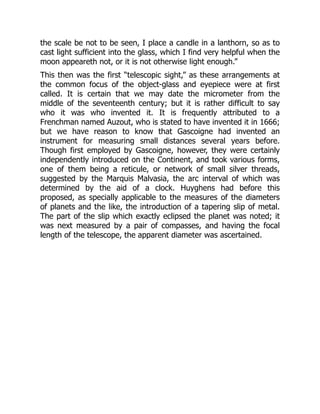
43.
horizontal ones. Theseconstitute the modern transit eyepiece, a
very simple form of which is shown in the above woodcut.
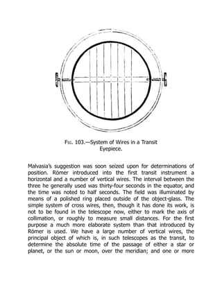
THE WIRE MICROMETER.
The wire micrometer is due to suggestions made independently by
Hooke and Auzout, who pointed out how valuable the reticule of
Malvasia would be if one of the wires were movable.
Fig. 104.—Wire Micrometer. x and y are thicker
wires for measuring positions on a separate
plate to be laid over the fine wires.
The first micrometer in which motion was provided consisted of two
plates of tin placed in the eyepiece, being so arranged and
connected by screws that the distances between the two edges of
the tin plates could be determined with considerable accuracy. A
planet could then be, as it were, grasped between the two plates,
and its diameter measured; it is very obvious that what would do as
well as these plates of tin would be two wires or hairs representing
the edges of these tin plates; and this soon after was carried out by
Hooke, who left his mark in a very decided way on very many
astronomical arrangements of that time. He suggested that all that
was necessary to determine the diameter of Saturn’s rings was to
have a fixed wire in the eyepiece, and a second wire travelling in the
field of view, so that the planet or the ring could be grasped
between those two wires.
44.
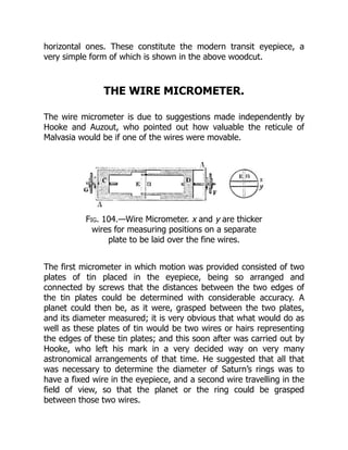
The wire-micrometer. Fig.104, differs little from the one Hooke and
Auzout suggested, A A is the frame, which carries two slides, C and D,
across the ends of each of which fine wires, E and B, are stretched;
then, by means of screws, F and G, threaded through these movable
slides and passing through the frame A A, the wires can be moved
near to, or away from, each other. Care must be taken that the
threads of the screw are accurate from one end to the other, so that
one turn of the screw when in one position would move the wire the
same distance as a turn when in another position. In this micrometer
both wires are movable, so as to get a wide separation if needful,
but in practice only one is so, the other remaining a fixture in the
middle of the field of view. There is a large head to the screw, which
is called the micrometer screw, marked into divisions, so that the
motion of the wire due to each turn of the screw may be divided,
say into 100 parts, by actual division against a fixed pointer, and
further into 1,000 parts by estimation of the parts of each division.
Hooke suggested that, if we had a screw with 100 turns to an inch,
and could divide these into 1,000 parts, we should obviously get the
means of dividing an inch into 100,000 parts; and so, if we had a
screw which would give 100 turns from one side of the field of view
of the telescope to the other, we should have an opportunity of
dividing the field of view of any telescope into something like
100,000 parts in any direction we chose.
The thick wires, x, y, are fixed to the plate in front of, but almost
touching, the fine wires, and in measuring, for instance, the distance
of two stars the whole instrument is turned round until these wires
are parallel to the direction of the imaginary line joining them.
This was the way in which Huyghens made many important
measures of the diameters of different objects and the distances of
different stars. Thus far we are enabled to find the number of
divisions on the micrometer screw that corresponds to the distance
from one star to another, or across a planet, but we want to know
the number of seconds of arc in the distance measured.
45.
In order todo this accurately we must determine how many
divisions of the screw correspond to the distance of the wires when
on two stars, say, one second apart. Here we must take advantage
of the rate at which a star travels across the field when the
telescope is fixed, and we separate the wires by a number of turns
of the screw, say twenty, and find what angle this corresponds to, by
letting a star on or near the equator[11]
traverse the field, and
noticing the time it requires to pass from one wire to the next.
Suppose it takes 26⅔ seconds, then, as fifteen seconds of arc pass
over in one second of time, we must multiply 26 by 15, which gives
400, so that the distance from wire to wire is 400 seconds of arc;
but this is due to twenty revolutions of the screw, so that each
revolution corresponds to 400
20
˝, or twenty seconds, and as each
revolution is divided into 100 parts, and 20
100
˝ = ⅕˝ therefore each
division corresponds to ⅕˝ of arc.
We shall return to the use of this most important instrument when
we have described the equatorial, of which it is the constant
companion.
THE HELIOMETER.
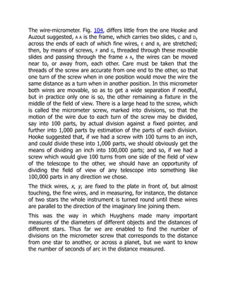
46.
Fig. 106.—Object-glass
cut intotwo parts.
Fig. 105.—A B C. Images of Jupiter supposed to
be touching; B being produced by duplication, C
duplicate image on the other side of A.
A B, Double Star; A, A´ & B, B´, the
appearance when duplicate image is moved to
the right; A´, A & B´, B, the same when moved
to the left.
There are other kinds of micrometers
which we must also briefly consider. In
the heliometer[12]
we get the power of
measuring distances by doubling the
images of the objects we see, by means
of dividing the object-glass. The two
circles, A and B, Fig. 105, represent the
two images of Jupiter formed, as we
shall show presently, and touching each
other; now, if by any means we can
make B travel over A till it has the
position C, also just touching A, it will
manifestly have travelled over a
distance equal to the diameters of A and
B, so that if we can measure the distance traversed and divide it by
2, we shall get the diameter of the circle A, or the planet. The same
principle applies to double stars, for if we double the stars A and B,
Fig. 105, so that the secondary images become A´ and B´, we can
move A´ over B, and then only three stars will be visible; we can then
move the secondary images back over A and B till B´ comes over A,
and the second image of A comes to A´. It is thus manifest that the
images A´ and B´ on being moved to A´ and B´ in the second position
have passed over double their distance apart. Now all double-image
micrometers depend on this principle, and first we will explain how
this duplication of images is made in the heliometer. It is clear that
we shall not alter the power of an object-glass to bring objects to
47.
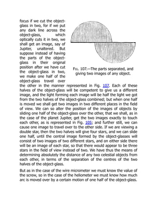
Fig. 107.—The partsseparated, and
giving two images of any object.
focus if we cut the object-
glass in two, for if we put
any dark line across the
object-glass, which
optically cuts it in two, we
shall get an image, say of
Jupiter, unaltered. But
suppose instead of having
the parts of the object-
glass in their original
position after we have cut
the object-glass in two,
we make one half of the
object-glass travel over
the other in the manner represented in Fig. 107. Each of these
halves of the object-glass will be competent to give us a different
image, and the light forming each image will be half the light we got
from the two halves of the object-glass combined; but when one half
is moved we shall get two images in two different places in the field
of view. We can so alter the position of the images of objects by
sliding one half of the object-glass over the other, that we shall, as in
the case of the planet Jupiter, get the two images exactly to touch
each other, as is represented in Fig. 105; and further still, we can
cause one image to travel over to the other side. If we are viewing a
double star, then the two halves will give four stars, and we can slide
one half, until the central image formed by the object-glasses will
consist of two images of two different stars, and on either side there
will be an image of each star, so that there would appear to be three
stars in the field of view instead of two. We have thus the means of
determining absolutely the distance of any two celestial objects from
each other, in terms of the separation of the centres of the two
halves of the object-glass.
But as in the case of the wire micrometer we must know the value of
the screw, so in the case of the heliometer we must know how much
arc is moved over by a certain motion of one half of the object-glass.
48.
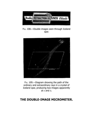
Fig. 108.—Double imagesseen through Iceland
spar.
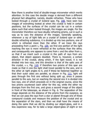
Fig. 109.—Diagram showing the path of the
ordinary and extraordinary rays in a crystal of
Iceland spar, producing two images apparently
at E and O.
THE DOUBLE-IMAGE MICROMETER.
49.
Now there isanother kind of double-image micrometer which merits
attention. In this case the double image is derived from a different
physical fact altogether, namely, double refraction. Those who have
looked through a crystal of Iceland spar, Fig. 108, have seen two
images of everything looked at when the crystal is held in certain
positions, but the surfaces of the crystal can be cut in a certain
plane such that when looked through, the images are single. For the
micrometer therefore we have doubly refracting prisms, cut in such a
way as to vary the distance of the images. Generally speaking,
whenever a ray of light falls on a crystal of Iceland spar or other
double refracting substance, it is divided up into two portions, one of
which is refracted more than the other. If we trace the rays
proceeding from a point S, Fig. 109, we find one portion of the light
reaching the eye is more refracted at the surfaces than the other,
and consequently one appears to come from E and the other from O,
so that if we insert such a crystal in the path of rays from any
object, that object appears doubled. There is, however, a certain
direction in the crystal, along which, if the light travel, it is not
divided into two rays, and this direction is that of the optic axis of
the crystal, A A, Fig. 110; if therefore two prisms of this spar are
made so that in one the light shall travel parallel to the axis, and in
the other at right angles to it, and if these be fastened together so
that their outer sides are parallel, as shown in Fig. 111, light will
pass through the first one without being split up, since it passes
parallel to the axis, but on reaching the second one it is divided into
two rays, one of which proceeds on in the original course, since the
two prisms counteract each other for this ray, while the other ray
diverges from the first one, and gives a second image of the object
in front of the telescope, as shown in Fig. b. The separation of the
image depends on the distance of the prisms from the eyepiece, so
that we can pass the rays from a star or planet through one of these
compound crystals and measure the position of the crystal and so
the separation of the stars, and then we shall have the means of
doing the same that we did by dividing our object-glass, and in a
less expensive way, for to take a large object-glass of eight or ten
50.
inches in diameterand cut it in two is a brutal operation, and has
generally been repented of when it has been done.
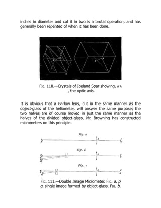
Fig. 110.—Crystals of Iceland Spar showing, A A
´, the optic axis.
It is obvious that a Barlow lens, cut in the same manner as the
object-glass of the heliometer, will answer the same purpose; the
two halves are of course moved in just the same manner as the
halves of the divided object-glass. Mr. Browning has constructed
micrometers on this principle.
Fig. 111.—Double Image Micrometer. Fig. a, p
q, single image formed by object-glass. Fig. b,
51.
p1 q1, p2q2, images separated by the double
refracting prism. Fig. c, same, separated less,
by the motion of the prism.
There is yet another double-image micrometer depending on the
power of a prism to alter the direction of rays of light. It is
constructed by making two very weak prisms, i.e., having their sides
very nearly parallel, and cutting them to a circular shape; these are
mounted in a frame one over the other with power to turn one
round, so that in one position they both act in the same direction,
and in the opposite one they neutralise each other; these are carried
by radial arms, and are placed either in front of the object-glass or
at such a distance from it inside the telescope that they intercept
one half of the light, and the remaining portion goes to form the
usual image, while the other is altered in its course by the prism and
forms another image, and this alteration depends on the position of
the movable prism.
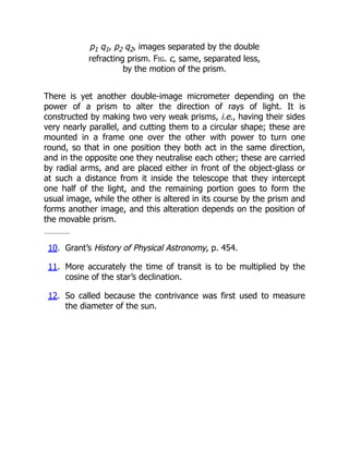
10. Grant’s History of Physical Astronomy, p. 454.
11. More accurately the time of transit is to be multiplied by the
cosine of the star’s declination.
12. So called because the contrivance was first used to measure
the diameter of the sun.
CHAPTER XVI.
THE TRANSITCIRCLE.
We are now, then, in full possession of the stock-in-trade of the
modern astronomer—the telescope, the clock, and the circle,—and
we have first to deal with what is termed astronomy of position, that
branch of the subject which enables us to determine the exact
position of the heavenly bodies in the celestial sphere at any instant
of time.
Before, however, we proceed with modern methods, it will be well,
on the principle of reculer pour mieux sauter, to refer back to the old
ones in order that we can the better see how the modern
instruments are arranged for doing the work which Tycho, for
instance, had to do, and which he accomplished by means of the
instruments of which we have already spoken.
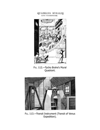
First of all let us refer to the Mural Quadrant, in which we have the
germ of a great deal of modern work, its direct descendant being
the Transit Circle of the present time.
We begin then by referring to the hole in the wall at which Tycho is
pointing (see Fig. 112), and the circle, of which the hole was the
centre, opposite to it, on which the position of the body was
observed, and its declination and right ascension determined. This
then was Tycho’s arrangement for determining the two co-ordinates,
right ascension and declination, measured from the meridian and
equator. It is to be hoped that the meaning of right ascension and
declination is already clear to our readers, because these terms refer
to the fundamental planes, and distances as measured from them
are the very A B C of anything that one has to say about
astronomical instruments.
54.
We know thatTycho had two things to do. In the first place he had
to note when a star was seen through the slit in the wall, which was
Tycho’s arrangement for determining the southing of a star, the sun,
or the moon; and then to give the instant when the object crossed
the sight to the other observer, who noted the time by the clocks.
Secondly, he had to note at which particular portion of the arc the
sight had to be placed, and so the altitude or the zenith distance of
the star was determined; and then, knowing the latitude of the
place, he got the two co-ordinates, the right ascension and
declination.
How does the modern astronomer do this? Here is an instrument
which, without the circle to tell the altitude at the same time, will
give some idea of the way in which the modern astronomer has to
go to work. In this we have what is called the Transit Instrument,
Fig. 113; it is simply used for determining the transit of stars over
the meridian. It consists essentially of a telescope mounted on
trunnions, like a cannon, having in the eyepiece, not simple cross
wires, but a system of wires, to which reference has already been
made, so that the mean of as many observations as there are wires
can be taken; and in this way Tycho’s hole in the wall is completely
superseded. The quadrant is represented by a circle on the
instrument called the transit circle, of which for the present we defer
consideration.
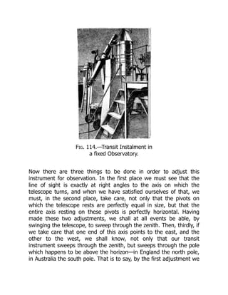
Fig. 114.—Transit Instalmentin
a fixed Observatory.
Now there are three things to be done in order to adjust this
instrument for observation. In the first place we must see that the
line of sight is exactly at right angles to the axis on which the
telescope turns, and when we have satisfied ourselves of that, we
must, in the second place, take care, not only that the pivots on
which the telescope rests are perfectly equal in size, but that the
entire axis resting on these pivots is perfectly horizontal. Having
made these two adjustments, we shall at all events be able, by
swinging the telescope, to sweep through the zenith. Then, thirdly, if
we take care that one end of this axis points to the east, and the
other to the west, we shall know, not only that our transit
instrument sweeps through the zenith, but sweeps through the pole
which happens to be above the horizon—in England the north pole,
in Australia the south pole. That is to say, by the first adjustment we
57.
shall be ableto describe a great circle; by the second, this circle will
pass through the zenith; and by the third, from the south of the
horizon to the north, through the pole. Of course, if the pole star
were at the pole, all we should have to do would be to adjust the
instrument (having determined the instrument to be otherwise
correct) so as simply to point to the pole star, and then we should
assure ourselves of the east and west positions of the axis. Some
details may here be of interest.
The first adjustment to be made is that the line of sight or
collimation shall be at right angles to the axis on which the
instrument moves: to find the error and correct it, bring the
telescope into a horizontal position and place a small object at a
distance away, in such a position that its image is bisected by the
central wire of the transit, then lift the instrument from its bearings
or Ys, as they are called, and reverse the pivots east for west, and
again observe the object. If it is still bisected, the adjustment is
correct, but if not, then half the angle between the new direction in
which the telescope points and the first one as marked by the object
is the collimation error, which may be ascertained by measuring the
distance from the object to the central wire, by a micrometer in the
field of view, and converting the distance into arc. To correct it, bring
the central wire half way up to the object by motion of the wire, and
complete the other half by moving the object itself, or by moving the
Ys of the instrument. This of course must be again repeated until the
adjustment is sensibly correct.
The second adjustment is to make the pivots horizontal. Place a
striding level on the pivots and bring the bubble to zero by the set
screws of the level, or note the position of it; then reverse the level
east for west, and then if the bubble remains at the same place the
axis of motion is horizontal, but, if not, raise or lower the movable Y
sufficiently to bring the bubble half way to its original position, and
complete the motion of the bubble, if necessary, by the level screw
until there is no alteration in the position of the bubble on reversing
the level.
58.
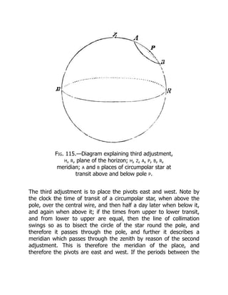
Fig. 115.—Diagram explainingthird adjustment,
H, R, plane of the horizon; H, Z, A, P, B, R,
meridian; A and B places of circumpolar star at
transit above and below pole P.
The third adjustment is to place the pivots east and west. Note by
the clock the time of transit of a circumpolar star, when above the
pole, over the central wire, and then half a day later when below it,
and again when above it; if the times from upper to lower transit,
and from lower to upper are equal, then the line of collimation
swings so as to bisect the circle of the star round the pole, and
therefore it passes through the pole, and further it describes a
meridian which passes through the zenith by reason of the second
adjustment. This is therefore the meridian of the place, and
therefore the pivots are east and west. If the periods between the
59.
Welcome to ourwebsite – the ideal destination for book lovers and
knowledge seekers. With a mission to inspire endlessly, we offer a
vast collection of books, ranging from classic literary works to
specialized publications, self-development books, and children's
literature. Each book is a new journey of discovery, expanding
knowledge and enriching the soul of the reade
Our website is not just a platform for buying books, but a bridge
connecting readers to the timeless values of culture and wisdom. With
an elegant, user-friendly interface and an intelligent search system,
we are committed to providing a quick and convenient shopping
experience. Additionally, our special promotions and home delivery
services ensure that you save time and fully enjoy the joy of reading.
Let us accompany you on the journey of exploring knowledge and
personal growth!
ebookmass.com


![CHAPTER XV.
THE MICROMETER.
It will have been gathered from the previous chapter that the perfect
circles nowadays turned out by our best opticians, and armed in
different parts by powerful reading microscopes, in conjunction with
a cross wire in the field of view of the telescope to determine the
exact axis of collimation, enable large arcs to be measured with an
accuracy comparable to that with which an astronomical clock
enables us to measure an interval of time.
We have next to see by what method small arcs are measured in the
field of view of the telescope itself. This is accomplished by what are
termed micrometers, which are of various forms. Thus we have the
wire micrometer, the heliometer, the double-image micrometer, and
so on. These we shall now consider in succession, entering into
further details of their use, and the arrangements they necessitate
when we come to consider the instrument in conjunction with which
they are generally employed.
The history of the micrometer is a very curious one. We have already
spoken of a pair of cross wires replacing the pinnules of the old
astronomers in the field of view of the telescope, so that it might be
pointed to any celestial object very much more accurately than it
could be without such cross wires. This kind of micrometer was first
applied to a telescope by Gascoigne in 1639. In a letter to Crabtree
he writes:[10]
“If here (in the focus of the telescope) you place the
scale that measures ... or if here a hair be set that it appear
perfectly through the glass ... you may use it in a quadrant for the
finding of the altitude of the least star visible by the perspective
wherein it is. If the night be so dark that the hair or the pointers of](https://image.slidesharecdn.com/21064-250305033900-e14a7909/85/Essential-C-12-0-8th-Edition-Mark-Michaelis-40-320.jpg)
![In order to do this accurately we must determine how many
divisions of the screw correspond to the distance of the wires when
on two stars, say, one second apart. Here we must take advantage
of the rate at which a star travels across the field when the
telescope is fixed, and we separate the wires by a number of turns
of the screw, say twenty, and find what angle this corresponds to, by
letting a star on or near the equator[11]
traverse the field, and
noticing the time it requires to pass from one wire to the next.
Suppose it takes 26⅔ seconds, then, as fifteen seconds of arc pass
over in one second of time, we must multiply 26 by 15, which gives
400, so that the distance from wire to wire is 400 seconds of arc;
but this is due to twenty revolutions of the screw, so that each
revolution corresponds to 400
20
˝, or twenty seconds, and as each
revolution is divided into 100 parts, and 20
100
˝ = ⅕˝ therefore each
division corresponds to ⅕˝ of arc.
We shall return to the use of this most important instrument when
we have described the equatorial, of which it is the constant
companion.
THE HELIOMETER.](https://image.slidesharecdn.com/21064-250305033900-e14a7909/85/Essential-C-12-0-8th-Edition-Mark-Michaelis-45-320.jpg)
![Fig. 106.—Object-glass
cut into two parts.
Fig. 105.—A B C. Images of Jupiter supposed to
be touching; B being produced by duplication, C
duplicate image on the other side of A.
A B, Double Star; A, A´ & B, B´, the
appearance when duplicate image is moved to
the right; A´, A & B´, B, the same when moved
to the left.
There are other kinds of micrometers
which we must also briefly consider. In
the heliometer[12]
we get the power of
measuring distances by doubling the
images of the objects we see, by means
of dividing the object-glass. The two
circles, A and B, Fig. 105, represent the
two images of Jupiter formed, as we
shall show presently, and touching each
other; now, if by any means we can
make B travel over A till it has the
position C, also just touching A, it will
manifestly have travelled over a
distance equal to the diameters of A and
B, so that if we can measure the distance traversed and divide it by
2, we shall get the diameter of the circle A, or the planet. The same
principle applies to double stars, for if we double the stars A and B,
Fig. 105, so that the secondary images become A´ and B´, we can
move A´ over B, and then only three stars will be visible; we can then
move the secondary images back over A and B till B´ comes over A,
and the second image of A comes to A´. It is thus manifest that the
images A´ and B´ on being moved to A´ and B´ in the second position
have passed over double their distance apart. Now all double-image
micrometers depend on this principle, and first we will explain how
this duplication of images is made in the heliometer. It is clear that
we shall not alter the power of an object-glass to bring objects to](https://image.slidesharecdn.com/21064-250305033900-e14a7909/85/Essential-C-12-0-8th-Edition-Mark-Michaelis-46-320.jpg)


![[Ebooks PDF] download C How to Program 1ST Edition Harvey M. Deitel full chap...](https://cdn.slidesharecdn.com/ss_thumbnails/50876-241223092440-32e628ff-thumbnail.jpg?width=640&height=640&fit=bounds)


![[Ebooks PDF] download C Package 100 Knock 1 Hour Mastery Series 2024 Edition ...](https://cdn.slidesharecdn.com/ss_thumbnails/77950-250115210538-3185d3d2-thumbnail.jpg?width=640&height=640&fit=bounds)


