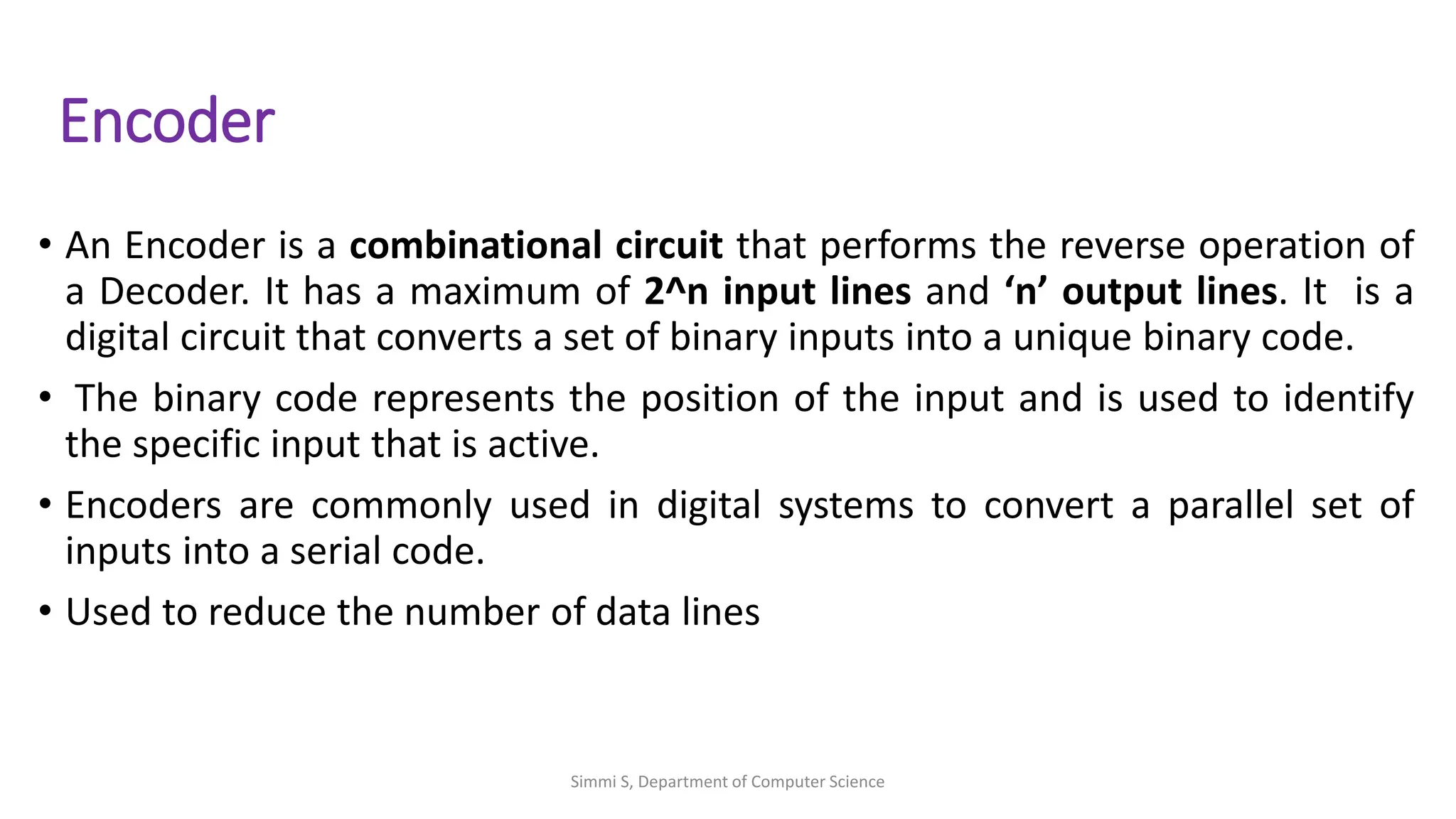
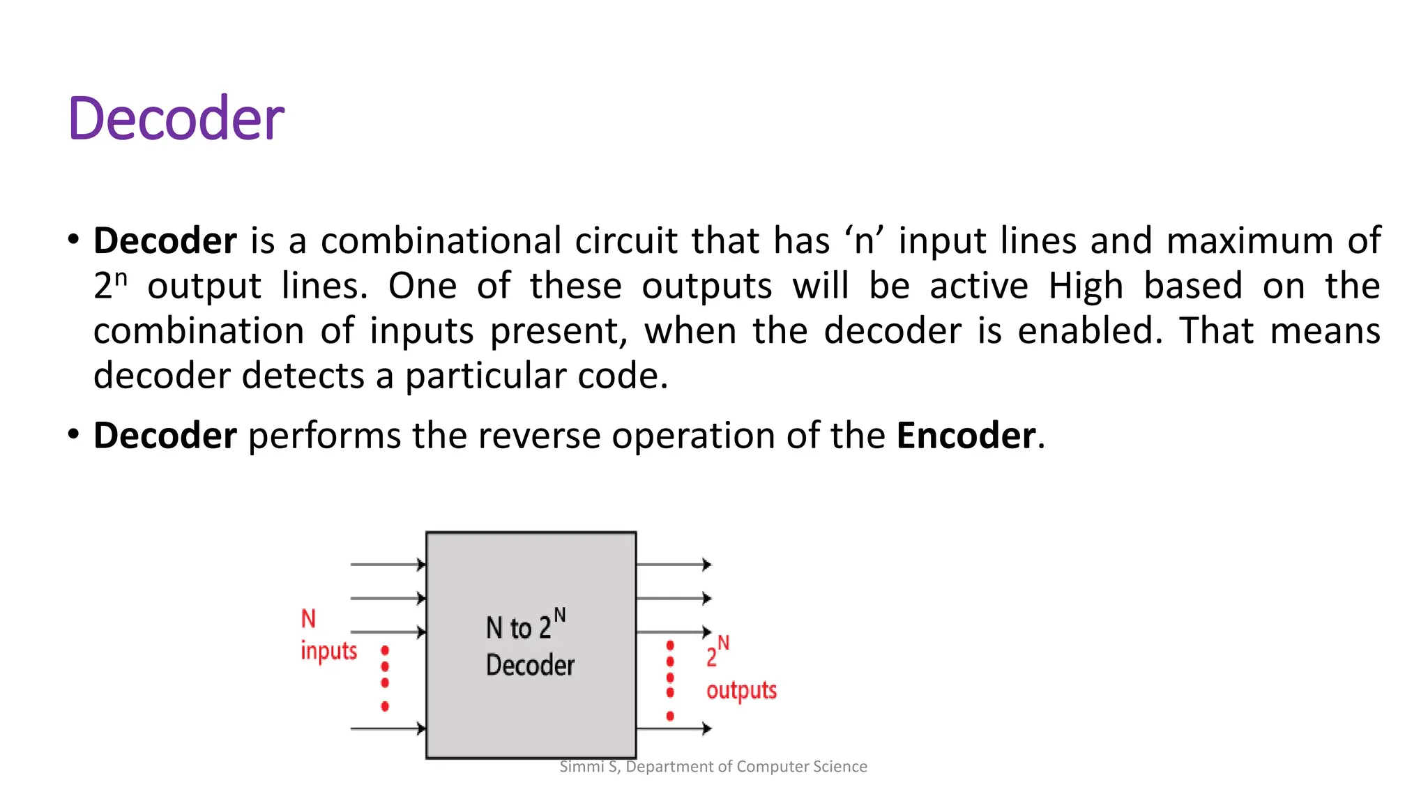
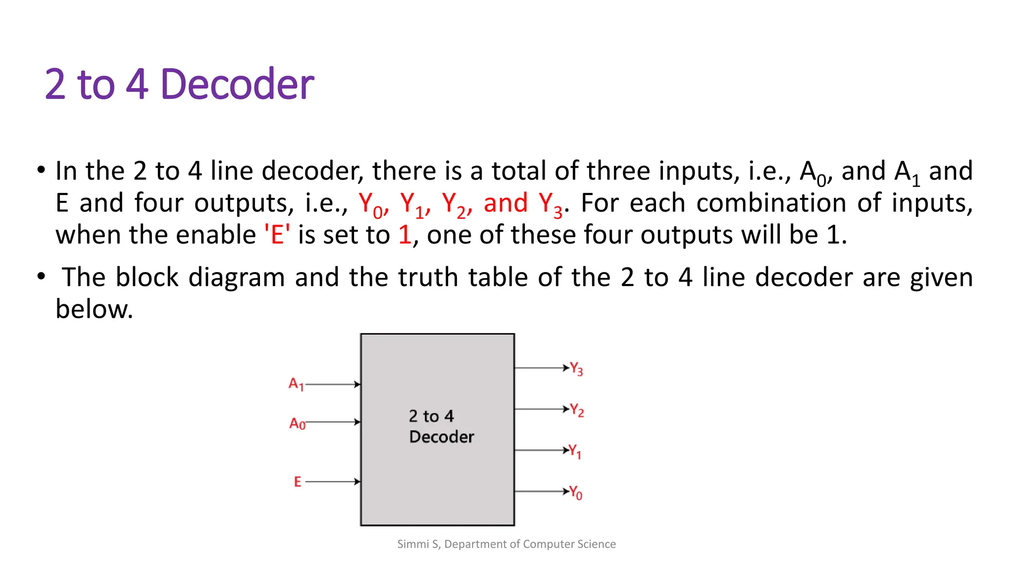
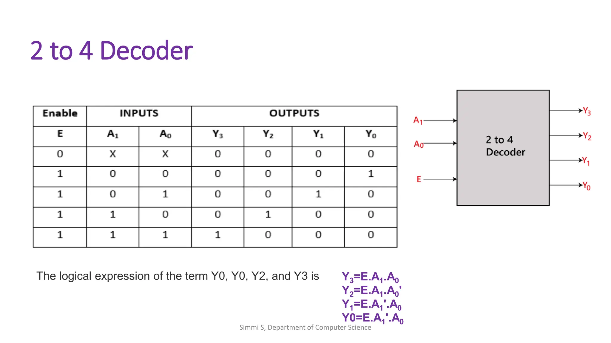
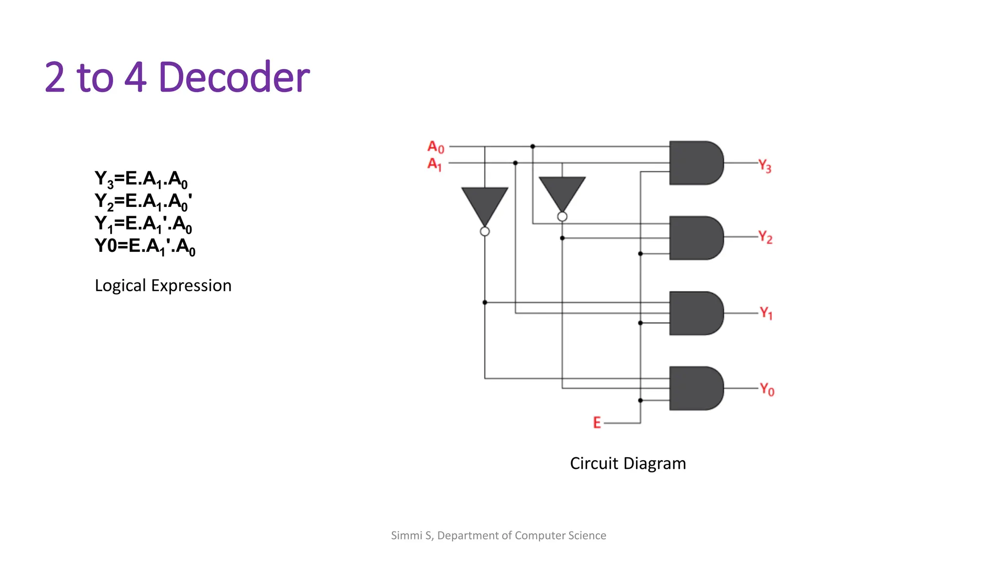
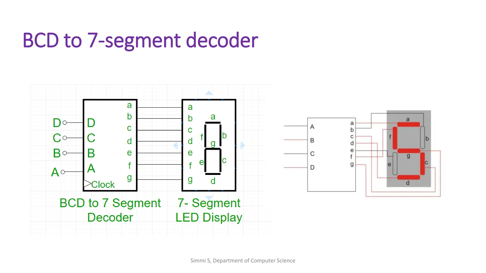
Encoder & Decoder
21BCA2T312:Digital Electronics
SIMMI S
Assistant Professor
Department Of Computer Science(UG)
Kristu Jayanti College, Autonomous
(Reaccredited A++ Grade by NAAC with CGPA 3.78/4)
Bengaluru -560077,India
Encoder
• An Encoder is a combinational circuit that performs the reverse operation of
a Decoder. It has a maximum of 2^n input lines and ‘n’ output lines. It is a
digital circuit that converts a set of binary inputs into a unique binary code.
• The binary code represents the position of the input and is used to identify
the specific input that is active.
• Encoders are commonly used in digital systems to convert a parallel set of
inputs into a serial code.
• Used to reduce the number of data lines
Simmi S, Department of Computer Science
Types OF Encoders
• Priority Encoders: which assign a priority to each input.
• Binary-weighted Encoders: which use a binary weighting system to
assign binary codes to inputs
• 4 to 2 Encoder
• Octal to Binary Encoder (8 to 3 Encoder)
Simmi S, Department of Computer Science
4 to 2 Encoder
• The 4 to 2 Encoder consists of four inputs Y3, Y2, Y1 & Y0, and two
outputs A1 & A0. At any time, only one of these 4 inputs can be ‘1’ in order
to get the respective binary code at the output. The figure below shows the
logic symbol of the 4 to 2 encoder.
Simmi S, Department of Computer Science
4 to 2 Encoder
Logicial expression for A1 and A0:
A1 = Y3 + Y2
A0 = Y3 + Y1
Simmi S, Department of Computer Science
Priority Encoder
• The priority encoder is a combinational logic circuit that contains 2^n input
lines and n output lines and represents the highest priority input among all
the input lines.
• When multiple input lines are active high at the same time, then the input
that has the highest priority is considered first to generate the output.
• In most digital applications, these encoders are used to select the inputs,
which have the highest priority level, This process of selecting the input is
called arbitration.
Simmi S, Department of Computer Science
Decimal to BCD Priority Encoder
• This type of priority encoder performs the function of encoding the
decimal digits into 4-bit BCD (Binary Coded Decimal) outputs.
• As it is a decimal to BCD priority encoder, therefore, it produces a BCD
corresponding to the decimal digit of highest priority among all the
inputs and ignores all others.
Simmi S, Department of Computer Science
Decimal to BCD Priority Encoder
DECIMAL INPUTS BCD OUTPUTS
Y1 Y2 Y3 Y4 Y5 Y6 Y7 Y8 Y9 A3 A2 A1 A0
1 1 1 1 1 1 1 1 1 1 1 1 1
X X X X X X X X 0 0 1 1 0
X X X X X X X 0 1 0 1 1 1
X X X X X X 0 1 1 1 0 0 0
X X X X X 0 1 1 1 1 0 0 1
X X X X 0 1 1 1 1 1 0 1 0
X X X 0 1 1 1 1 1 1 0 1 1
X X 0 1 1 1 1 1 1 1 1 0 0
X 0 1 1 1 1 1 1 1 1 1 0 1
0 1 1 1 1 1 1 1 1 1 1 1 0
Simmi S, Department of Computer Science
Decimal to BCD Priority Encoder
DECIMAL INPUTS BCD OUTPUTS
Y1 Y2 Y3 Y4 Y5 Y6 Y7 Y8 Y9 A3 A2 A1 A0
1 1 1 1 1 1 1 1 1 1 1 1 1
X X X X X X X X 0 0 1 1 0
X X X X X X X 0 1 0 1 1 1
X X X X X X 0 1 1 1 0 0 0
X X X X X 0 1 1 1 1 0 0 1
X X X X 0 1 1 1 1 1 0 1 0
X X X 0 1 1 1 1 1 1 0 1 1
X X 0 1 1 1 1 1 1 1 1 0 0
X 0 1 1 1 1 1 1 1 1 1 0 1
0 1 1 1 1 1 1 1 1 1 1 1 0
Simmi S, Department of Computer Science
Decoder
• Decoder is a combinational circuit that has ‘n’ input lines and maximum of
2n output lines. One of these outputs will be active High based on the
combination of inputs present, when the decoder is enabled. That means
decoder detects a particular code.
• Decoder performs the reverse operation of the Encoder.
Simmi S, Department of Computer Science
2 to 4 Decoder
• In the 2 to 4 line decoder, there is a total of three inputs, i.e., A0, and A1 and
E and four outputs, i.e., Y0, Y1, Y2, and Y3. For each combination of inputs,
when the enable 'E' is set to 1, one of these four outputs will be 1.
• The block diagram and the truth table of the 2 to 4 line decoder are given
below.
Simmi S, Department of Computer Science
2 to 4 Decoder
Y3=E.A1.A0
Y2=E.A1.A0'
Y1=E.A1'.A0
Y0=E.A1'.A0
The logical expression of the term Y0, Y0, Y2, and Y3 is
Simmi S, Department of Computer Science
2 to 4 Decoder
Y3=E.A1.A0
Y2=E.A1.A0'
Y1=E.A1'.A0
Y0=E.A1'.A0
Logical Expression
Circuit Diagram
Simmi S, Department of Computer Science
The 3 to 8 line Decoder
• The 3 to 8 line decoder is also known as Binary to Octal Decoder.
• In a 3 to 8 line decoder, there is a total of eight outputs, i.e., Y0, Y1, Y2, Y3, Y4,
Y5, Y6, and Y7 and three outputs, i.e., A0, A1, and A2.
• This circuit has an enable input 'E'. Just like 2 to 4 line decoder, when enable
'E' is set to 1, one of these four outputs will be 1.
• The block diagram and the truth table of the 3 to 8 line encoder are given
below.
Simmi S, Department of Computer Science
The 3 to 8 line Decoder
Simmi S, Department of Computer Science
The 3 to 8 line Decoder
Enabl
e
Inputs Outputs
E A2 A1 A0 Y7 Y6 Y5 Y4 Y3 Y2 Y1 Y0
0 X X X 0 0 0 0 0 0 0 0
1 0 0 0 0 0 0 0 0 0 0 1
1 0 0 1 0 0 0 0 0 0 1 0
1 0 1 0 0 0 0 0 0 1 0 0
1 0 1 1 0 0 0 0 1 0 0 0
1 1 0 0 0 0 0 1 0 0 0 0
1 1 0 1 0 0 1 0 0 0 0 0
1 1 1 0 0 1 0 0 0 0 0 0
1 1 1 1 1 0 0 0 0 0 0 0
Simmi S, Department of Computer Science
BCD to 7-segment decoder
• In Binary Coded Decimal (BCD) encoding scheme each of the decimal
numbers(0-9) is represented by its equivalent binary pattern(which is
generally of 4-bits).
• Seven segment display is an electronic device which consists of seven
Light Emitting Diodes (LEDs) arranged in a some definite pattern (common
cathode or common anode type), which is used to display Hexadecimal
numerals(in this case decimal numbers, as input is BCD i.e., 0-9).
• A BCD to 7-segment decoder is a circuit that converts a BCD input into a
display with seven segments each containing an LED.
Simmi S, Department of Computer Science
BCD to 7-segment decoder
Simmi S, Department of Computer Science
BCD to 7-Segment Decoder
Simmi S, Department of Computer Science

Encoder_decoder_si.pdf

  • 1.
    Encoder & Decoder 21BCA2T312:DigitalElectronics SIMMI S Assistant Professor Department Of Computer Science(UG) Kristu Jayanti College, Autonomous (Reaccredited A++ Grade by NAAC with CGPA 3.78/4) Bengaluru -560077,India
  • 2.
    Encoder • An Encoderis a combinational circuit that performs the reverse operation of a Decoder. It has a maximum of 2^n input lines and ‘n’ output lines. It is a digital circuit that converts a set of binary inputs into a unique binary code. • The binary code represents the position of the input and is used to identify the specific input that is active. • Encoders are commonly used in digital systems to convert a parallel set of inputs into a serial code. • Used to reduce the number of data lines Simmi S, Department of Computer Science
  • 3.
    Types OF Encoders •Priority Encoders: which assign a priority to each input. • Binary-weighted Encoders: which use a binary weighting system to assign binary codes to inputs • 4 to 2 Encoder • Octal to Binary Encoder (8 to 3 Encoder) Simmi S, Department of Computer Science
  • 4.
    4 to 2Encoder • The 4 to 2 Encoder consists of four inputs Y3, Y2, Y1 & Y0, and two outputs A1 & A0. At any time, only one of these 4 inputs can be ‘1’ in order to get the respective binary code at the output. The figure below shows the logic symbol of the 4 to 2 encoder. Simmi S, Department of Computer Science
  • 5.
    4 to 2Encoder Logicial expression for A1 and A0: A1 = Y3 + Y2 A0 = Y3 + Y1 Simmi S, Department of Computer Science
  • 6.
    Priority Encoder • Thepriority encoder is a combinational logic circuit that contains 2^n input lines and n output lines and represents the highest priority input among all the input lines. • When multiple input lines are active high at the same time, then the input that has the highest priority is considered first to generate the output. • In most digital applications, these encoders are used to select the inputs, which have the highest priority level, This process of selecting the input is called arbitration. Simmi S, Department of Computer Science
  • 7.
    Decimal to BCDPriority Encoder • This type of priority encoder performs the function of encoding the decimal digits into 4-bit BCD (Binary Coded Decimal) outputs. • As it is a decimal to BCD priority encoder, therefore, it produces a BCD corresponding to the decimal digit of highest priority among all the inputs and ignores all others. Simmi S, Department of Computer Science
  • 8.
    Decimal to BCDPriority Encoder DECIMAL INPUTS BCD OUTPUTS Y1 Y2 Y3 Y4 Y5 Y6 Y7 Y8 Y9 A3 A2 A1 A0 1 1 1 1 1 1 1 1 1 1 1 1 1 X X X X X X X X 0 0 1 1 0 X X X X X X X 0 1 0 1 1 1 X X X X X X 0 1 1 1 0 0 0 X X X X X 0 1 1 1 1 0 0 1 X X X X 0 1 1 1 1 1 0 1 0 X X X 0 1 1 1 1 1 1 0 1 1 X X 0 1 1 1 1 1 1 1 1 0 0 X 0 1 1 1 1 1 1 1 1 1 0 1 0 1 1 1 1 1 1 1 1 1 1 1 0 DECIMAL INPUTS BCD OUTPUTS Y1 Y2 Y3 Y4 Y5 Y6 Y7 Y8 Y9 A3 A2 A1 A0 1 1 1 1 1 1 1 1 1 1 1 1 1 X X X X X X X X 0 0 1 1 0 X X X X X X X 0 1 0 1 1 1 X X X X X X 0 1 1 1 0 0 0 X X X X X 0 1 1 1 1 0 0 1 X X X X 0 1 1 1 1 1 0 1 0 X X X 0 1 1 1 1 1 1 0 1 1 X X 0 1 1 1 1 1 1 1 1 0 0 X 0 1 1 1 1 1 1 1 1 1 0 1 0 1 1 1 1 1 1 1 1 1 1 1 0 Simmi S, Department of Computer Science
  • 9.
    Decimal to BCDPriority Encoder DECIMAL INPUTS BCD OUTPUTS Y1 Y2 Y3 Y4 Y5 Y6 Y7 Y8 Y9 A3 A2 A1 A0 1 1 1 1 1 1 1 1 1 1 1 1 1 X X X X X X X X 0 0 1 1 0 X X X X X X X 0 1 0 1 1 1 X X X X X X 0 1 1 1 0 0 0 X X X X X 0 1 1 1 1 0 0 1 X X X X 0 1 1 1 1 1 0 1 0 X X X 0 1 1 1 1 1 1 0 1 1 X X 0 1 1 1 1 1 1 1 1 0 0 X 0 1 1 1 1 1 1 1 1 1 0 1 0 1 1 1 1 1 1 1 1 1 1 1 0 Simmi S, Department of Computer Science
  • 10.
    Decoder • Decoder isa combinational circuit that has ‘n’ input lines and maximum of 2n output lines. One of these outputs will be active High based on the combination of inputs present, when the decoder is enabled. That means decoder detects a particular code. • Decoder performs the reverse operation of the Encoder. Simmi S, Department of Computer Science
  • 11.
    2 to 4Decoder • In the 2 to 4 line decoder, there is a total of three inputs, i.e., A0, and A1 and E and four outputs, i.e., Y0, Y1, Y2, and Y3. For each combination of inputs, when the enable 'E' is set to 1, one of these four outputs will be 1. • The block diagram and the truth table of the 2 to 4 line decoder are given below. Simmi S, Department of Computer Science
  • 12.
    2 to 4Decoder Y3=E.A1.A0 Y2=E.A1.A0' Y1=E.A1'.A0 Y0=E.A1'.A0 The logical expression of the term Y0, Y0, Y2, and Y3 is Simmi S, Department of Computer Science
  • 13.
    2 to 4Decoder Y3=E.A1.A0 Y2=E.A1.A0' Y1=E.A1'.A0 Y0=E.A1'.A0 Logical Expression Circuit Diagram Simmi S, Department of Computer Science
  • 14.
    The 3 to8 line Decoder • The 3 to 8 line decoder is also known as Binary to Octal Decoder. • In a 3 to 8 line decoder, there is a total of eight outputs, i.e., Y0, Y1, Y2, Y3, Y4, Y5, Y6, and Y7 and three outputs, i.e., A0, A1, and A2. • This circuit has an enable input 'E'. Just like 2 to 4 line decoder, when enable 'E' is set to 1, one of these four outputs will be 1. • The block diagram and the truth table of the 3 to 8 line encoder are given below. Simmi S, Department of Computer Science
  • 15.
    The 3 to8 line Decoder Simmi S, Department of Computer Science
  • 16.
    The 3 to8 line Decoder Enabl e Inputs Outputs E A2 A1 A0 Y7 Y6 Y5 Y4 Y3 Y2 Y1 Y0 0 X X X 0 0 0 0 0 0 0 0 1 0 0 0 0 0 0 0 0 0 0 1 1 0 0 1 0 0 0 0 0 0 1 0 1 0 1 0 0 0 0 0 0 1 0 0 1 0 1 1 0 0 0 0 1 0 0 0 1 1 0 0 0 0 0 1 0 0 0 0 1 1 0 1 0 0 1 0 0 0 0 0 1 1 1 0 0 1 0 0 0 0 0 0 1 1 1 1 1 0 0 0 0 0 0 0 Simmi S, Department of Computer Science
  • 17.
    BCD to 7-segmentdecoder • In Binary Coded Decimal (BCD) encoding scheme each of the decimal numbers(0-9) is represented by its equivalent binary pattern(which is generally of 4-bits). • Seven segment display is an electronic device which consists of seven Light Emitting Diodes (LEDs) arranged in a some definite pattern (common cathode or common anode type), which is used to display Hexadecimal numerals(in this case decimal numbers, as input is BCD i.e., 0-9). • A BCD to 7-segment decoder is a circuit that converts a BCD input into a display with seven segments each containing an LED. Simmi S, Department of Computer Science
  • 18.
    BCD to 7-segmentdecoder Simmi S, Department of Computer Science
  • 19.
    BCD to 7-SegmentDecoder Simmi S, Department of Computer Science
  • 20.
    Simmi S, Departmentof Computer Science