Downloaded 481 times

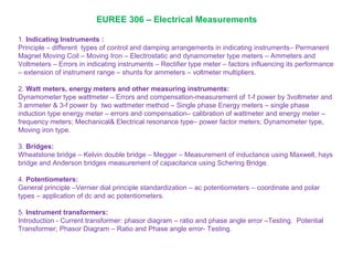


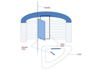


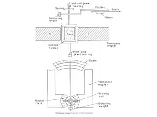
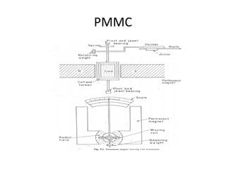
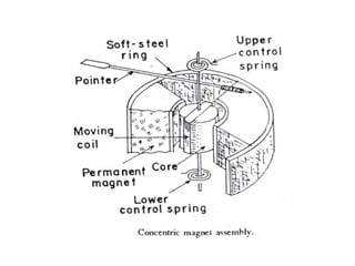
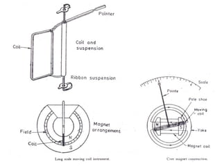
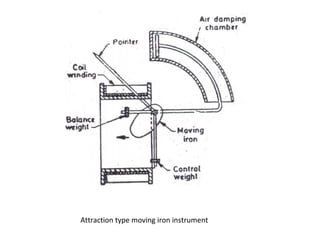
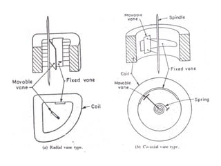
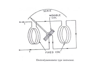
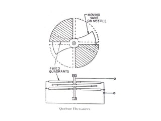
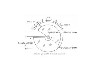
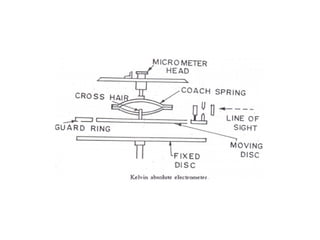
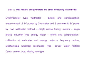

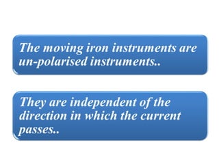


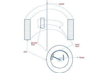


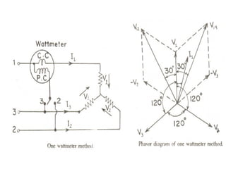
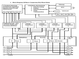
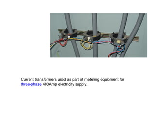
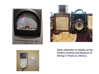
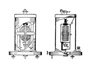
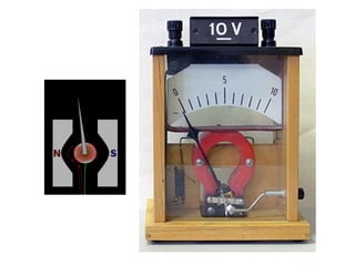
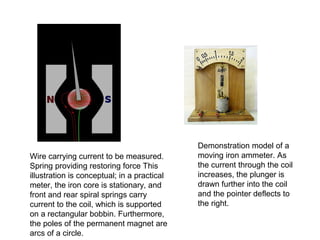
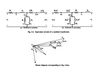
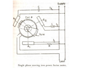
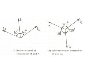
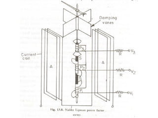
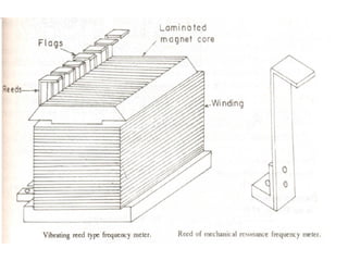

This document discusses electrical measurements and various types of measuring instruments. It covers topics like indicating instruments, wattmeters, energy meters, bridges, potentiometers and instrument transformers. Specifically, it describes the principles and components of instruments like permanent magnet moving coil meters, moving iron meters, dynamometer wattmeters and single phase induction energy meters. It also discusses bridges like Wheatstone bridge and potentiometers for electrical measurements. Measurement of parameters like frequency, power factor using different types of meters is presented.


![ELECTRICAL MEASUREMENT & MEASURING INSTRUMENTS [Emmi- (NEE-302) -unit-1]](https://cdn.slidesharecdn.com/ss_thumbnails/emmi-nee-302-unit-1-170607090405-thumbnail.jpg?width=640&height=640&fit=bounds)