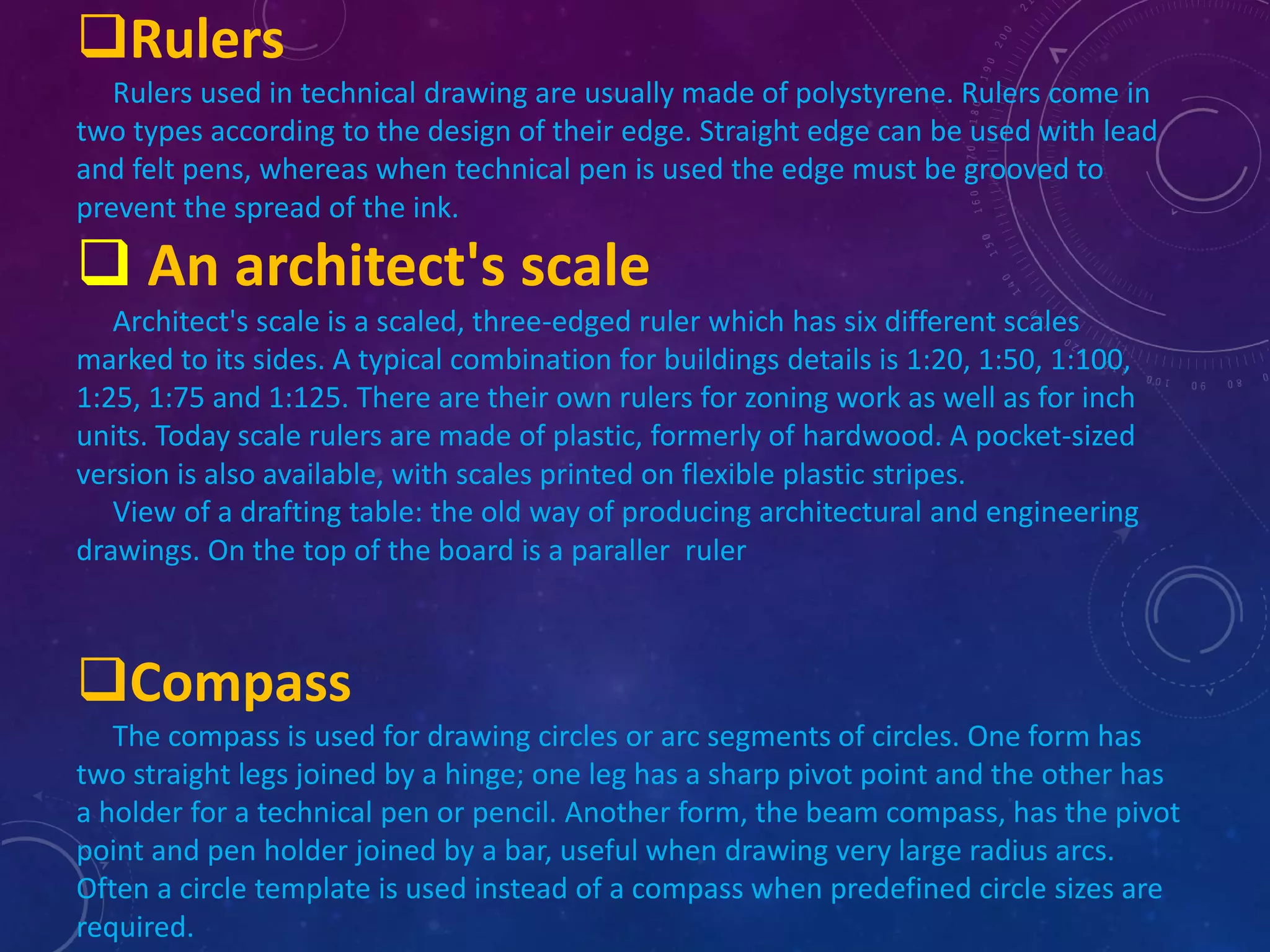
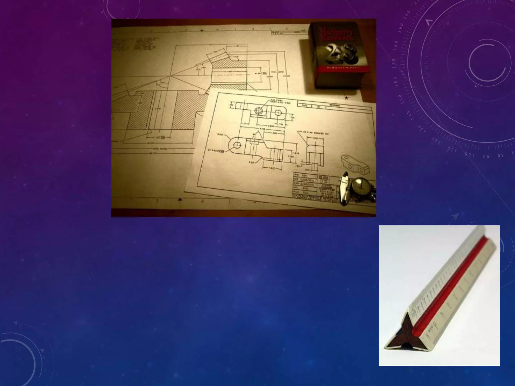
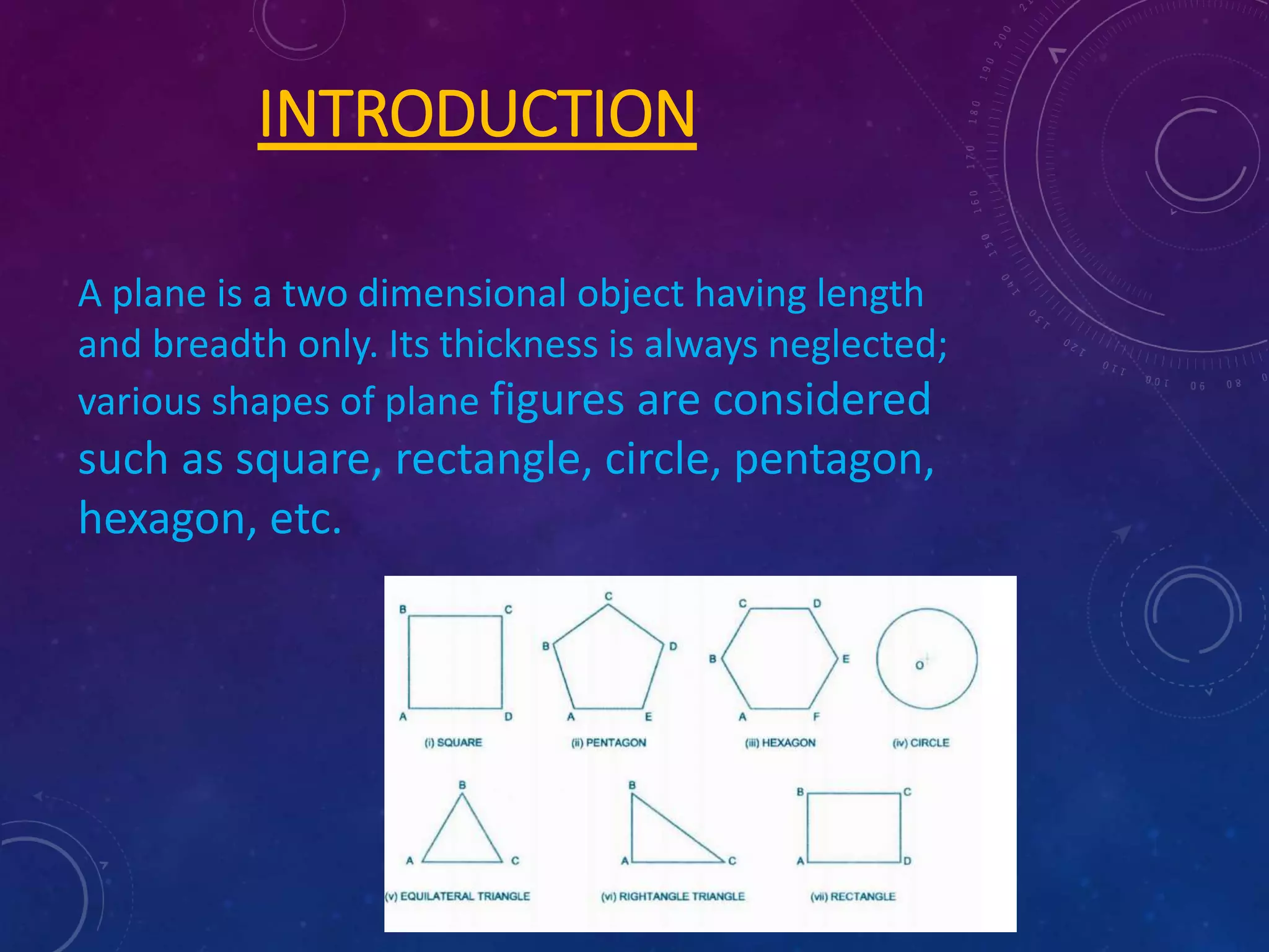
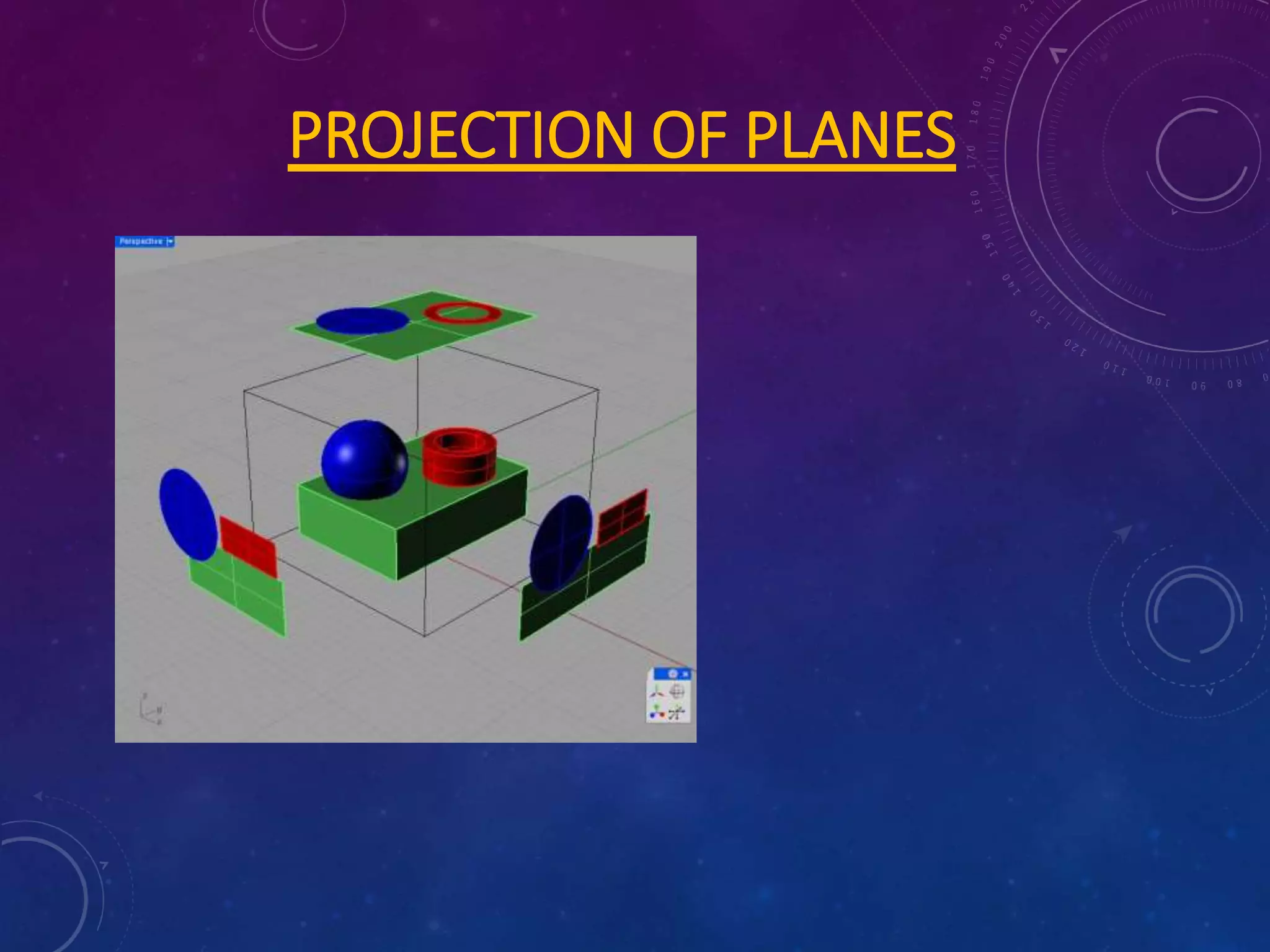
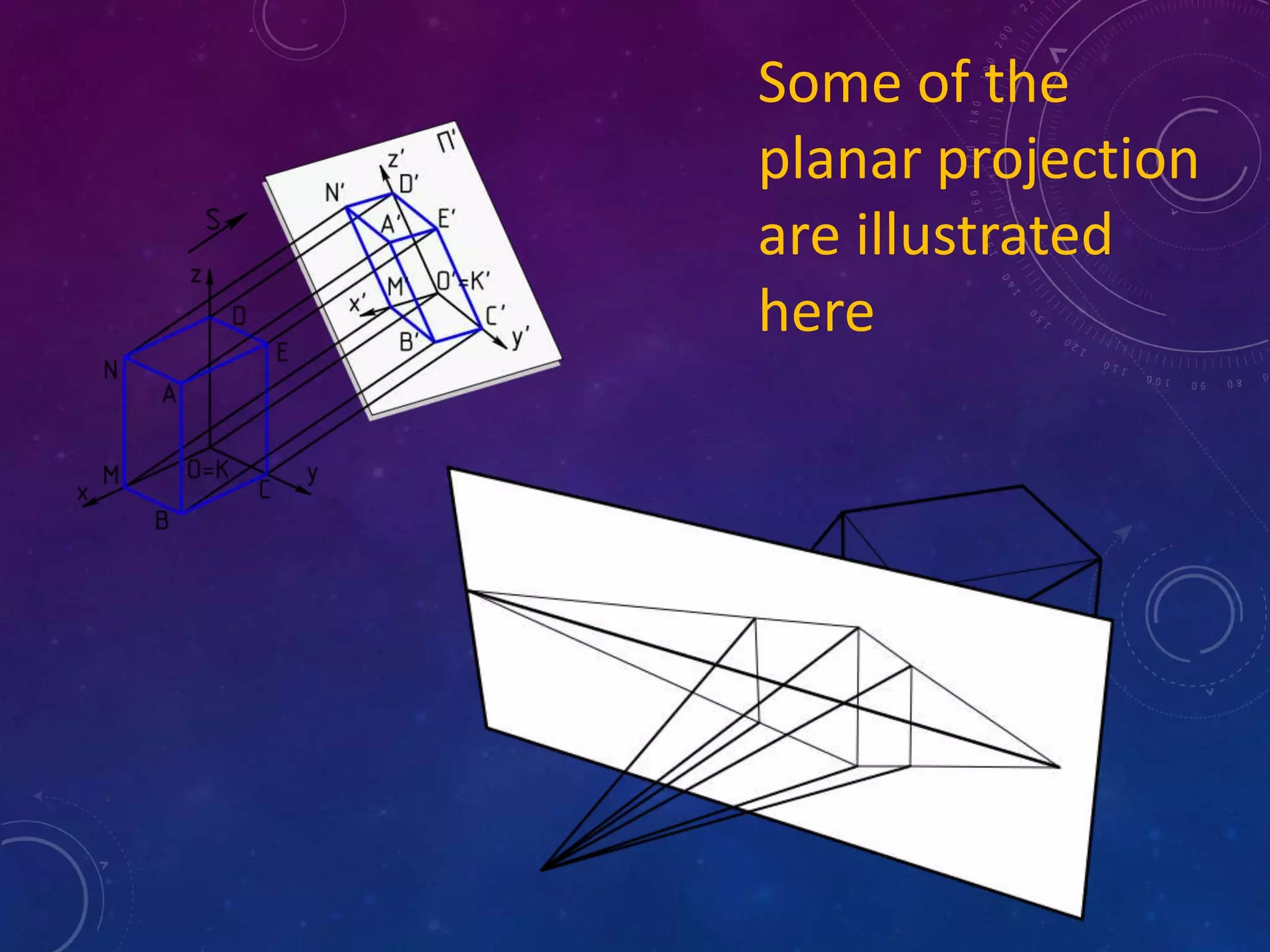
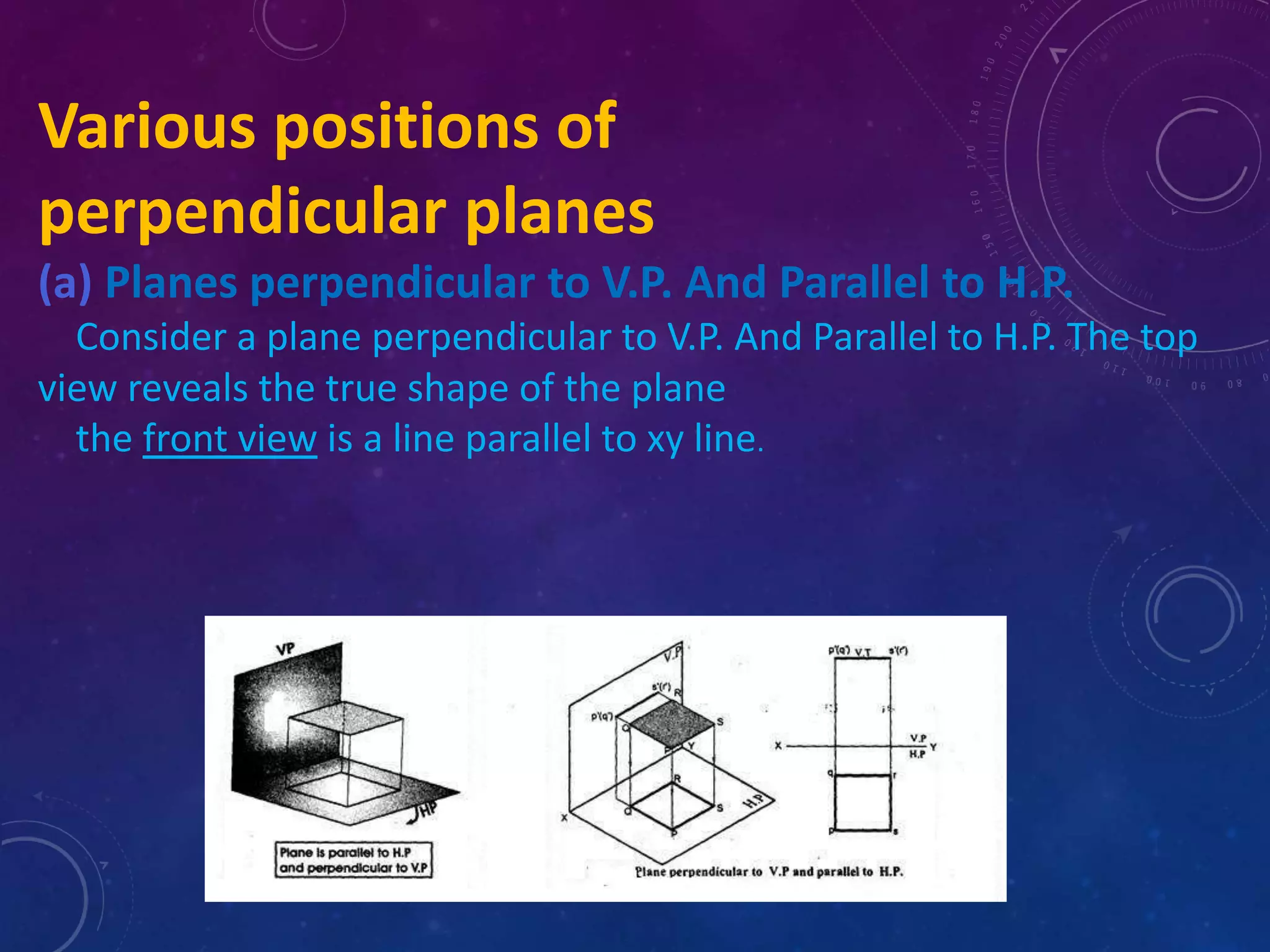
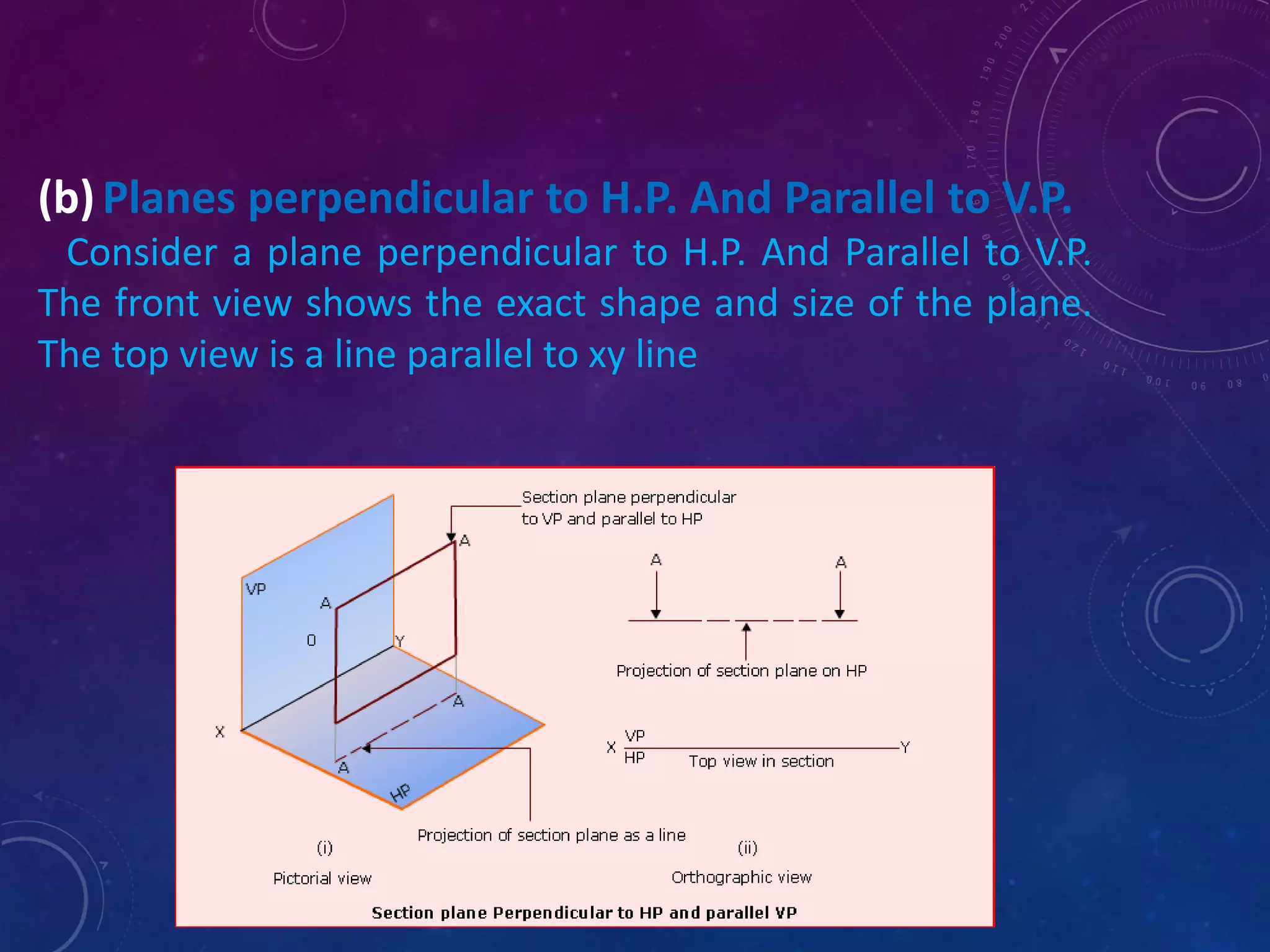
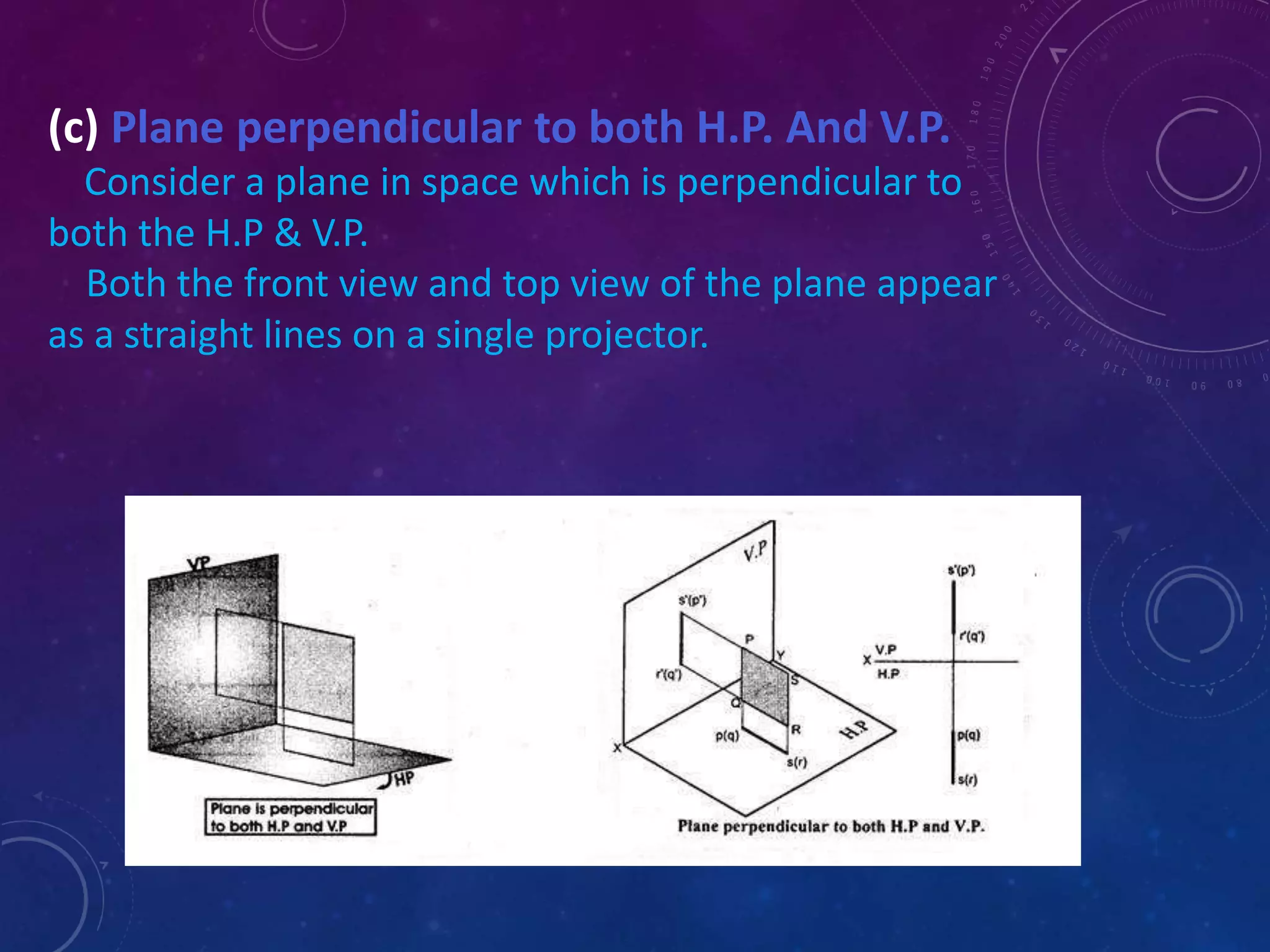
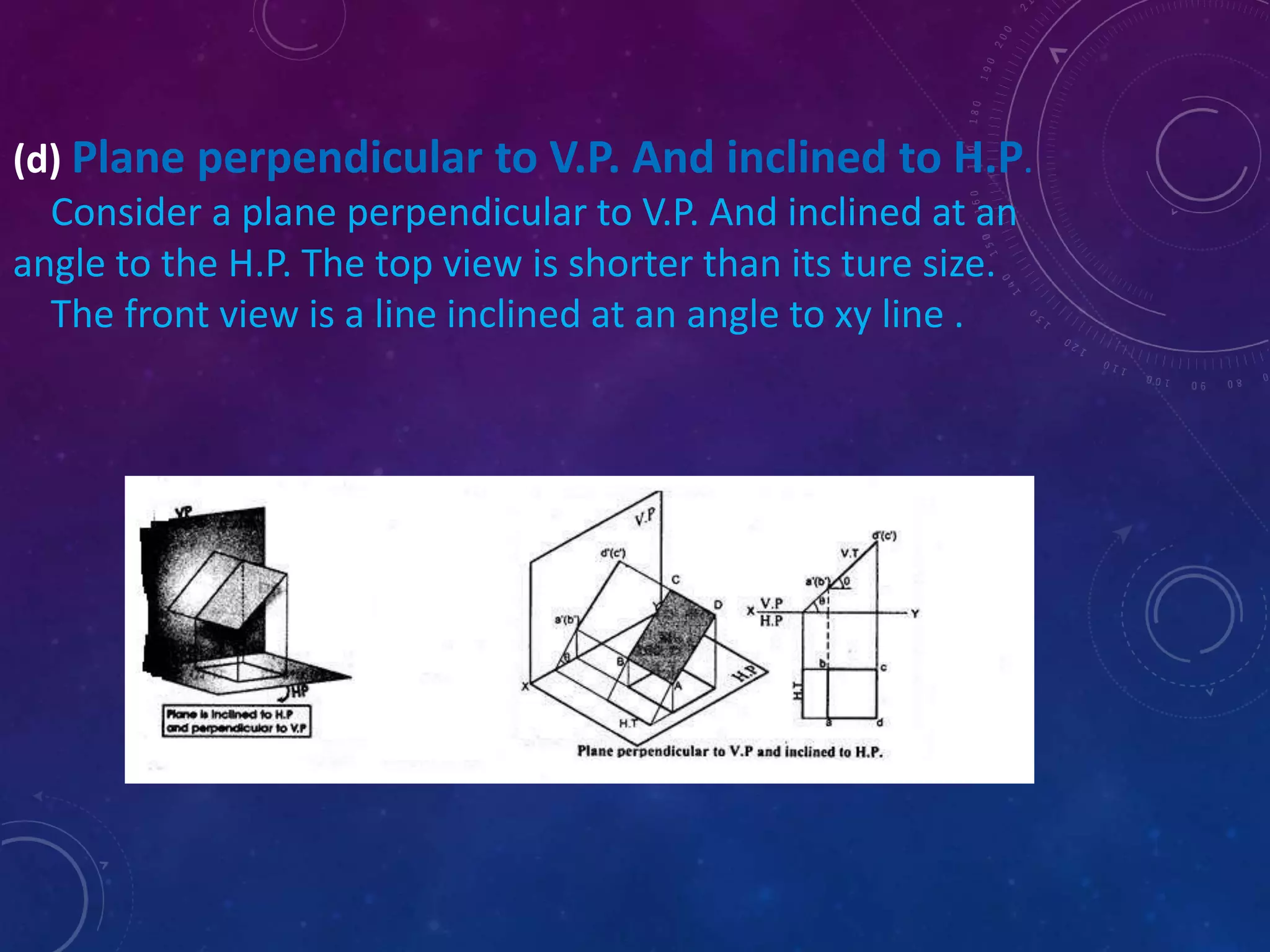
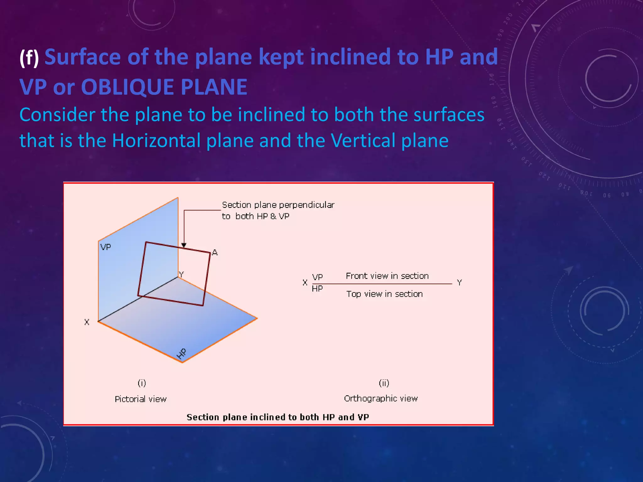
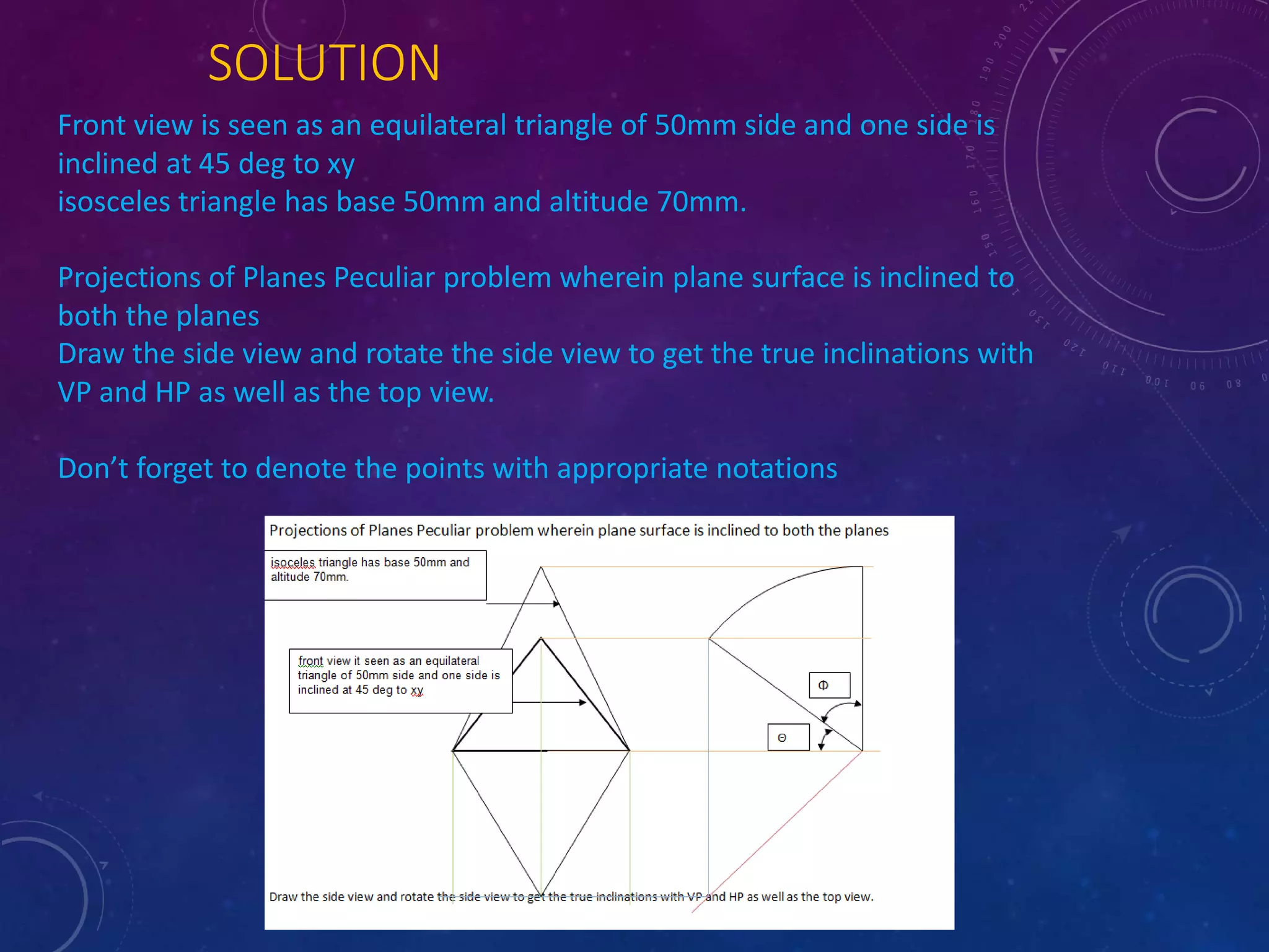
Projection Of Planes 
Created By:- Viraj shah
Basic tools For EG 
Pens 
Traditional and typical pens used for technical drawing 
are pencils and technical pens. 
Pencils in use are usually mechanical pencils with a standard lead 
thickness. General line widths are 0.18 mm, 0.25 mm, 0.5 mm and 
0.7 mm. Hardness varies usually from HB to 2H. Softer lead gives a better 
contrast, but harder lead gives more accurate track. 
 Drawing board 
The drawing board is an essential tool. Paper will be attached and 
kept straight and still, so that the drawing can be done with accuracy. 
Generally, different kind of assistance rulers are used in drawing. The 
drawing board is usually mounted to a floor pedestal in which the board 
turns to a different position, and also its height can be adjustable. Smaller 
drawing boards are produced for table-top use. In the 18th and 19th 
centuries, drawing paper was dampened and then its edges glued to the 
drawing board. After drying the paper would be flat and smooth. The 
completed drawing was cut free. Paper could also be secured to the 
drawing board with pins. More recent practice is to use self-adhesive tape 
to secure paper to the board.
•T-square 
A T-square is a straightedge which uses the edge of the drawing board as a 
support. It is used with the drafting board to draw horizontal lines and to align other 
drawing instruments. Wood, metal, or plastic triangles with 30 and 60 degree angles 
or with two 45 degree angles are used to speed drawing of lines at these commonly 
used angles. Also in use are a continuously adjustable 0-90 degrees protractor. An 
alternative to the T-square is the parallel bar which is permanently attached to the 
drawing board. It has a set of cables and pulleys to allow it to be positioned anywhere 
on the drawing surface while stil remaining parallel to the bottom of the board. The 
drafting machine replaces the T-square and triangles. 
•Drafting machine 
A drafting machine is a device which is mounted to the drawing board. It has 
rulers whose angles can be precisely adjusted with a controlling mechanism. There 
are two main types of apparatus: an arm-type parallelogram apparatus based on a 
hinged arm; and a track-type apparatus which moves on a rail mounted to the top of 
the drawing board. The accuracy of the arm type apparatus is better in the middle of 
the board, decreasing towards the edges, whereas a track machine has a constant 
accuracy over the whole board. The drawing head of a track-type drafting machine 
slides on bearings in a vertical rail, which in turn is moved along a horizontal, top-mounted 
rail. Both apparatus types have an adjustable drawing-head with rules 
attached to a protractor scale so that the angle of the rules may be adjusted.
Rulers 
Rulers used in technical drawing are usually made of polystyrene. Rulers come in 
two types according to the design of their edge. Straight edge can be used with lead 
and felt pens, whereas when technical pen is used the edge must be grooved to 
prevent the spread of the ink. 
 An architect's scale 
Architect's scale is a scaled, three-edged ruler which has six different scales 
marked to its sides. A typical combination for buildings details is 1:20, 1:50, 1:100, 
1:25, 1:75 and 1:125. There are their own rulers for zoning work as well as for inch 
units. Today scale rulers are made of plastic, formerly of hardwood. A pocket-sized 
version is also available, with scales printed on flexible plastic stripes. 
View of a drafting table: the old way of producing architectural and engineering 
drawings. On the top of the board is a paraller ruler 
Compass 
The compass is used for drawing circles or arc segments of circles. One form has 
two straight legs joined by a hinge; one leg has a sharp pivot point and the other has 
a holder for a technical pen or pencil. Another form, the beam compass, has the pivot 
point and pen holder joined by a bar, useful when drawing very large radius arcs. 
Often a circle template is used instead of a compass when predefined circle sizes are 
required.
INTRODUCTION 
A plane is a two dimensional object having length 
and breadth only. Its thickness is always neglected; 
various shapes of plane figures are considered 
such as square, rectangle, circle, pentagon, 
hexagon, etc.
PROJECTION OF PLANES
Some of the 
planar projection 
are illustrated 
here
A Plane is a two dimensional entity having only length 
and breadth with negligible thickness which is 
considered as zero. 
TYPES OF PLANES 
Planes may be divided as two main types. They are 
(I) Perpendicular Planes 
(II) Oblique Planes. 
Perpendicular Planes 
Planes which are perpendicular to any one of the 
principal planes of projection are called as 
perpendicular planes. These planes may be inclined or 
parallel to the other principal plane.
Various positions of 
perpendicular planes 
(a) Planes perpendicular to V.P. And Parallel to H.P. 
Consider a plane perpendicular to V.P. And Parallel to H.P. The top 
view reveals the true shape of the plane 
the front view is a line parallel to xy line.
(b) Planes perpendicular to H.P. And Parallel to V.P. 
Consider a plane perpendicular to H.P. And Parallel to V.P. 
The front view shows the exact shape and size of the plane. 
The top view is a line parallel to xy line
(c) Plane perpendicular to both H.P. And V.P. 
Consider a plane in space which is perpendicular to 
both the H.P & V.P. 
Both the front view and top view of the plane appear 
as a straight lines on a single projector.
(d) Plane perpendicular to V.P. And inclined to H.P. 
Consider a plane perpendicular to V.P. And inclined at an 
angle to the H.P. The top view is shorter than its ture size. 
The front view is a line inclined at an angle to xy line .
(e) Plane perpendicular to H.P. And inclined to V.P. 
Consider a plane perpendicular to the H.P. And inclined at 
an angle to the V.P. The front view is shorter than its true 
size. 
The top view is a line inclined at an angle to xy line.
(f) Surface of the plane kept inclined to HP and 
VP or OBLIQUE PLANE 
Consider the plane to be inclined to both the surfaces 
that is the Horizontal plane and the Vertical plane
Example 
A plate having a shape of an isosceles 
triangle has base 50mm and altitude 
70mm. It is so placed that in the front 
view it seen as an equilateral triangle of 
50mm side and one side is inclined at 45 
deg to xy .
SOLUTION 
Front view is seen as an equilateral triangle of 50mm side and one side is 
inclined at 45 deg to xy 
isosceles triangle has base 50mm and altitude 70mm. 
Projections of Planes Peculiar problem wherein plane surface is inclined to 
both the planes 
Draw the side view and rotate the side view to get the true inclinations with 
VP and HP as well as the top view. 
Don’t forget to denote the points with appropriate notations
Thank you

Eg.ppt

  • 1.
    Projection Of Planes Created By:- Viraj shah
  • 2.
    Basic tools ForEG Pens Traditional and typical pens used for technical drawing are pencils and technical pens. Pencils in use are usually mechanical pencils with a standard lead thickness. General line widths are 0.18 mm, 0.25 mm, 0.5 mm and 0.7 mm. Hardness varies usually from HB to 2H. Softer lead gives a better contrast, but harder lead gives more accurate track.  Drawing board The drawing board is an essential tool. Paper will be attached and kept straight and still, so that the drawing can be done with accuracy. Generally, different kind of assistance rulers are used in drawing. The drawing board is usually mounted to a floor pedestal in which the board turns to a different position, and also its height can be adjustable. Smaller drawing boards are produced for table-top use. In the 18th and 19th centuries, drawing paper was dampened and then its edges glued to the drawing board. After drying the paper would be flat and smooth. The completed drawing was cut free. Paper could also be secured to the drawing board with pins. More recent practice is to use self-adhesive tape to secure paper to the board.
  • 4.
    •T-square A T-squareis a straightedge which uses the edge of the drawing board as a support. It is used with the drafting board to draw horizontal lines and to align other drawing instruments. Wood, metal, or plastic triangles with 30 and 60 degree angles or with two 45 degree angles are used to speed drawing of lines at these commonly used angles. Also in use are a continuously adjustable 0-90 degrees protractor. An alternative to the T-square is the parallel bar which is permanently attached to the drawing board. It has a set of cables and pulleys to allow it to be positioned anywhere on the drawing surface while stil remaining parallel to the bottom of the board. The drafting machine replaces the T-square and triangles. •Drafting machine A drafting machine is a device which is mounted to the drawing board. It has rulers whose angles can be precisely adjusted with a controlling mechanism. There are two main types of apparatus: an arm-type parallelogram apparatus based on a hinged arm; and a track-type apparatus which moves on a rail mounted to the top of the drawing board. The accuracy of the arm type apparatus is better in the middle of the board, decreasing towards the edges, whereas a track machine has a constant accuracy over the whole board. The drawing head of a track-type drafting machine slides on bearings in a vertical rail, which in turn is moved along a horizontal, top-mounted rail. Both apparatus types have an adjustable drawing-head with rules attached to a protractor scale so that the angle of the rules may be adjusted.
  • 6.
    Rulers Rulers usedin technical drawing are usually made of polystyrene. Rulers come in two types according to the design of their edge. Straight edge can be used with lead and felt pens, whereas when technical pen is used the edge must be grooved to prevent the spread of the ink.  An architect's scale Architect's scale is a scaled, three-edged ruler which has six different scales marked to its sides. A typical combination for buildings details is 1:20, 1:50, 1:100, 1:25, 1:75 and 1:125. There are their own rulers for zoning work as well as for inch units. Today scale rulers are made of plastic, formerly of hardwood. A pocket-sized version is also available, with scales printed on flexible plastic stripes. View of a drafting table: the old way of producing architectural and engineering drawings. On the top of the board is a paraller ruler Compass The compass is used for drawing circles or arc segments of circles. One form has two straight legs joined by a hinge; one leg has a sharp pivot point and the other has a holder for a technical pen or pencil. Another form, the beam compass, has the pivot point and pen holder joined by a bar, useful when drawing very large radius arcs. Often a circle template is used instead of a compass when predefined circle sizes are required.
  • 8.
    INTRODUCTION A planeis a two dimensional object having length and breadth only. Its thickness is always neglected; various shapes of plane figures are considered such as square, rectangle, circle, pentagon, hexagon, etc.
  • 9.
  • 10.
    Some of the planar projection are illustrated here
  • 11.
    A Plane isa two dimensional entity having only length and breadth with negligible thickness which is considered as zero. TYPES OF PLANES Planes may be divided as two main types. They are (I) Perpendicular Planes (II) Oblique Planes. Perpendicular Planes Planes which are perpendicular to any one of the principal planes of projection are called as perpendicular planes. These planes may be inclined or parallel to the other principal plane.
  • 12.
    Various positions of perpendicular planes (a) Planes perpendicular to V.P. And Parallel to H.P. Consider a plane perpendicular to V.P. And Parallel to H.P. The top view reveals the true shape of the plane the front view is a line parallel to xy line.
  • 13.
    (b) Planes perpendicularto H.P. And Parallel to V.P. Consider a plane perpendicular to H.P. And Parallel to V.P. The front view shows the exact shape and size of the plane. The top view is a line parallel to xy line
  • 14.
    (c) Plane perpendicularto both H.P. And V.P. Consider a plane in space which is perpendicular to both the H.P & V.P. Both the front view and top view of the plane appear as a straight lines on a single projector.
  • 15.
    (d) Plane perpendicularto V.P. And inclined to H.P. Consider a plane perpendicular to V.P. And inclined at an angle to the H.P. The top view is shorter than its ture size. The front view is a line inclined at an angle to xy line .
  • 16.
    (e) Plane perpendicularto H.P. And inclined to V.P. Consider a plane perpendicular to the H.P. And inclined at an angle to the V.P. The front view is shorter than its true size. The top view is a line inclined at an angle to xy line.
  • 17.
    (f) Surface ofthe plane kept inclined to HP and VP or OBLIQUE PLANE Consider the plane to be inclined to both the surfaces that is the Horizontal plane and the Vertical plane
  • 18.
    Example A platehaving a shape of an isosceles triangle has base 50mm and altitude 70mm. It is so placed that in the front view it seen as an equilateral triangle of 50mm side and one side is inclined at 45 deg to xy .
  • 19.
    SOLUTION Front viewis seen as an equilateral triangle of 50mm side and one side is inclined at 45 deg to xy isosceles triangle has base 50mm and altitude 70mm. Projections of Planes Peculiar problem wherein plane surface is inclined to both the planes Draw the side view and rotate the side view to get the true inclinations with VP and HP as well as the top view. Don’t forget to denote the points with appropriate notations
  • 21.