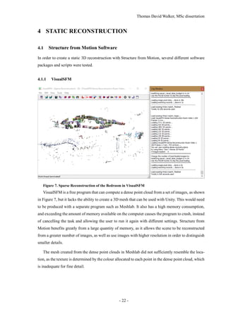
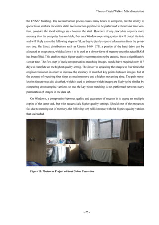
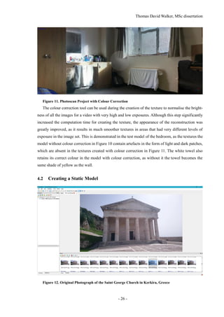
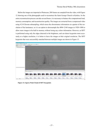
This document is the MSc dissertation of Thomas David Walker from the University of Surrey. It details his work on creating 3D environments from videos for virtual reality. The dissertation includes background on structure from motion reconstruction and object tracking. It describes calibrating cameras, reconstructing static scenes, extracting dynamic objects as billboards, and implementing the results in Unity. The experiments reconstructed parts of the British Museum to demonstrate indoor and outdoor environments populated with moving people. The dissertation concludes the objectives were achieved but improving billboard motion was left for future work.


![Thomas David Walker, MSc dissertation
- 11 -
1 INTRODUCTION
1.1 Background and Context
Virtual reality has progressed to the point that consumer headsets can support realistic interactive
environments, due to advancements in 3D rendering, high resolution displays and positional tracking.
However, it is still difficult to create content for VR that is based on the real world. Omnidirectional
cameras such as those used by the BBC’s Click team [1] produce 360° videos from a stationary
position by stitching together the images from six cameras [2], but the lack of stereoscopy (depth
perception) and free movement make them inadequate for a full VR experience. These can only be
achieved by creating a 3D model that accurately depicts the location, including the moving objects
that are present in the video.
Astatic model of a scene can be produced from a set of photographs using Structure from Motion,
which creates a 3D point cloud by matching SIFT (Scale-Invariant Feature Transform) keypoints
between pairs of images taken from different positions [3]. Only stationary objects produce keypoints
that remain consistent as the camera pose is changed, so the keypoints of moving objects are dis-
carded from the reconstruction.
Many of the locations that can be modelled with this technique appear empty without any moving
objects, such as vehicles or crowds of people, so these are extracted with a separate program. Moving
objects can be removed from a video by recording it with a stationary camera, then averaging the
frames together to create a median image. This image is subtracted from each frame of the original
video to create a set of difference images that contain only the moving objects in the scene [4].
1.2 Scope and Objectives
The first objective of the project is to use Structure from Motion to create a complete 3D model of a
scene from a set of images. The second objective, which contains the most significant contribution
to the field of reconstruction, is to extract the dynamic objects from the scene such that each object
can be represented as a separate animated billboard. The final objective is to combine the static and
dynamic elements in Unity to allow the location to be viewed through a virtual reality headset.
1.3 Achievements
Two video cameras have been tested for the static reconstruction in the software packages VisualSFM
and Agisoft Photoscan, and scripts for object tracking have been written in Matlab. The model and
billboards have been implemented in Unity to allow the environment to be populated with billboards
that play animations of the people present in the original videos. A complete guide to using the soft-
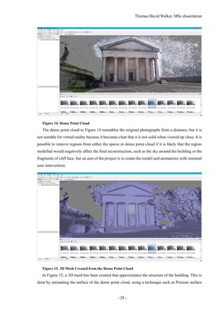
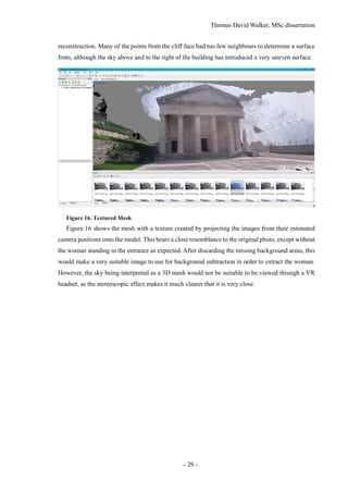
ware and scripts have been written in the appendices.](https://image.slidesharecdn.com/52b1f858-470a-420c-adac-c44d0dbee585-161026140127/85/Dissertation-11-320.jpg)
![Thomas David Walker, MSc dissertation
- 12 -
Test footage from locations such as a bedroom and the front of the University of Surrey’s Austin
Pearce building were used to highlight the strengths and weaknesses of the static reconstruction.
Large surfaces lacking in detail such as walls, floors, and clear skies do not generate keypoints that
can be matched between images, which leaves holes in the 3D model.
The aim of the dynamic reconstruction was to create a script that can identify, track, and extract
the moving objects in a video, and create an animation for a billboard that contains a complete image
of the object without including additional clutter. This required the ability to distinguish separate
moving objects as well as track them while they are occluded. Connected components were created
from the difference image, although this is a morphological operation that has no understanding on
the depth in the scene. This often resulted in overlapping objects being considered as a single object.
It is also unreliable for tracking an entire person as a single object, so a separate script was created
that specialises in identifying people.
Once all of the objects have been identified in the frame, tracking is performed in order to deter-
mine their movement over time. One of the biggest challenges in tracking is occlusion, which is the
problem of an object moving in front of another one, partially or completely obscuring it. This was
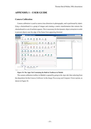
solved with the implementation of the Kalman filter [5], which is an object-tracking algorithm that
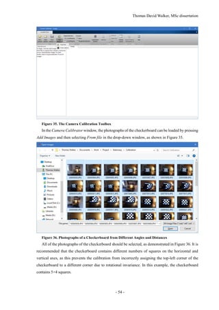
considers both the observed position and the estimated position of each object to allow it to predict
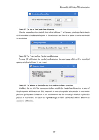
where an object is located during the frames where it cannot be visually identified.
The dynamic objects extracted from the video are only 2D, so they are applied to ‘billboards’that
rotate to face the viewer to provide the illusion of being 3D. They can also cast shadows on to the
environment by using a second invisible billboard that always faces towards the main light source.
Although the billboards are animated using their appearance from the video, their movement could
also be approximated to match their position in each video frame. In order to estimate the object’s
depth in the scene from a single camera, an assumption would be made that the object’s position is
at the point where the lowest pixel touches the floor of the 3D reconstruction. This would be an
adequate estimate for grounded objects such as people or cars, but not for anything airborne such as
birds or a person sprinting. However, this was not able to be implemented.
1.4 Overview of Dissertation
This dissertation contains a literature review that explains the established solutions for Structure from
Motion and object tracking, and an outline of the method that will allow these to be combined to
support dynamic objects. This is followed by an evaluation and discussion of the results and a sum-
mary of the findings and limitations of the study, with suggestions for future research. The appendices
contain a complete guide to use the software and scripts to replicate the work carried out in this
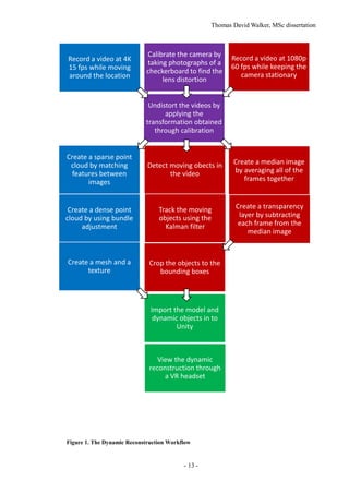
project, in order to allow it to be developed further. The workflow is shown in Figure 1.](https://image.slidesharecdn.com/52b1f858-470a-420c-adac-c44d0dbee585-161026140127/85/Dissertation-12-320.jpg)
![Thomas David Walker, MSc dissertation
- 14 -
2 STATE-OF-THE-ART
2.1 Introduction
The methods of applying Structure from Motion to create static models of real-world objects from
photographs has advanced significantly in recent years, but this project aims to expand the technique
to allow animated objects created from videos to be used alongside it. This requires the use of object
identification and tracking algorithms to effectively separate the moving objects from the back-
ground.
2.2 Structure from Motion for Static Reconstruction
The Structure from Motion pipeline is comprehensively covered in the books Digital Representations
of the Real World [6] and Computer Vision: Algorithms and Applications [7]. However, there are
many applications and modifications to the technique that have been published which contribute to
the aims of this project.
An early method of static reconstruction was achieved by Microsoft with Photosynth in 2008 [8].
Instead of creating a 3D mesh from the images, they are stitched together using the photographs that
are the closest match to the current view. This results in significant amounts of warping during cam-
era movement, and dynamic objects that were present in the original photographs remain visible at
specific angles. It also provides a poor reconstruction of views that were not similar to any contained
in the image set, such as from above.
The following year, the entire city of Rome was reconstructed as a point cloud in a project from
the University of Washington called ‘Building Rome in a Day’ [9]. This demonstrated the use of
Structure for Motion both for large-scale environments, as well as with the use of communally-
sourced photographs from uncalibrated cameras. However, the point cloud did not have a high
enough density to appear solid unless observed from very far away. A 3D mesh created from the
point cloud would be a superior reconstruction, although it would be difficult to create a texture from
photographs under many different lighting conditions that still looks consistent.
DTAM (Dense Tracking and Mapping in Real-Time) is a recent modification of Structure from
Motion that uses the entire image to estimate movement, instead of keypoint tracking [10]. This is
made feasible by the use of GPGPU (General-Purpose computing on Graphics Processing Units),
which allows programming to be performed on graphics cards with their support for many parallel
processes, as opposed to the CPU (Central Processing Unit) where the number of concurrent tasks is
limited to the number of cores and threads. DTAM is demonstrated to be more effective in scenes
with motion blur, as these create poor keypoints but high visual correspondence [11].](https://image.slidesharecdn.com/52b1f858-470a-420c-adac-c44d0dbee585-161026140127/85/Dissertation-14-320.jpg)
![Thomas David Walker, MSc dissertation
- 15 -
2.3 Object Tracking
Tracking objects continues to be a challenge for computer vision, with changing appearance and
occlusion adding significant complexity. There have been many algorithms designed to tackle this
problem, with different objectives and constraints.
Long-term tracking requires the algorithm to be robust to changes in illumination and angle. LT-
FLOtrack (Long-Term FeatureLess Object tracker) is a technique that tracks edge-based features to
reduce the dependence on the texture of the object [12]. This incorporates unsupervised learning in
order to adapt the descriptor over time, as well as a Kalman filter to allow an object to be re-identified
if it becomes occluded. The position and identity of an object is determined by a pair of confidence
scores, the first from measuring the current frame, and the second being an estimate based on previ-
ous results. If the object is no longer present in the frame, the confidence score of its direct
observation becomes lower than the confidence of the tracker, so the estimated position is used in-
stead. If the object becomes visible again, and it is close to its predicted position, then it is determined
to be the same object.
The algorithm used in TMAGIC (Tracking, Modelling And Gaussian-process Inference Com-
bined) is designed to track and model the 3D structure of an object that is moving relative to the
camera and to the environment [13]. The implementation requires the user to create a bounding box
around the object on the first frame, so it would need to be modified to support objects that appear
during the video. Although this can create 3D dynamic objects instead of 2D billboards, the object
would need to be seen from all sides to create an adequate model, and it is only effective for rigid
objects such as vehicles, and not objects with more complex movements such as pedestrians.
Although one of the aims of the project is to detect and track arbitrary moving objects, incorpo-
rating pre-trained trackers for vehicles and pedestrians could benefit the reconstruction. ‘Meeting in
the Middle: A Top-down and Bottom-up Approach to Detect Pedestrians’ [14] explores the use of
fuzzy first-order logic as an alternative to the Kalman filter, and the MATLAB code from MathWorks
for tracking pedestrians from a moving car [15] is used as a template for the object tracking prior to
the incorporation of the static reconstruction.
Many of the video-tracking algorithms only track the location of an object in the two-dimensional
reference frame of the original video. Tracking the trajectory of points in three dimensions is
achieved in the paper ‘Joint Estimation of Segmentation and Structure from Motion’ [16]. Other re-
ports that relate to this project include ‘Exploring Causal Relationships in Visual Object Tracking’
[17], ‘Dense Rigid Reconstruction from Unstructured Discontinuous Video’ [18], and ‘Tracking the
Untrackable: How to Track When Your Object Is Featureless’ [19].](https://image.slidesharecdn.com/52b1f858-470a-420c-adac-c44d0dbee585-161026140127/85/Dissertation-15-320.jpg)
![Thomas David Walker, MSc dissertation
- 16 -
2.4 Virtual Reality
2016 is the year that three major virtual reality headsets are released, which are the Oculus Rift, HTC
Vive, and PlayStation VR. These devices are capable of tracking the angle and position of the head
with less than a millisecond of delay, using both accelerometers within the headset, as well as posi-
tion-tracking cameras [20] [21]. The Vive headset allows the user to move freely anywhere within
the area covered by the position-tracking cameras, and have this movement replicated within the
game.
The HTC Vive was tested with a prototype build of a horror game called ‘A Chair in a Room’,
created in Unity by a single developer called Ryan Bousfield. In order to allow the player to move
between rooms without walking into a wall or out of the range of the tracking cameras, he developed
a solution where interacting with a door places the player in the next room but facing the door they
came in, so they’d turn around to explore the new room. This allows any number of rooms to be
connected together, making it possible to explore an entire building.
Unity is a game creation utility with support for many of the newest virtual reality headsets, al-
lowing it to render a 3D environment with full head and position tracking. The scene’s lighting and
scale would need to be adjusted in order to be fully immersive. Although the static reconstruction
can easily be imported into Unity, it is essential that the model is oriented correctly so that the user
is standing on the floor, and the model is not at an angle. In VR, it is important that the scale of the
environment is correct, which is most easily achieved by including an object of known size in the
video, such as a metre rule.](https://image.slidesharecdn.com/52b1f858-470a-420c-adac-c44d0dbee585-161026140127/85/Dissertation-16-320.jpg)
![Thomas David Walker, MSc dissertation
- 18 -
An advantage of using photographs is the ability to take raw images, which are unprocessed and
uncompressed, allowing a custom demosaicing algorithm and more advanced noise reduction tech-
niques to be used [22] [23]. The image sensor in a camera is typically overlaid with a set of colour
filters arranged in a Bayer pattern, which ensures that each sensor only detects either red, green or
blue light. Demosaicing is the method used to reconstruct a full colour image at the same resolution
as the original sensor, by interpolating the missing colour values. Unlike frames extracted from a
video, photographs also contain metadata that includes the intrinsic parameters of the camera, such
as the focal length and shutter speed, which allows calibration to be performed more accurately as
these would not need to be estimated.
Before the calibration takes place, the image enhancement features are disabled in order to obtain
images that are closer to what the sensor detected. These settings are typically designed to make the
images more appealing to look at, but also makes them less accuratefor use in Structure from Motion.
The colour correction and sharpening settings must be disabled, and the white balance should be set
to Cam RAW, which is an industry standard. The ISO limit, i.e. the gain, should be fixed at a specific
value determined by the scene, as the lowest value of 400 will have the least noise at the expense of
a darker image. Noise reduction is an essential precaution for Structure from Motion, but keypoints
can be missed entirely if the image is too dark.
The GoPro supports a continuous photo mode that can take photographs with a resolution of 12.4
Megapixels at up to 10 times per second, but the rate at which the images are taken is bottlenecked
by the transfer speed of the microSD card. In a digital camera, the data from the image sensor is held
in RAM before it is transferred to the microSD card, in order to allow additional processing to be
performed such as demosaicing and compression. However, raw images have no compression and
therefore a much higher file size, which means they will take longer to transfer to the microSD card
than the rate at which they can be taken. Therefore, the camera can only take photographs at a rate
of 10 images per second before the RAM has been filled, at which point the rate of capture becomes
significantly reduced. However, as the read and write speed of microSD cards are continually in-
creasing, the use of high resolution raw images will be possible for future development.
3.2 Capturing Video with the GoPro Hero3+
For the static reconstruction, resolution is a higher priority than frame rate, as it allows for smaller
and more distant keypoints to be distinguished. Only a fraction of the frames from a video can be
used in Photoscan as it slows down considerably if the image set cannot fit within the computer’s
memory [24]. It is not possible to record video at both the highest resolution and frame rate supported
by the camera, due to limitations in the speed of the CMOS (Complementary metal–oxide–semicon-
ductor) sensor, the data transfer rate of the microSD card, and the processing power required to
compress the video. However, separating the static and dynamic reconstructions allowed the most](https://image.slidesharecdn.com/52b1f858-470a-420c-adac-c44d0dbee585-161026140127/85/Dissertation-18-320.jpg)
![Thomas David Walker, MSc dissertation
- 19 -
suitable setting to be used for each recording. For the static reconstruction, the video was recorded
at 3860×2160 pixels at 15 frames per second. At this aspect ratio the field of view is 69.5° vertically,
125.3° horizontally, and 139.6° diagonally, due to the focal length being only 14 mm.
There are several disadvantages to recording the footage as a video compared to a set of photo-
graphs. It is impossible to obtain the raw images from a video, before any post-processing such as
white balancing, gamma correction, or noise reduction has been performed, and the images extracted
from the video have also been heavily compressed. The coding artefacts may not be visible to a
person when played back at full speed, but each frame has spatial and temporal artefacts that can
negatively affect the feature detection. While video footage is being recorded, the focus and exposure
are automatically adjusted to improve the visibility, although this inconsistency also leads to poor
matching between images. Colour correction can be used in Photoscan to account for this, by nor-
malising the brightness of every image in the dataset.
The image sensor used in the GoPro camera is a CMOS sensor with a pixel pitch of 1.55 µm. One
of the disadvantages of this type of sensor is the rolling shutter effect, where rows of pixels are
sampled sequentially, resulting in a temporal distortion if the camera is moved during the capture of
the image. This can manifest even at walking speed, and unless the camera is moving at a consistent
speed and at the same height and orientation, it is not possible to counteract the exact amount of
distortion. The same effect occurs in the Sony Xperia Z3 Compact camera, which suggests that it
also uses a CMOS sensor.
3.3 Calibration of the GoPro Hero3+ and the Sony Xperia Z3 Compact
In addition to the GoPro, the camera within the Sony Xperia Z3 Compact mobile phone was used
in testing for its ability to record 4K video at 30 fps. This could be used to create higher resolution
dynamic objects, although the smaller field of view would require more coverage of the scene to
make the static reconstruction. It is also possible to take up to 20.7 Megapixel photographs with an
ISO limit of 12,800 [25], although it cannot take uncompressed or raw images.
The most significant difference between the two cameras is the GoPro’s wide field of view, which
is an attribute that causes barrel distortion that increases towards the sides of the frame. This requires
pincushion distortion to straighten the image, although the Sony Xperia Z3 Compact’s camera suffers
from the opposite problem as its photographs feature pincushion distortion, which requires barrel
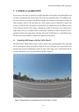
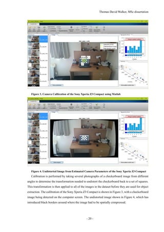
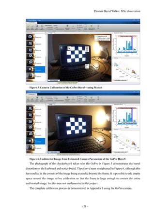
distortion to be performed.](https://image.slidesharecdn.com/52b1f858-470a-420c-adac-c44d0dbee585-161026140127/85/Dissertation-19-320.jpg)
![Thomas David Walker, MSc dissertation
- 23 -
4.1.2 Matlab
Figure 8. Image of a Globe used in the Matlab Structure from Motion Example
Figure 9. Sparse and Dense Point Clouds created in Matlab
The Structure from Motion scripts Matlab and OpenCV are both capable of calculating sparse
and dense point clouds like VisualSFM. Figure 9 shows the sparse and dense point clouds produced
by the Structure from Motion example in Matlab [26], created from five photographs of the globe in
Figure 8 from different angles, but attempting to use the same code for a large number of high reso-
lution photographs would cause the program to run out of memory. However, Matlab is less memory
efficient, so it cannot load and process as many images before the computer runs out of memory.
OpenCV can also support a dedicated graphics card to increase the processing speed, as opposed to
running the entire program on the CPU (Central Processing Unit).](https://image.slidesharecdn.com/52b1f858-470a-420c-adac-c44d0dbee585-161026140127/85/Dissertation-23-320.jpg)
![Thomas David Walker, MSc dissertation
- 24 -
4.1.3 OpenCV
The Structure from Motion libraries in OpenCV and Matlab allow for better integration of the
dynamic elements, as having access to the source code provides the ability to output the coordinates
of each camera position. OpenCV is faster and more memory efficient than Matlab, as the memory
management is much more suited for copying and editing large images. For instance, copying an
image in OpenCV does not create an exact duplicate in the memory, it simply allocates a pointer to
it, and stores the changes. Only when the output image is created is there the need to allocate the
array, and populate it with the changed and unchanged pixel values [27].
The Structure from Motion module in OpenCV requires several open source libraries that are only
supported on Linux [28], so several distributions of Linux were tested on a laptop. There is no dif-
ference in OpenCV’s compatibility between distributions of Linux, but Ubuntu 14.04 LTS was the
first one to be used due to the wide range of support available. It is also the distribution used on the
Linux computers at the University of Surrey, which have OpenCV installed on them. Due to unfa-
miliarity with the interface, a derivative of Ubuntu called Ubuntu MATE was installed in on the
laptop in its place, as the desktop environment can be configured to be very similar to Windows.
However, this version suffered from crashes that would leave the laptop completely unresponsive,
so a similar distribution called Linux Mint was used instead. Like Ubuntu MATE, it is derived from
Ubuntu and can be installed with the MATE desktop environment, although it has better support for
laptop graphics cards, which is likely to have been the cause of the crashes.
Installing OpenCV on Linux Mint was straightforward with the help of the guides provided in the
OpenCV documentation [29], however the installation of the Structure from Motion modules was
not. Despite having the required dependencies installed and ensuring that the contrib modules were
included in the compiling of OpenCV [30], the required header files for the reconstruction such as
sfm.hpp and viz.hpp were not installed in the usr/local/include/opencv2 folder. Neither man-
ually moving the header files to this folder nor changing the path that they are looked for allowed the
scripts to compile. Although the Linux computers in the University of Surrey’s CVSSP (Centre for
Vision, Speech and Signal Processing) did have OpenCV installed with the contrib modules, the
ability to develop the project outside of campus during working hours was necessary to achieve pro-
gress.
4.1.4 Photoscan
A commercial program called Agisoft Photoscan was used for the static reconstruction as it is
capable of creating a textured 3D mesh, and has significantly more options to allow for a higher
quality reconstruction. It was initially used for the duration of the free trial period of one month, but
the University generously purchased a license to have it installed on one of the Linux computers in](https://image.slidesharecdn.com/52b1f858-470a-420c-adac-c44d0dbee585-161026140127/85/Dissertation-24-320.jpg)
![Thomas David Walker, MSc dissertation
- 30 -
5 DYNAMIC RECONSTRUCTION
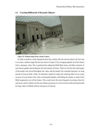
Dynamic elements in a scene, such as pedestrians, cannot easily be modelled as animated 3D objects.
This is because they cannot be seen from all sides simultaneously with a single camera, and their
shape changes with each frame. There has been success in modelling rigid objects such as vehicles
in 3D, but it is only possible because their shape remains consistent over time [18]. Approximating
a 3D model of a person from a video and mapping their movement to it is possible, but the quality
of the model and the accuracy of the animation are limited, and the implementation is beyond the
scope of this project.
The dynamic objects are implemented as animated ‘billboards’, which are 2D planes that display
an animation of the moving object. To extract these from the video, it is necessary to track objects
even when they have been partially or fully occluded, so that they can be recognised once they be-
come visible again. The billboards are created by cropping the video to a bounding box around the
moving object, but in order to remove the clutter around the object, a transparency layer is created
using background subtraction. The aim is to create a set of folders that each contain the complete
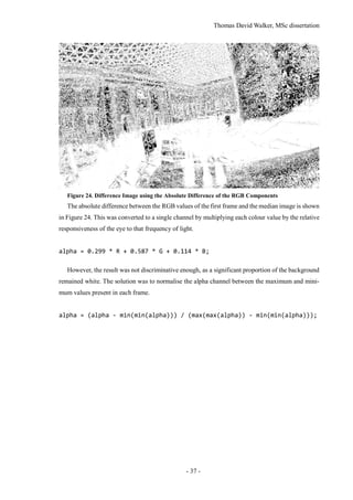
animation of a single object, which can then be imported in to Unity.
It is possible to track people from a moving camera, allowing the same video to be used for the
static and dynamic reconstructions. However, the creation of a transparency layer significantly more
challenging, as it is not possible to average the frames together to make a median image for back-
ground subtraction. The static reconstruction could be aligned with the model in each frame, but the
inaccuracy of the model prevents the background subtraction from being as effective. The quality of
the billboards would also be reduced, as they are more convincing when the billboard animation is
created from a fixed position.
One method that would allow tracking to be improved would be to perform a second pass on the
video, with the frames played in reverse. This would allow objects to be tracked before they are
visible in the video, which would improve the dynamic 3D reconstruction as it would prevent them
from suddenly appearing. This is a consideration for future work.
5.1 Tracking and Extracting Moving Objects
Two different object tracking algorithms were implemented in the project, with one specialising in
detecting people and the other used to detect any form of movement and track connected components.
The problem with using motion detection for tracking people is that it often fails to extract the entire
person, and objects that occlude each other temporarily are merged into a single component. This is
because the morphological operation for connecting regions has no information on the depth of the
scene, so it cannot easily separate two different moving objects that have any amount of overlap.](https://image.slidesharecdn.com/52b1f858-470a-420c-adac-c44d0dbee585-161026140127/85/Dissertation-30-320.jpg)
![Thomas David Walker, MSc dissertation
- 31 -
5.1.1 Detecting People
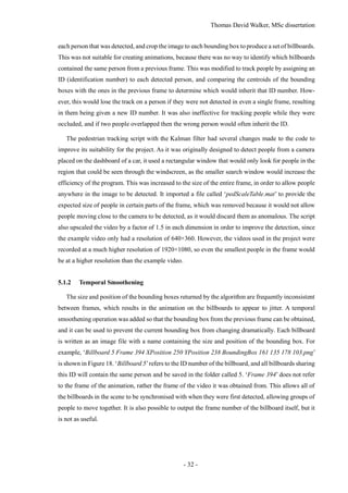
Figure 17. Multiple Pedestrians Identified and Tracked Using a Kalman Filter
The output of the Matlab script for tracking people with the Kalman filter is shown in Figure 17.
The number above each bounding box displays the confidence score of the track, which indicates the
certainty of the bounding box containing a person. This score is used to discard a tracked object if it
is below the specified threshold value.
This script is a modification of one of the examples in the Matlab documentation called ‘Tracking
Pedestrians from a Moving Car’ [15], which uses a function called detectPeopleACF() to create
bounding boxes around the people detected in each frame [31]. This utilises aggregate channel fea-
tures [32], which comprise of HOG descriptors (Histogram of Oriented Gradients) [33] and gradient
magnitude, in order to match objects to a training set while being robust to changes in illumination
and scale.
Matlab has support for two data sets for pedestrian detection called the Caltech Pedestrian Dataset
[34] and the INRIA (Institut National de Recherche en Informatique et en Automatique) Person Da-
taset [35]. Caltech uses a set of six training sets and five test sets of approximately 1 Gigabyte in size
each, while the total size of the training and test data for INRIA is only 1 Gigabyte. Caltech was also
created more recently, so it was used for this project. Both sets are only trained on people who are
standing upright, which has resulted in some people in the bottom-left corner of the Figure 17 not
being detected. Due to the lack of a tripod, the GoPro camera had to be placed on the bannister of
the stairs, which slopes downwards to the centre of the Great Hall. Therefore, it is essential that either
the camera is correctly oriented or the video is rotated in order to improve the detection of people.
The first attempt to create billboards of people with the detectPeopleACF() function simply
called it on each frame without applying any tracking. This was able to create bounding boxes around](https://image.slidesharecdn.com/52b1f858-470a-420c-adac-c44d0dbee585-161026140127/85/Dissertation-31-320.jpg)
![Thomas David Walker, MSc dissertation
- 34 -
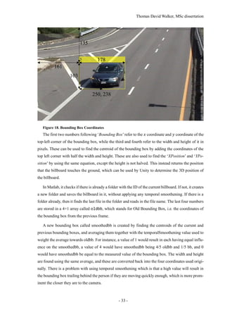
5.1.3 Detecting Moving Objects
Figure 19. Detected People Using Connected Components
In order to allow billboards to be created of any type of moving object, and not just pedestrians,
the Matlab example called ‘Motion-Based Multiple Object Tracking’ [36] was modified to export
billboards. Although it has successfully tracked several people in Figure 19, there are many more
people who have much larger bounding boxes than they require, and others who are being tracked as
multiple objects. The number above the bounding boxes indicates the ID number of the tracked ob-
ject, which can also display ‘predicted’ when it is using the estimated position provided by the
Kalman filter.
Figure 20. Alpha Mask Created Using Connected Components
The main issue of using connected components is shown in Figure 20, where two people have a
slight overlap in their connected components, resulting in them being identified as a single object.
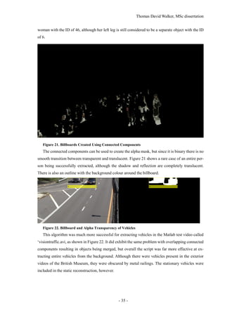
The connected component of the woman with the ID of 22 in Figure 19 has become merged with the](https://image.slidesharecdn.com/52b1f858-470a-420c-adac-c44d0dbee585-161026140127/85/Dissertation-34-320.jpg)
![Thomas David Walker, MSc dissertation
- 41 -
output QuickTime’s .mov format, which supports an alpha channel for transparency, was success-
fully integrated into the code, but the decision was made to use a sequence of .png images instead.
An advantage to using images is that the dimensions can be different for each frame.
In Unity a script was used to assign the texture of a billboard to the first image in a specific folder,
and have the index of the image updated 60 times a second [37]. There is also an option to repeat the
animation once it completes, so the scene does not become empty once all of the billboard’s anima-
tions have played once. The billboards include a timecode that indicates the frame it was taken from
in the original video, which could be used to delay the start of a billboard’s animation in order to
synchronise groups of people moving together, but this was not implemented in the project.
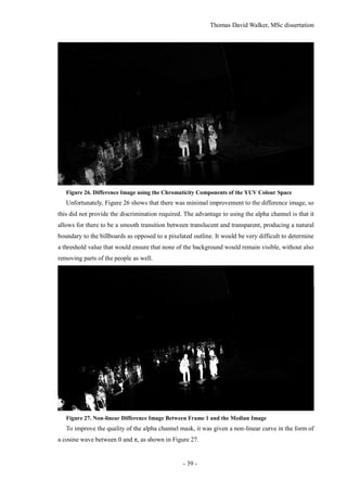
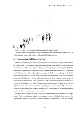
Figure 29. Comparison of Billboards with and without Perspective Correction
Once it was possible to display an animated texture in Unity, it was necessary to have the billboard
face the camera at all times in order to prevent the object from being seen from the side and appearing
two-dimensional [38]. The first script that was used would adjust the angle of the billboard each
frame in order to always be facing towards the camera, including tilting up or down when seen from
above or below. This prevented the billboard from appearing distorted, but it would also cause the
billboard to appear to float in the air or drop below the floor. By restricting the rotation to only be
along the vertical axis, the billboards would retain their correct position in 3D space. In Figure 29,
the same object is represented using two different methods for facing the camera, with the object on
the left tilting towards the viewer as it is being seen from below, while the object on the right remains
vertical. This script was modified to be able to face the main light source in the scene, which was
applied to a copy of the billboard that could not be seen by the viewer but could cast shadows. This
ensures that the shadow is always cast from the full size of the billboard, and does not become two-
dimensional if the billboard has been rotated perpendicularly to the light source. However, the
shadow does disappear if the light source is directly above the billboard.](https://image.slidesharecdn.com/52b1f858-470a-420c-adac-c44d0dbee585-161026140127/85/Dissertation-41-320.jpg)
![Thomas David Walker, MSc dissertation
- 42 -
5.4 Virtual Reality
To create the static reconstruction, a video recorded at 4K at 15 frames per second was taken while
walking around the building, while the videos used for the dynamic reconstruction were recorded at
1080p at 60 frames per second while the camera was placed on the stairs. In a virtual reality headset,
a high frame rate is necessary to improve spatial perception, reduce latency in head tracking, and
minimise motion sickness, so headsets typically operate at 60 frames per second or above [39]. Alt-
hough the frame rate of a Unity program is only limited by the processing power of the computer
and the refresh rate of the VR headset, if the object tracking was performed at a low frame rate such
as 15 frames per second, then the animation would be noticeably choppy compared to the movement
of the viewer. This would also limit the precision of the 3D position of the billboards.
It is possible to interpolate a video to a higher frame rate using motion prediction, although the
quality is dependent on how predictable the movement is. VR headsets typically operate at 90 or 120
frames per second, so it would be possible to interpolate the 60 fps footage to match the desired
frame rate. Although this could be done for the 4K 15 fps footage as well, this would only look
acceptable for simple translational movement such as a vehicle moving along a road, while the com-
plex motion of a human body walking, comprised of angular motions and self-occlusion, would
create visible artefacts [40].
Unity is a game engine that can be used to create interactive 3D environments that can be viewed
through a VR headset. The version of Unity used in this project is 5.4.0f3, which features improve-
ments in several aspects related to virtual reality [41]. This includes optimisation of the single-pass
stereo rendering setting, which allows the views for each eye to be computed more quickly and effi-
ciently, resulting in a higher frame rate, as well as providing native support for the OpenVR format
used in the headset owned by the University of Surrey.
In addition to running the virtual reality application on a computer through a VR headset, it is
also possible to compile the project for a mobile phone and view it through a headset adapter such
as Google cardboard. The model is rendered entirely with the phone, as opposed to acting as a display
for a computer. The Google cardboard use lenses to magnify each half of the phone’s screen to take
up the entire field of view, while the phone uses its accelerometers to determine the angle of the head.
Unity provides asset packages that allow controllable characters or visual effects to be added to
the project. These take the form of prefabs, which are templates for game objects as well as compo-
nents that can be attached to game objects. Virtual reality is typically experienced through the
viewpoint of the character, and two of the controllable character prefabs allow for the scene to be
explored with this perspective. These are the FPSController.prefab and RigidBodyFPSControl-
ler.prefab game objects. Rigid Body is a component in Unity that allows a game object to be treated
as a physics object, so it moves with more realistic momentum at the expense of responsiveness. This](https://image.slidesharecdn.com/52b1f858-470a-420c-adac-c44d0dbee585-161026140127/85/Dissertation-42-320.jpg)

![Thomas David Walker, MSc dissertation
- 46 -
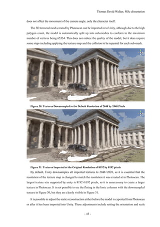
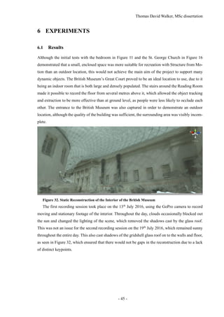
Figure 33. Static Reconstruction of the Exterior of the British Museum
This was also beneficial for recording the exterior of the British Museum, as clouds have been
shown to interfere with the modelling of buildings in the previous experiment with the St. George
Church. As it shared similar architecture with the British Museum, particularly with the use of col-
umns, it was necessary to capture footage from the other side of the columns to ensure that they were
complete in the reconstruction. As Figure 33 demonstrates, the columns are separate from the build-
ing, allowing the main entrance to be seen between them.
6.2 Discussion of results
The initial model of the Great Court highlighted an issue with Structure from Motion, which is loop
closure [42]. Due to the rotational symmetry of the interior, photographs from the opposite sides of
the building were being incorrectly matched, resulting in a model that was missing one half. There
is a technique called ‘similarity averaging’ that creates correspondences between images simultane-
ously as opposed to incrementally in bundle adjustment [43].](https://image.slidesharecdn.com/52b1f858-470a-420c-adac-c44d0dbee585-161026140127/85/Dissertation-46-320.jpg)

![Thomas David Walker, MSc dissertation
- 49 -
8 REFERENCES
[1] BBC, “Click goes 360 in world first,” BBC, 23 February 2016. [Online]. Available:
http://www.bbc.co.uk/mediacentre/worldnews/2016/click-goes-360-in-world-first.
[Accessed 18 August 2016].
[2] C. Mei and P. Rives, “Single View Point Omnidirectional Camera Calibration from
Planar Grids,” INRIA, Valbonne, 2004.
[3] D. G. Lowe, “Distinctive Image Features from Scale-Invariant Keypoints,”
International Journal of Computer Vision, 5 January 2004.
[4] S. Perreault and P. Hébert, “Median Filtering in Constant Time,” IEEE
TRANSACTIONS ON IMAGE PROCESSING, vol. 16, no. 7, September 2007.
[5] J. Civera, A. J. Davison and J. M. M. Montiel, “Structure from Motion Using the
Extended Kalman Filter,” Springer Tracts in Advanced Robotics, vol. 75, 2012.
[6] M. A. Magnor, O. Grau, O. Sorkine-Hornung and C. Theobalt, Digital Representations
of the Real World, Boca Raton: Taylor & Francis Group, LLC, 2015.
[7] R. Szeliski, Computer Vision: Algorithms and Applications, Springer, 2010, pp. 343-
380.
[8] Microsoft, “Photosynth Blog,” Microsoft, 10 July 2015. [Online]. Available:
https://blogs.msdn.microsoft.com/photosynth/. [Accessed 29 April 2016].
[9] S. Agarwal, N. Snavely, I. Simon, S. M. Seitz and R. Szeliski, “Building Rome in a
Day,” in International Conference on Computer Vision, Kyoto, 2009.
[10] R. A. Newcombe, S. J. Lovegrove and A. J. Davison, “DTAM: Dense Tracking and
Mapping in Real-Time,” Imperial College, London, 2011.
[11] R. Newcombe, “Dense Visual SLAM: Greedy Algorithms,” in Field Robotics Centre,
Pittsburgh, 2014.
[12] K. Lebeda, S. Hadfield and R. Bowden, “Texture-Independent Long-Term Tracking
Using Virtual Corners,” IEEE Transactions on Image Processing, 2015.
[13] K. Lebeda, S. Hadfield and R. Bowden, “2D Or Not 2D: Bridging the Gap Between
Tracking and Structure from Motion,” Guildford, 2015.
[14] A. Shaukat, A. Gilbert, D. Windridge and R. Bowden, “Meeting in the Middle: A Top-
down and Bottom-up Approach to Detect Pedestrians,” in 21st International Conference
on Pattern Recognition, Tsukuba, 2012.
[15] MathWorks, “Tracking Pedestrians from a Moving Car,” MathWorks, 2014. [Online].](https://image.slidesharecdn.com/52b1f858-470a-420c-adac-c44d0dbee585-161026140127/85/Dissertation-49-320.jpg)
![Thomas David Walker, MSc dissertation
- 50 -
Available: http://uk.mathworks.com/help/vision/examples/tracking-pedestrians-from-a-
moving-car.html. [Accessed 12 March 2016].
[16] L. Zappellaa, A. D. Bueb, X. Lladóc and J. Salvic, “Joint Estimation of Segmentation
and Structure from Motion,” Computer Vision and Image Understanding, vol. 117, no. 2,
pp. 113-129, 2013.
[17] K. Lebeda, S. Hadfield and R. Bowden, “Exploring Causal Relationships in Visual
Object Tracking,” in International Conference on Computer Vision, Santiago, 2015.
[18] K. Lebeda, S. Hadfield and R. Bowden, “Dense Rigid Reconstruction from
Unstructured Discontinuous Video,” in 3D Representation and Recognition, Santiago,
2015.
[19] K. Lebeda, J. Matas and R. Bowden, “Tracking the Untrackable: How to Track When
Your Object Is Featureless,” in ACCV 2012 Workshops, Berlin, 2013.
[20] P. Halarnkar, S. Shah, H. Shah, H. Shah and A. Shah, “A Review on Virtual Reality,”
International Journal of Computer Science Issues, vol. 9, no. 6, pp. 325-330, November
2012.
[21] V. Kamde, R. Patel and P. K. Singh, “A Review on Virtual Reality and its Impact on
Mankind,” International Journal for Research in Computer Science, vol. 2, no. 3, pp. 30-
34, March 2016.
[22] H. S. Malvar, L.-w. He and R. Cutler, “High-Quality Linear Interpolation for
Demosaicing of Bayer-Patterned Color Images,” Microsoft Research, Redmond, 2004.
[23] D. Khashabi, S. Nowozin, J. Jancsary and A. Fitzgibbon, “Joint Demosaicing and
Denoising via Learned Non-parametric Random Fields,” Microsoft Research, Redmond,
2014.
[24] GoPro, “Hero3+ Black Edition User Manual,” 28 October 2013. [Online]. Available:
http://cbcdn1.gp-
static.com/uploads/product_manual/file/202/HERO3_Plus_Black_UM_ENG_REVD.pdf
. [Accessed 20 February 2016].
[25] Sony, “Xperia™ Z3 Compact Specifications,” Sony, September 2014. [Online].
Available: http://www.sonymobile.com/global-en/products/phones/xperia-z3-
compact/specifications/. [Accessed 22 February 2016].
[26] MathWorks, “Structure From Motion From Multiple Views,” MathWorks, 21 August
2016. [Online]. Available: http://uk.mathworks.com/help/vision/examples/structure-from-
motion-from-multiple-views.html. [Accessed 21 August 2016].
[27] OpenCV Development Team, “OpenCV API Reference,” Itseez, 12 August 2016.](https://image.slidesharecdn.com/52b1f858-470a-420c-adac-c44d0dbee585-161026140127/85/Dissertation-50-320.jpg)
![Thomas David Walker, MSc dissertation
- 51 -
[Online]. Available: http://docs.opencv.org/2.4/modules/core/doc/intro.html. [Accessed
12 August 2016].
[28] OpenCV, “SFM module installation,” itseez, 28 February 2016. [Online]. Available:
http://docs.opencv.org/trunk/db/db8/tutorial_sfm_installation.html. [Accessed 28
February 2016].
[29] OpenCV Tutorials, “Installation in Linux,” itseez, 21 August 2016. [Online]. Available:
http://docs.opencv.org/2.4/doc/tutorials/introduction/linux_install/linux_install.html#linu
x-installation. [Accessed 21 August 2016].
[30] OpenCV, “Build opencv_contrib with dnn module,” itseez, 21 August 2016. [Online].
Available: http://docs.opencv.org/trunk/de/d25/tutorial_dnn_build.html. [Accessed 21
August 2016].
[31] MathWorks, “Detect people using aggregate channel features (ACF),” MathWorks,
2014. [Online]. Available: http://uk.mathworks.com/help/vision/ref/detectpeopleacf.html.
[Accessed 24 August 2016].
[32] B. Yang, J. Yan, Z. Lei and S. Z. Li, “Aggregate Channel Features for Multi-view Face
Detection,” in International Joint Conference on Biometrics, Beijing, 2014.
[33] N. Dalal and B. Triggs, “Histograms of Oriented Gradients for Human Detection,”
CVPR, Montbonnot-Saint-Martin, 2005.
[34] P. Dollár, “Caltech Pedestrian Detection Benchmark,” Caltech, 26 July 2016. [Online].
Available: http://www.vision.caltech.edu/Image_Datasets/CaltechPedestrians/. [Accessed
28 August 2016].
[35] N. Dalal, “INRIA Person Dataset,” 17 July 2006. [Online]. Available:
http://pascal.inrialpes.fr/data/human/. [Accessed 28 August 2016].
[36] MathWorks, “Motion-Based Multiple Object Tracking,” MathWorks, 2014. [Online].
Available: http://uk.mathworks.com/help/vision/examples/motion-based-multiple-object-
tracking.html. [Accessed 24 August 2016].
[37] arky25, “Unity Answers,” 30 August 2016. [Online]. Available:
http://answers.unity3d.com/questions/55607/any-possibility-to-play-a-video-in-unity-
free.html. [Accessed 30 August 2016].
[38] N. Carter and H. Scott-Baron, “CameraFacingBillboard,” 30 August 2016. [Online].
Available: http://wiki.unity3d.com/index.php?title=CameraFacingBillboard. [Accessed
30 August 2016].
[39] D. J. Zielinski, H. M. Rao, M. A. Sommer and R. Kopper, “Exploring the Effects of
Image Persistence in Low Frame Rate Virtual Environments,” IEEE VR, Los Angeles,](https://image.slidesharecdn.com/52b1f858-470a-420c-adac-c44d0dbee585-161026140127/85/Dissertation-51-320.jpg)
![Thomas David Walker, MSc dissertation
- 52 -
2015.
[40] D. D. Vatolin, K. Simonyan, S. Grishin and K. Simonyan, “AviSynth MSU Frame Rate
Conversion Filter,” MSU Graphics & Media Lab (Video Group), 10 March 2011. [Online].
Available: http://www.compression.ru/video/frame_rate_conversion/index_en_msu.html.
[Accessed 5 August 2016].
[41] Unity, “Unity - What's new in Unity 5.4,” Unity, 28 July 2016. [Online]. Available:
https://unity3d.com/unity/whats-new/unity-5.4.0. [Accessed 9 August 2016].
[42] D. Scaramuzza, F. Fraundorfer, M. Pollefeys and R. Siegwart, “Closing the Loop in
Appearance-Guided Structure-from-Motion for Omnidirectional Cameras,” HAL,
Marseille, 2008.
[43] Z. Cui and P. Tan, “Global Structure-from-Motion by Similarity Averaging,” in IEEE
International Conference on Computer Vision (ICCV), Burnaby, 2015.
[44] Unity, “Unity - Manual: Camera Motion Blur,” Unity, 28 July 2016. [Online].
Available: https://docs.unity3d.com/Manual/script-CameraMotionBlur.html. [Accessed 9
August 2016].](https://image.slidesharecdn.com/52b1f858-470a-420c-adac-c44d0dbee585-161026140127/85/Dissertation-52-320.jpg)
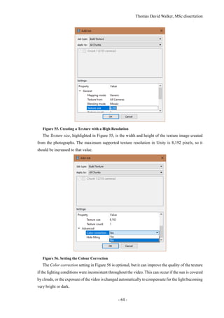


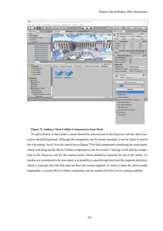
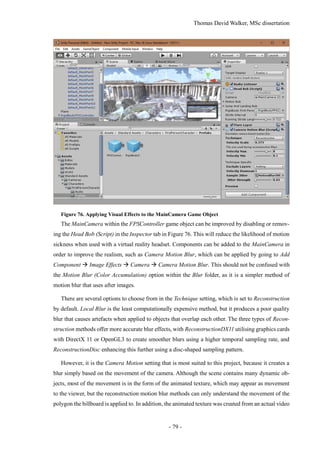
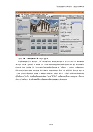
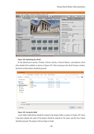
![Thomas David Walker, MSc dissertation
- 80 -
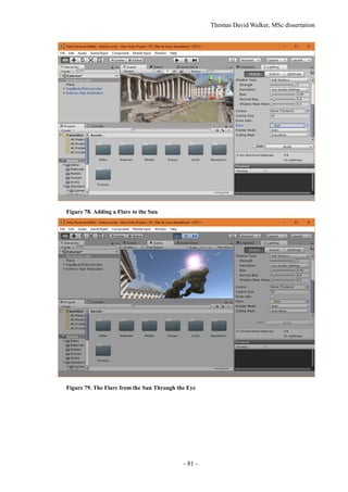
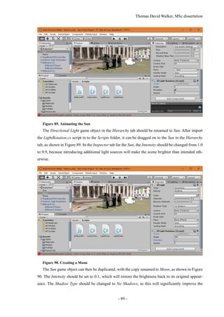
recording, which inherently contains motion blur, so there is no need to apply it to the polygon. Also,
by calculating motion blur just for the camera and not for each object, there is less impact on perfor-
mance, which is essential for achieving the high frame rate needed to virtual reality. Further
information on the motion blur settings can be found in the Unity documentation [44].
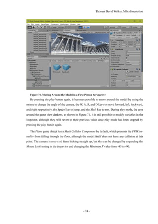
Figure 77. Lighting the Scene
The lighting of the scene can be configured by selecting Window Lighting, which will bring
up the Lighting tab in a separate window. This can be snapped in to the editor window next to the
Inspector tab as shown in Figure 77. In the Environment Lighting section, the Sun will be set to None
(Light) by default, although Unity will automatically select the light source with the greatest intensity
if there is no light source selected. This can be specified as the Directional Light in case additional
light sources are introduced, such as a moon.
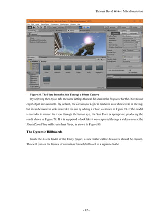
If the lighting of the scene is considered too bright, the Ambient Intensity can be reduced to 0, as
this removes the light reflected from the skybox. This results in the textures looking much closer to
the model that was exported from Photoscan. However, this does prevent the colour of the scene
from changing if a day and night cycle is implemented.](https://image.slidesharecdn.com/52b1f858-470a-420c-adac-c44d0dbee585-161026140127/85/Dissertation-80-320.jpg)