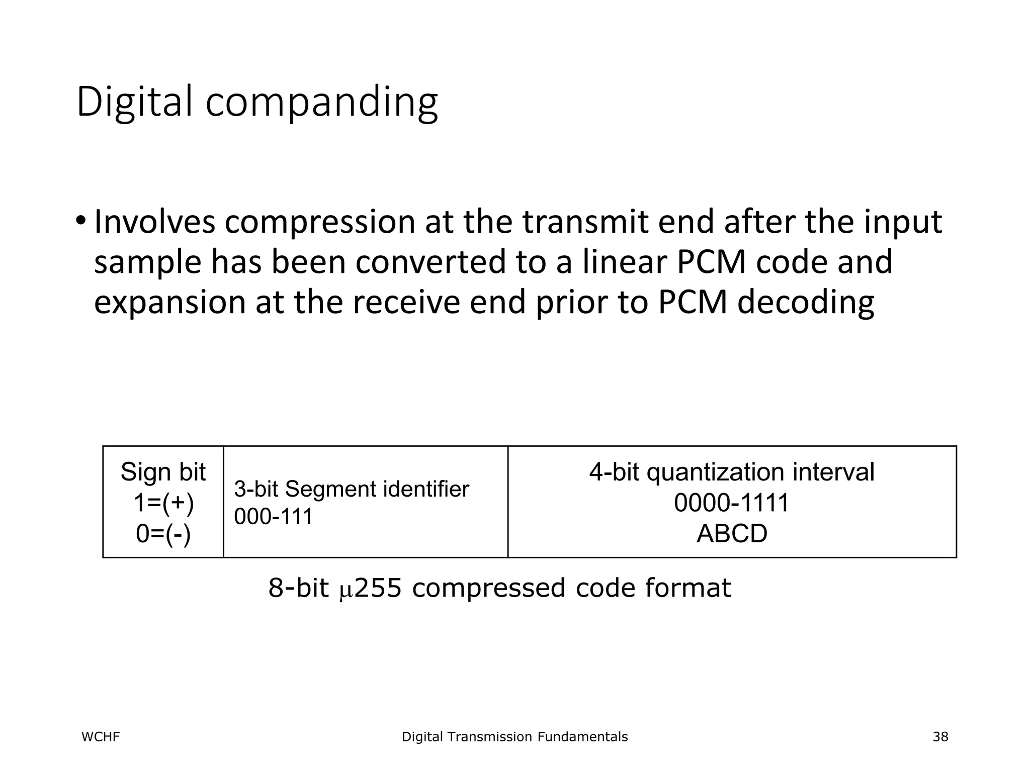
DIGITAL
TRANSMISSION
How Digital Signals Are Transmitted from the Source to Destination
1
MSU, MARAWI CITY
EEE DEPARTMENT
Introduction
• Digital transmission is the transmittal of digital pulses between two
points in a communications system.
• The original source information may already be in digital form or it
may be analog signals that must be converted to digital pulses prior
to transmission and converted back to analog form at the receive
end.
Digital Transmission Fundamentals 2
Advantages of Digital Transmission
• Noise immunity.
• Less susceptible to undesired amplitude, frequency, and phase variations.
• Digital technology
• Low cost LSI/VLSI technology
• Data integrity
• Longer distances over lower quality lines
• Capacity utilization
• High bandwidth links economical
• High degree of multiplexing easier with digital techniques
• Security & Privacy
• Encryption
• Integration
• Can treat analog and digital data similarly
Digital Transmission Fundamentals 3
Disadvantages of digital transmission
• More bandwidth used.
• Needs conversion.
• Requires precise time synchronization.
• Incompatible with existing analog facilities.
Digital Transmission Fundamentals 4
Pulse Modulation
• Pulse modulation includes many different methods of converting
information into pulse form for transferring pulses from a source to
destination.
• The four predominant methods of pulse modulation:
• Pulse Width Modulation (PWM)
• Pulse Position Modulation (PPM)
• Pulse Amplitude Modulation (PAM)
• Pulse Code Modulation (PCM)
Digital Transmission Fundamentals 5
Starts with Sampling
WCHF Digital Transmission Fundamentals 6
Volts
time
Pulse amplitude modulation
WCHF Digital Transmission Fundamentals 7
Volts
time
PDM (or PWM)
WCHF Digital Transmission Fundamentals 8
Volts
time
max = largest Positive
min = largest Negative
time
Pulse Duration Modulation (Pulse Width Modulation)
PPM
WCHF Digital Transmission Fundamentals 9
Volts
time
max = largest Positive
min = largest Negative
time
Pulse Position Modulation
PCM
WCHF Digital Transmission Fundamentals 10
Volts
time
time
01000 01000
8 8
-2
-9
-1
5
-7
10010 11001 10001 00101 10111
Pulse Code Modulation
Pulse code modulation
A true digital pulse modulation
11
Pulse Code Modulation
• The pulse of fixed length and amplitude
• It is a binary system; a pulse or lack of pulse within a prescribed time
slot represents either a logic 1 or 0 condition
WCHF Digital Transmission Fundamentals 12
Simplified PCM Block diagram
WCHF Digital Transmission Fundamentals 13
Analog
Input
Band
pass
filter
Sample
and
Hold
Analog-to-
digital
converter
Digital-to-
analog
converter
Hold Circuit
Low
Pass
Filter
Analog
Output
PAM
PAM
Transmission medium
Procedures in pcm
• Sampling
• Quantizing
• assigning PCM codes to absolute magnitudes
• Coding
WCHF Digital Transmission Fundamentals 14
Sample-and-Hold CIrcuit
• Its purpose is to sample periodically the continually changing analog
input signal and convert the samples to a series of constant amplitude
PAM levels
WCHF Digital Transmission Fundamentals 15
Analog
input
Sampling pulse
PAM output
Sample-and-Hold circuit
C1
Q1
Z2
Z1
Types of Sampling
• Flat-top sampling – the sample voltage is held at a constant
amplitude during the A/D conversion time; this is done by
sampling the analog signal for a short period of time
• Natural sampling – the sample time is made longer and the
analog-to-digital conversion takes place with changing analog
signal. This introduces more aperture distortion and requires a
faster A/D converter
WCHF Digital Transmission Fundamentals 16
Natural sampling
 In natural sampling,
the sampling waveform
S(t) consists of a train
of pulses having
duration  and
separated by sampling
time Ts.
WCHF Digital Transmission Fundamentals 17
Flat-top sampling
WCHF Digital Transmission Fundamentals 18
 PAM pulses generated from natural sampling are not frequently used.
 Instead, flat-topped pulses are customarily used because flat-top
sampling facilitates the design of the electronic circuitry to perform
sampling.
Sampling rate (fs)
• Nyquist Rate - the minimum rate at which a signal can be sampled
without introducing errors, which is twice the highest frequency
present in the signal.
• For a sample to be reproduced accurately at the receiver, each cycle
of the analog signal (fa) must be sampled at least twice.
• If fs is less than two times fa, distortion will result. This distortion is
called aliasing or foldover distortion.
WCHF Digital Transmission Fundamentals 19
a
s f
f 2

Aliasing
WCHF Digital Transmission Fundamentals 20
3fs
fs
Audio
0 fa 2fs
fs - fa 2fs - fa
3fs - fa
3fs + fa
Audio
0 fa 2fs 3fs
fs
fs - fa 2fs - fa
3fs - fa
3fs + fa
Shaded areas indicate
spectral foldover
No aliasing
Aliasing distortion
Aliasing
Ex. For a PCM system with a maximum input frequency of 4 kHz, determine the
minimum sample rate and the alias frequency produced if a 5 kHz audio signal
were allowed to enter the sample and hold circuit.
Solution : Nyquist sampling theorem: fs >fa, therefore:
fs = 8 kHz.
Produces an alias frequency of 3 kHz. see Figure
WCHF Digital Transmission Fundamentals 21
Folded binary code
Sign Magnitude Decimal
1 1 1 +3
1 1 0 +2
1 0 1 +1
1 0 0 +0
0 0 0 -0
0 0 1 -1
0 1 0 -2
0 1 1 -3
WCHF Digital Transmission Fundamentals 22
Overload distortion
• Overload distortion (peak limiting) results if the magnitude of the
sample exceeds the highest quantization interval
WCHF Digital Transmission Fundamentals 23
resolution
• Magnitude of the minimum step size.
• Equal to the voltage of the least significant bit.
• The minimum voltage other than 0 V (zero) that can be decoded by
the DAC at the receiver.
• The smaller the magnitude of the minimum step size the better the
resolution and the more accurately the quantization interval will
resemble the actual analog sample.
WCHF Digital Transmission Fundamentals 24
Quantization error
• An error which results from rounding the magnitude of the sample to
the nearest valid code
•the maximum amplitude is one-half the
resolution
WCHF Digital Transmission Fundamentals 25
Dynamic range
• Dynamic Range (DR) is the ratio of the largest possible magnitude to
the smallest possible magnitude that can be decoded by the DAC
(Digital-to-Analog Converter)
• The number of bits used for a PCM code is
WCHF Digital Transmission Fundamentals 26
resolution
V
DR max

1
2 
 DR
n
Coding efficiency
Including the sign bit
WCHF Digital Transmission Fundamentals 27
%
100
.
min
x
bits
of
number
actual
bits
of
no
imum
efficiency
Coding 
Signal-to-quantization Noise ratio
• For linear PCM code
• v = rms signal voltage
• q = quantization interval
WCHF Digital Transmission Fundamentals 28
q
v
dB
SQR log
20
8
.
10
)
( 

Linear vs nonlinear PCM Code
• Linear codes – the magnitude change between any two
successive steps is uniform
• The accuracy for the higher-amplitude analog
signals is the same as for the lower-amplitude
signals
• The SQR for the lower-amplitude signals is less
than for the higher-amplitude signals
• Nonlinear codes – the step size increases with the amplitude of
the input signal
• There are more codes for the lower-amplitudes
than for higher-amplitudes (for voice
transmission)
WCHF Digital Transmission Fundamentals 29
Idle channel noise
• During times when there is no analog input signal, the only input to
the PAM sampler is random, thermal noise. This noise is called idle
channel noise and is converted to a PAM sample just as if it were a
signal.
WCHF Digital Transmission Fundamentals 30
Types of quantization
• Midthread quantization – the first quantization interval is made
larger in amplitude than the rest of the steps
• It is a method to reduce idle channel noise
• Midrise quantization – the lowest-magnitude positive and
negative codes have the same voltage range as all the other
codes
WCHF Digital Transmission Fundamentals 31
Types of quantization
WCHF Digital Transmission Fundamentals 32
Coding methods
1. Level-at-a-time coding
• This type of coding compares the PAM signal to a ramp
waveform while a binary counter is being advanced at a uniform
rate
• When the ramp waveform equals or exceeds the PAM sample,
the counter contains the PCM code
• Requires that 2n sequential decisions be made for each PCM
code generated
• Generally limited to low-speed applications
2. Digit-at-a-time coding
• This type of coding determines each digit of the PCM code
sequentially, it uses a reference weight or code to determine the
PCM code
3. Word-at-a-time coding
• Word-at-a-time coders are flash encoders and more complex;
they are more suitable for high-speed applications
WCHF Digital Transmission Fundamentals 33
companding
• Is the process of compressing, then expanding
• The higher amplitude analog signals are compressed prior to
transmission, then expanded at the receiver
• Analog
• -Law companding (US and Japan)
• A-law companding (Europe)
• Digital
WCHF Digital Transmission Fundamentals 34
-Law companding
• Vmax = max. uncompressed analog input amplitude
• Vin = amplitude of the input signal at a particular instant of time
•  = parameter used to defined the amount of compression
• Vout = compressed output amplitude
WCHF Digital Transmission Fundamentals 35
 








 

1
ln
1
ln
max
max V
V
x
V
V
in
out
Example: For a compressor with a µ= 255, det
a)Voltage gain for Vin: Vmax, 0.75Vmax, 0.5Vmax, 0.25Vmax
b)The compressed output voltage for Vmax = 4 V.
c)Input and output dynamic ranges and compression.
WCHF Digital Transmission Fundamentals 36
A-law companding
WCHF Digital Transmission Fundamentals 37
A
V
V
A
V
V
A
V
V in
in
out
1
0
ln
1 max
max
max 



1
1
ln
1
)
ln(
1
max
max
max 




V
V
A
A
V
V
A
V
V in
in
out
Digital companding
• Involves compression at the transmit end after the input
sample has been converted to a linear PCM code and
expansion at the receive end prior to PCM decoding
Sign bit
1=(+)
0=(-)
3-bit Segment identifier
000-111
4-bit quantization interval
0000-1111
ABCD
WCHF Digital Transmission Fundamentals 38
8-bit 255 compressed code format
Digital companding
Segment 12-bit linear code
8-bit compressed
code
8-bit compressed
code
12-bit recovered
code
Segment
0 S0000000ABCD S000ABCD S000ABCD S0000000ABCD 0
1 S0000001ABCD S001ABCD S001ABCD S0000001ABCD 1
2 S000001ABCDx S010ABCD S010ABCD S000001ABCD1 2
3 S00001ABCDxx S011ABCD S011ABCD S00001ABCD10 3
4 S0001ABCDxxx S100ABCD S100ABCD S0001ABCD100 4
5 S001ABCDxxxx S101ABCD S101ABCD S001ABCD1000 5
6 S01ABCDxxxxx S110ABCD S110ABCD S01ABCD10000 6
7 S1ABCDxxxxxx S111ABCD S111ABCD S1ABCD100000 7
WCHF Digital Transmission Fundamentals 39
255 encoding/decoding table
Digital companding algorithm
1. The analog signal is sampled and converted to a
linear 12-bit sign-magnitude code.
2. The sign bit is transferred directly to the 8-bit code.
3. The segment is determined by counting the number
of leading zeroes in the 11-bit magnitude portion of
the code beginning with the MSB. Subtract the
number of leading 0’s from 7. The result is the
segment number, which is converted to a 3-bit
binary number.
4. The four magnitude bits (A,B,C,D) are the
quantization interval which are substituted into the
least significant 4 bits of the 8-bit compressed code.
WCHF Digital Transmission Fundamentals 40
Example
• Determne the 12-bit code, the 8-bit compressed code, the
decoded 12-bit code, the quantization error, and the
compression error for the resolution of 0.01 V and analog
sample voltage of a) +0.05 3V, (b) -0.318 V, and ©
+10.234V.
WCHF Digital Transmission Fundamentals 41
Percentage error
WCHF Digital Transmission Fundamentals 42
100
)
(
)
(
)
(
% x
voltage
Rx
voltage
Rx
voltage
Tx
error


vocoders
• Used when digitizing speech signals only
• Used primarily in limited bandwidth applications
• Generally used for recorded information such as “wrong number”
messages, encrypted voice for transmission over analog telephone
circuits, computer output signals and educational games
WCHF Digital Transmission Fundamentals 43
Vocoding techniques
• Channel vocoders
• Formant vocoders
• Linear predictive vocoders
WCHF Digital Transmission Fundamentals 44
Vocoding techniques
• Channel vocoders
• The first channel vocoder was developed by Homer Dudley in
1928. Dudley’s vocoder compressed conventional speech
waveforms into an analog signal with a total bandwidth of
approximately 300 Hz.
• Used bandpass filters to separate the speech waveform into
narrower subbands. Each sub-band is full-wave rectified,
filtered, then digitally encoded.
• Operate at 2400 bps
• Formant vocoders
• Linear predictive vocoders
WCHF Digital Transmission Fundamentals 45
Vocoding techniques
• Channel vocoders
• Formant vocoders
• Simply determines the location of the formants and encodes and transmit
only the information with the most significant short-term components.
• Formants – three or more peak frequencies at which the spectral power of
most speech energy concentrate
• Operate at less than 100 bps
• Linear predictive vocoders
WCHF Digital Transmission Fundamentals 46
Vocoding techniques
• Channel vocoders
• Formant vocoders
• Linear predictive vocoders
• Extracts the most significant portions of speech information directly from
the time waveform rather than from the frequency spectrum as with the
channel and formant vocoders
• Typically transmit and encode speech at between 1.2 and 2.4 kbps
WCHF Digital Transmission Fundamentals 47
Delta Modulation PCM
• Uses a single-bit PCM code to achieve digital transmission of analog
signals
• If the current sample is smaller than the previous sample, a logic 0 is
transmitted
• If the current sample is larger than the previous sample, a logic 1 is
transmitted
WCHF Digital Transmission Fundamentals 48
Delta modulation
WCHF Digital Transmission Fundamentals 49
Problems with delta modulation
 Slope overload noise occurs
when the step size ∆ is too small
for the accumulator output to
follow quick changes in the input
waveform.
WCHF Digital Transmission Fundamentals 50
Original
Signal
Reconstructed
Signal
Granular
Noise
Analog
input
DAC
output
Slope overload
distortion  Granular noise occurs for any step size,
but is smaller for a small step size.
 If ∆ is decreased, the granular noise will
decrease, however the slope overload noise
will increase.
 Thus there should be an optimum value
for the step size ∆.
Adaptive Delta Modulation
• Is a delta modulation system where the step size of the DAC is
automatically varied depending on the amplitude characteristics of
the analog input signal
• This is used to reduced the effect of slope overload distortion
WCHF Digital Transmission Fundamentals 51
Differential PCM
• The difference in the amplitude of two successive samples is
transmitted rather than the actual sample
• This is to reduce the number of bits used for transmission
WCHF Digital Transmission Fundamentals 52
Pulse Transmission
53
Intersymbol interference (ISI)
• Causes of intersymbol interference
• Timing inaccuracies
• Insufficient bandwidth
• Amplitude distortion
• Phase distortion
WCHF Digital Transmission Fundamentals 54
Eye pattern
• Is a convenient technique for determining the effects of the
degradations introduced into the pulses as they travel to the
regenerator
WCHF Digital Transmission Fundamentals 55
H
h
log
20
ISI degradation =
Where H = ideal vertical opening
. h = degraded vertical opening
Eye diagram
• Eye diagram or eye pattern is a display
wherein all waveform combinations are
superimposed over adjacent signaling
intervals.
 Ideal decision times
• the horizontal lines, separated by the
signaling interval, T.
 Crosshairs
• represent the decision levels for the
regenerator
• vertical hairs - decision time
• horizontal hairs - decision level
WCHF Digital Transmission Fundamentals 56
 Data transition jitter – impairment where
the overlapping signal pattern does not
cross the horizontal zero line at exact
integer multiples of the symbol clock
Eye diagram measurement setup
MSU EEE DEPARTMENT Digital Transmission Fundamentals 57
Oscilloscope
V input H
Band limited
channel
Digital
Source
Symbol
Clock

Digital Transmission 1.ppt

  • 1.
    DIGITAL TRANSMISSION How Digital SignalsAre Transmitted from the Source to Destination 1 MSU, MARAWI CITY EEE DEPARTMENT
  • 2.
    Introduction • Digital transmissionis the transmittal of digital pulses between two points in a communications system. • The original source information may already be in digital form or it may be analog signals that must be converted to digital pulses prior to transmission and converted back to analog form at the receive end. Digital Transmission Fundamentals 2
  • 3.
    Advantages of DigitalTransmission • Noise immunity. • Less susceptible to undesired amplitude, frequency, and phase variations. • Digital technology • Low cost LSI/VLSI technology • Data integrity • Longer distances over lower quality lines • Capacity utilization • High bandwidth links economical • High degree of multiplexing easier with digital techniques • Security & Privacy • Encryption • Integration • Can treat analog and digital data similarly Digital Transmission Fundamentals 3
  • 4.
    Disadvantages of digitaltransmission • More bandwidth used. • Needs conversion. • Requires precise time synchronization. • Incompatible with existing analog facilities. Digital Transmission Fundamentals 4
  • 5.
    Pulse Modulation • Pulsemodulation includes many different methods of converting information into pulse form for transferring pulses from a source to destination. • The four predominant methods of pulse modulation: • Pulse Width Modulation (PWM) • Pulse Position Modulation (PPM) • Pulse Amplitude Modulation (PAM) • Pulse Code Modulation (PCM) Digital Transmission Fundamentals 5
  • 6.
    Starts with Sampling WCHFDigital Transmission Fundamentals 6 Volts time
  • 7.
    Pulse amplitude modulation WCHFDigital Transmission Fundamentals 7 Volts time
  • 8.
    PDM (or PWM) WCHFDigital Transmission Fundamentals 8 Volts time max = largest Positive min = largest Negative time Pulse Duration Modulation (Pulse Width Modulation)
  • 9.
    PPM WCHF Digital TransmissionFundamentals 9 Volts time max = largest Positive min = largest Negative time Pulse Position Modulation
  • 10.
    PCM WCHF Digital TransmissionFundamentals 10 Volts time time 01000 01000 8 8 -2 -9 -1 5 -7 10010 11001 10001 00101 10111 Pulse Code Modulation
  • 11.
    Pulse code modulation Atrue digital pulse modulation 11
  • 12.
    Pulse Code Modulation •The pulse of fixed length and amplitude • It is a binary system; a pulse or lack of pulse within a prescribed time slot represents either a logic 1 or 0 condition WCHF Digital Transmission Fundamentals 12
  • 13.
    Simplified PCM Blockdiagram WCHF Digital Transmission Fundamentals 13 Analog Input Band pass filter Sample and Hold Analog-to- digital converter Digital-to- analog converter Hold Circuit Low Pass Filter Analog Output PAM PAM Transmission medium
  • 14.
    Procedures in pcm •Sampling • Quantizing • assigning PCM codes to absolute magnitudes • Coding WCHF Digital Transmission Fundamentals 14
  • 15.
    Sample-and-Hold CIrcuit • Itspurpose is to sample periodically the continually changing analog input signal and convert the samples to a series of constant amplitude PAM levels WCHF Digital Transmission Fundamentals 15 Analog input Sampling pulse PAM output Sample-and-Hold circuit C1 Q1 Z2 Z1
  • 16.
    Types of Sampling •Flat-top sampling – the sample voltage is held at a constant amplitude during the A/D conversion time; this is done by sampling the analog signal for a short period of time • Natural sampling – the sample time is made longer and the analog-to-digital conversion takes place with changing analog signal. This introduces more aperture distortion and requires a faster A/D converter WCHF Digital Transmission Fundamentals 16
  • 17.
    Natural sampling  Innatural sampling, the sampling waveform S(t) consists of a train of pulses having duration  and separated by sampling time Ts. WCHF Digital Transmission Fundamentals 17
  • 18.
    Flat-top sampling WCHF DigitalTransmission Fundamentals 18  PAM pulses generated from natural sampling are not frequently used.  Instead, flat-topped pulses are customarily used because flat-top sampling facilitates the design of the electronic circuitry to perform sampling.
  • 19.
    Sampling rate (fs) •Nyquist Rate - the minimum rate at which a signal can be sampled without introducing errors, which is twice the highest frequency present in the signal. • For a sample to be reproduced accurately at the receiver, each cycle of the analog signal (fa) must be sampled at least twice. • If fs is less than two times fa, distortion will result. This distortion is called aliasing or foldover distortion. WCHF Digital Transmission Fundamentals 19 a s f f 2 
  • 20.
    Aliasing WCHF Digital TransmissionFundamentals 20 3fs fs Audio 0 fa 2fs fs - fa 2fs - fa 3fs - fa 3fs + fa Audio 0 fa 2fs 3fs fs fs - fa 2fs - fa 3fs - fa 3fs + fa Shaded areas indicate spectral foldover No aliasing Aliasing distortion
  • 21.
    Aliasing Ex. For aPCM system with a maximum input frequency of 4 kHz, determine the minimum sample rate and the alias frequency produced if a 5 kHz audio signal were allowed to enter the sample and hold circuit. Solution : Nyquist sampling theorem: fs >fa, therefore: fs = 8 kHz. Produces an alias frequency of 3 kHz. see Figure WCHF Digital Transmission Fundamentals 21
  • 22.
    Folded binary code SignMagnitude Decimal 1 1 1 +3 1 1 0 +2 1 0 1 +1 1 0 0 +0 0 0 0 -0 0 0 1 -1 0 1 0 -2 0 1 1 -3 WCHF Digital Transmission Fundamentals 22
  • 23.
    Overload distortion • Overloaddistortion (peak limiting) results if the magnitude of the sample exceeds the highest quantization interval WCHF Digital Transmission Fundamentals 23
  • 24.
    resolution • Magnitude ofthe minimum step size. • Equal to the voltage of the least significant bit. • The minimum voltage other than 0 V (zero) that can be decoded by the DAC at the receiver. • The smaller the magnitude of the minimum step size the better the resolution and the more accurately the quantization interval will resemble the actual analog sample. WCHF Digital Transmission Fundamentals 24
  • 25.
    Quantization error • Anerror which results from rounding the magnitude of the sample to the nearest valid code •the maximum amplitude is one-half the resolution WCHF Digital Transmission Fundamentals 25
  • 26.
    Dynamic range • DynamicRange (DR) is the ratio of the largest possible magnitude to the smallest possible magnitude that can be decoded by the DAC (Digital-to-Analog Converter) • The number of bits used for a PCM code is WCHF Digital Transmission Fundamentals 26 resolution V DR max  1 2   DR n
  • 27.
    Coding efficiency Including thesign bit WCHF Digital Transmission Fundamentals 27 % 100 . min x bits of number actual bits of no imum efficiency Coding 
  • 28.
    Signal-to-quantization Noise ratio •For linear PCM code • v = rms signal voltage • q = quantization interval WCHF Digital Transmission Fundamentals 28 q v dB SQR log 20 8 . 10 ) (  
  • 29.
    Linear vs nonlinearPCM Code • Linear codes – the magnitude change between any two successive steps is uniform • The accuracy for the higher-amplitude analog signals is the same as for the lower-amplitude signals • The SQR for the lower-amplitude signals is less than for the higher-amplitude signals • Nonlinear codes – the step size increases with the amplitude of the input signal • There are more codes for the lower-amplitudes than for higher-amplitudes (for voice transmission) WCHF Digital Transmission Fundamentals 29
  • 30.
    Idle channel noise •During times when there is no analog input signal, the only input to the PAM sampler is random, thermal noise. This noise is called idle channel noise and is converted to a PAM sample just as if it were a signal. WCHF Digital Transmission Fundamentals 30
  • 31.
    Types of quantization •Midthread quantization – the first quantization interval is made larger in amplitude than the rest of the steps • It is a method to reduce idle channel noise • Midrise quantization – the lowest-magnitude positive and negative codes have the same voltage range as all the other codes WCHF Digital Transmission Fundamentals 31
  • 32.
    Types of quantization WCHFDigital Transmission Fundamentals 32
  • 33.
    Coding methods 1. Level-at-a-timecoding • This type of coding compares the PAM signal to a ramp waveform while a binary counter is being advanced at a uniform rate • When the ramp waveform equals or exceeds the PAM sample, the counter contains the PCM code • Requires that 2n sequential decisions be made for each PCM code generated • Generally limited to low-speed applications 2. Digit-at-a-time coding • This type of coding determines each digit of the PCM code sequentially, it uses a reference weight or code to determine the PCM code 3. Word-at-a-time coding • Word-at-a-time coders are flash encoders and more complex; they are more suitable for high-speed applications WCHF Digital Transmission Fundamentals 33
  • 34.
    companding • Is theprocess of compressing, then expanding • The higher amplitude analog signals are compressed prior to transmission, then expanded at the receiver • Analog • -Law companding (US and Japan) • A-law companding (Europe) • Digital WCHF Digital Transmission Fundamentals 34
  • 35.
    -Law companding • Vmax= max. uncompressed analog input amplitude • Vin = amplitude of the input signal at a particular instant of time •  = parameter used to defined the amount of compression • Vout = compressed output amplitude WCHF Digital Transmission Fundamentals 35              1 ln 1 ln max max V V x V V in out
  • 36.
    Example: For acompressor with a µ= 255, det a)Voltage gain for Vin: Vmax, 0.75Vmax, 0.5Vmax, 0.25Vmax b)The compressed output voltage for Vmax = 4 V. c)Input and output dynamic ranges and compression. WCHF Digital Transmission Fundamentals 36
  • 37.
    A-law companding WCHF DigitalTransmission Fundamentals 37 A V V A V V A V V in in out 1 0 ln 1 max max max     1 1 ln 1 ) ln( 1 max max max      V V A A V V A V V in in out
  • 38.
    Digital companding • Involvescompression at the transmit end after the input sample has been converted to a linear PCM code and expansion at the receive end prior to PCM decoding Sign bit 1=(+) 0=(-) 3-bit Segment identifier 000-111 4-bit quantization interval 0000-1111 ABCD WCHF Digital Transmission Fundamentals 38 8-bit 255 compressed code format
  • 39.
    Digital companding Segment 12-bitlinear code 8-bit compressed code 8-bit compressed code 12-bit recovered code Segment 0 S0000000ABCD S000ABCD S000ABCD S0000000ABCD 0 1 S0000001ABCD S001ABCD S001ABCD S0000001ABCD 1 2 S000001ABCDx S010ABCD S010ABCD S000001ABCD1 2 3 S00001ABCDxx S011ABCD S011ABCD S00001ABCD10 3 4 S0001ABCDxxx S100ABCD S100ABCD S0001ABCD100 4 5 S001ABCDxxxx S101ABCD S101ABCD S001ABCD1000 5 6 S01ABCDxxxxx S110ABCD S110ABCD S01ABCD10000 6 7 S1ABCDxxxxxx S111ABCD S111ABCD S1ABCD100000 7 WCHF Digital Transmission Fundamentals 39 255 encoding/decoding table
  • 40.
    Digital companding algorithm 1.The analog signal is sampled and converted to a linear 12-bit sign-magnitude code. 2. The sign bit is transferred directly to the 8-bit code. 3. The segment is determined by counting the number of leading zeroes in the 11-bit magnitude portion of the code beginning with the MSB. Subtract the number of leading 0’s from 7. The result is the segment number, which is converted to a 3-bit binary number. 4. The four magnitude bits (A,B,C,D) are the quantization interval which are substituted into the least significant 4 bits of the 8-bit compressed code. WCHF Digital Transmission Fundamentals 40
  • 41.
    Example • Determne the12-bit code, the 8-bit compressed code, the decoded 12-bit code, the quantization error, and the compression error for the resolution of 0.01 V and analog sample voltage of a) +0.05 3V, (b) -0.318 V, and © +10.234V. WCHF Digital Transmission Fundamentals 41
  • 42.
    Percentage error WCHF DigitalTransmission Fundamentals 42 100 ) ( ) ( ) ( % x voltage Rx voltage Rx voltage Tx error  
  • 43.
    vocoders • Used whendigitizing speech signals only • Used primarily in limited bandwidth applications • Generally used for recorded information such as “wrong number” messages, encrypted voice for transmission over analog telephone circuits, computer output signals and educational games WCHF Digital Transmission Fundamentals 43
  • 44.
    Vocoding techniques • Channelvocoders • Formant vocoders • Linear predictive vocoders WCHF Digital Transmission Fundamentals 44
  • 45.
    Vocoding techniques • Channelvocoders • The first channel vocoder was developed by Homer Dudley in 1928. Dudley’s vocoder compressed conventional speech waveforms into an analog signal with a total bandwidth of approximately 300 Hz. • Used bandpass filters to separate the speech waveform into narrower subbands. Each sub-band is full-wave rectified, filtered, then digitally encoded. • Operate at 2400 bps • Formant vocoders • Linear predictive vocoders WCHF Digital Transmission Fundamentals 45
  • 46.
    Vocoding techniques • Channelvocoders • Formant vocoders • Simply determines the location of the formants and encodes and transmit only the information with the most significant short-term components. • Formants – three or more peak frequencies at which the spectral power of most speech energy concentrate • Operate at less than 100 bps • Linear predictive vocoders WCHF Digital Transmission Fundamentals 46
  • 47.
    Vocoding techniques • Channelvocoders • Formant vocoders • Linear predictive vocoders • Extracts the most significant portions of speech information directly from the time waveform rather than from the frequency spectrum as with the channel and formant vocoders • Typically transmit and encode speech at between 1.2 and 2.4 kbps WCHF Digital Transmission Fundamentals 47
  • 48.
    Delta Modulation PCM •Uses a single-bit PCM code to achieve digital transmission of analog signals • If the current sample is smaller than the previous sample, a logic 0 is transmitted • If the current sample is larger than the previous sample, a logic 1 is transmitted WCHF Digital Transmission Fundamentals 48
  • 49.
    Delta modulation WCHF DigitalTransmission Fundamentals 49
  • 50.
    Problems with deltamodulation  Slope overload noise occurs when the step size ∆ is too small for the accumulator output to follow quick changes in the input waveform. WCHF Digital Transmission Fundamentals 50 Original Signal Reconstructed Signal Granular Noise Analog input DAC output Slope overload distortion  Granular noise occurs for any step size, but is smaller for a small step size.  If ∆ is decreased, the granular noise will decrease, however the slope overload noise will increase.  Thus there should be an optimum value for the step size ∆.
  • 51.
    Adaptive Delta Modulation •Is a delta modulation system where the step size of the DAC is automatically varied depending on the amplitude characteristics of the analog input signal • This is used to reduced the effect of slope overload distortion WCHF Digital Transmission Fundamentals 51
  • 52.
    Differential PCM • Thedifference in the amplitude of two successive samples is transmitted rather than the actual sample • This is to reduce the number of bits used for transmission WCHF Digital Transmission Fundamentals 52
  • 53.
  • 54.
    Intersymbol interference (ISI) •Causes of intersymbol interference • Timing inaccuracies • Insufficient bandwidth • Amplitude distortion • Phase distortion WCHF Digital Transmission Fundamentals 54
  • 55.
    Eye pattern • Isa convenient technique for determining the effects of the degradations introduced into the pulses as they travel to the regenerator WCHF Digital Transmission Fundamentals 55 H h log 20 ISI degradation = Where H = ideal vertical opening . h = degraded vertical opening
  • 56.
    Eye diagram • Eyediagram or eye pattern is a display wherein all waveform combinations are superimposed over adjacent signaling intervals.  Ideal decision times • the horizontal lines, separated by the signaling interval, T.  Crosshairs • represent the decision levels for the regenerator • vertical hairs - decision time • horizontal hairs - decision level WCHF Digital Transmission Fundamentals 56  Data transition jitter – impairment where the overlapping signal pattern does not cross the horizontal zero line at exact integer multiples of the symbol clock
  • 57.
    Eye diagram measurementsetup MSU EEE DEPARTMENT Digital Transmission Fundamentals 57 Oscilloscope V input H Band limited channel Digital Source Symbol Clock