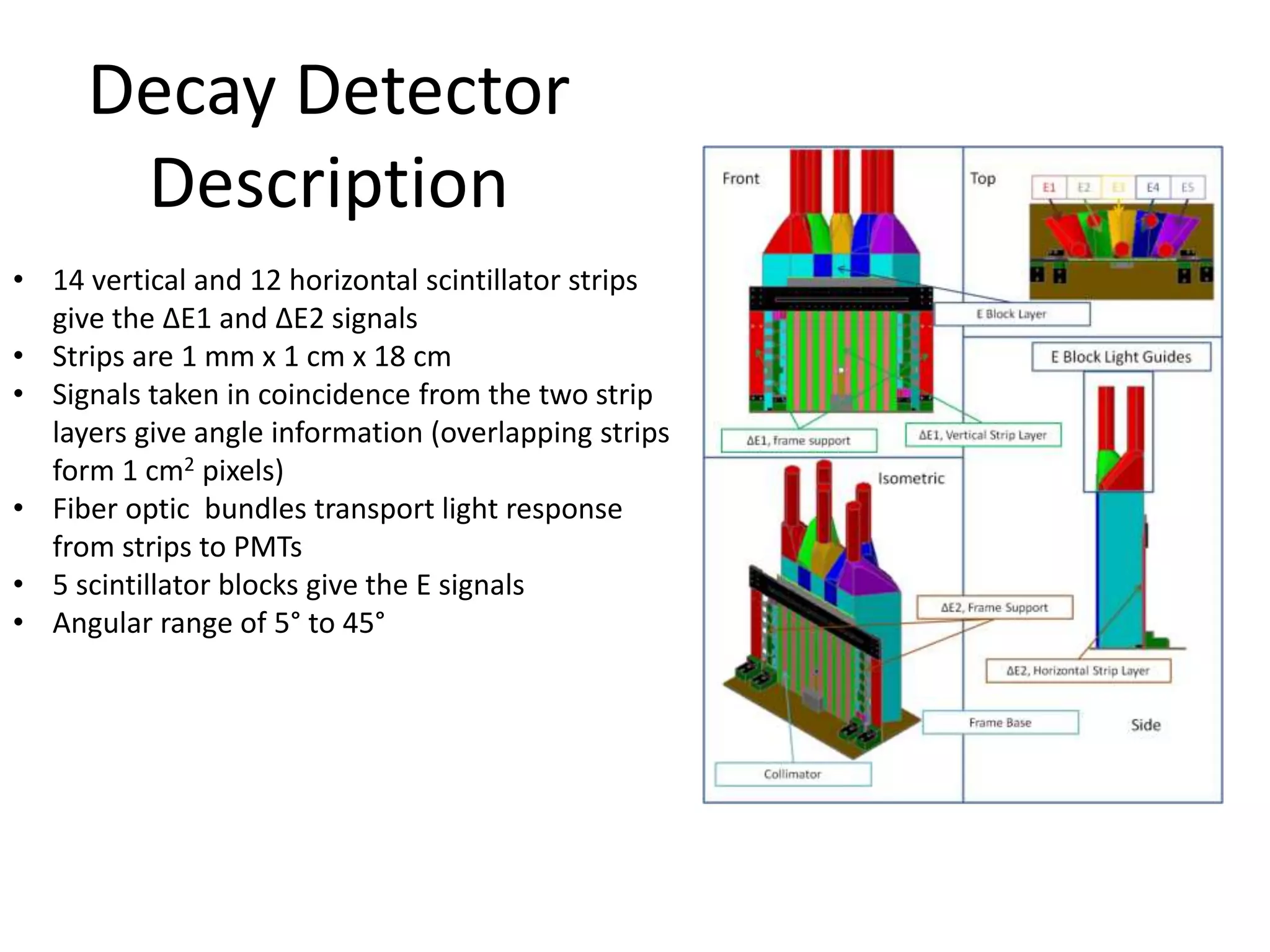
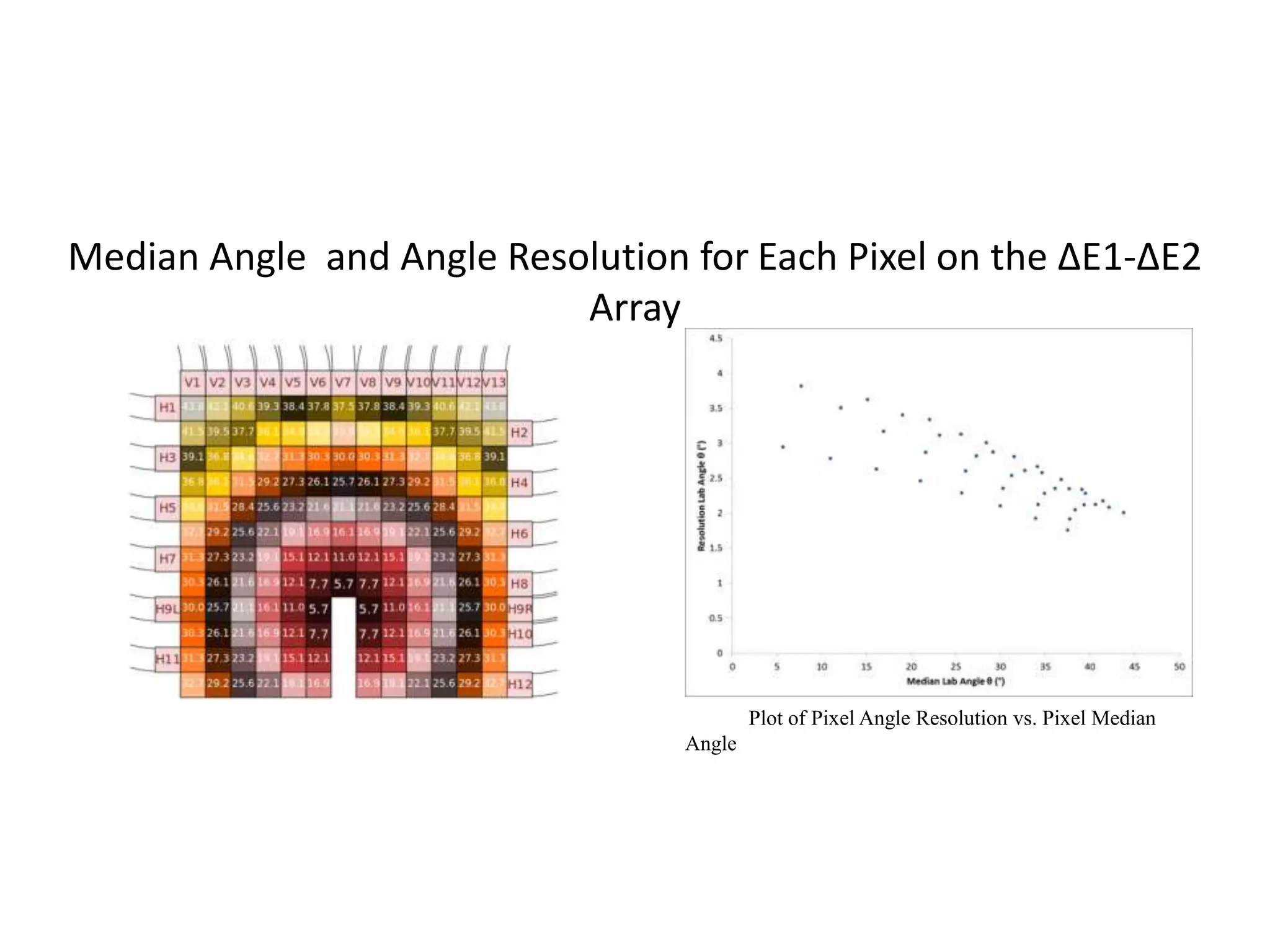
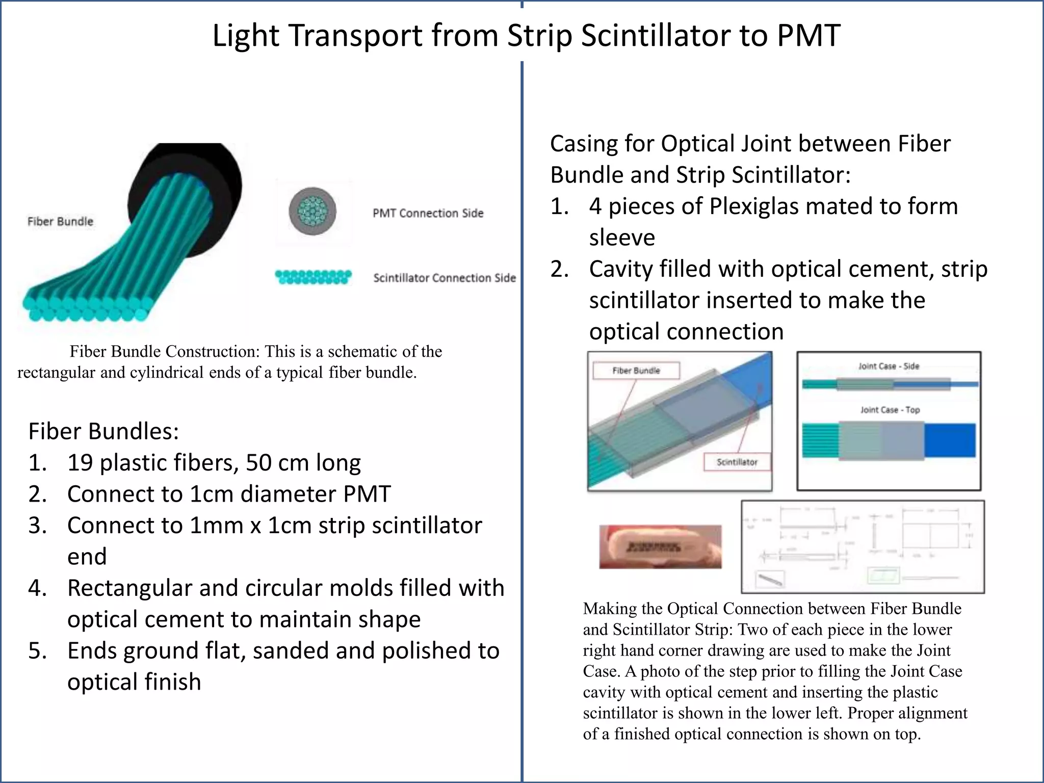
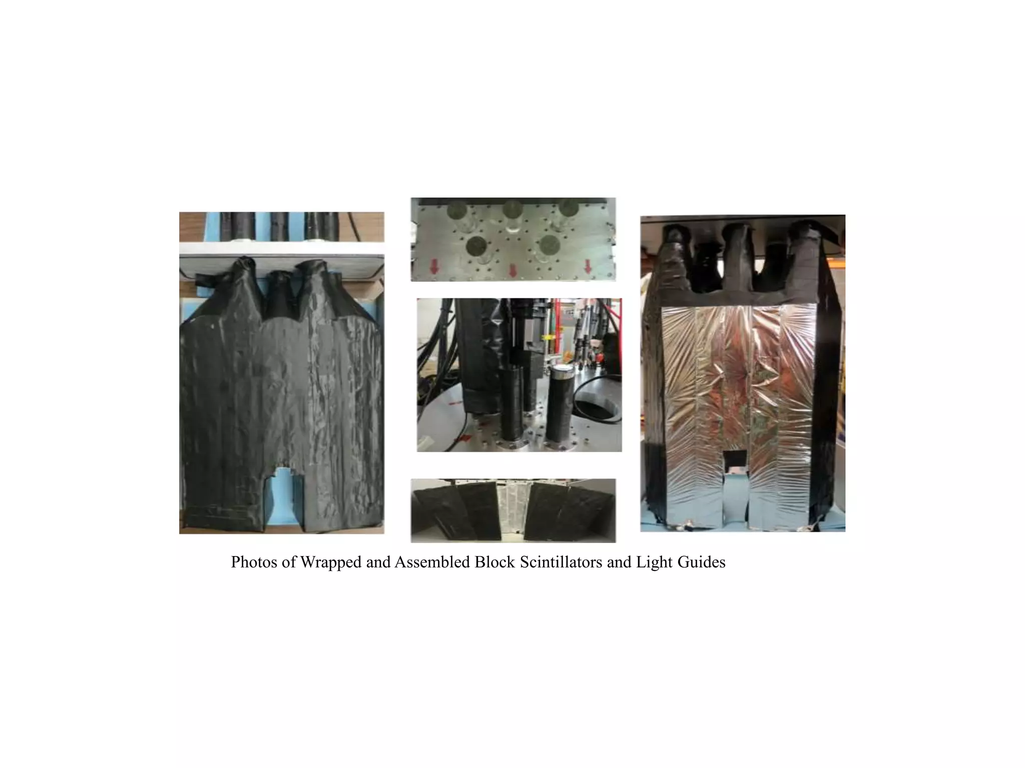
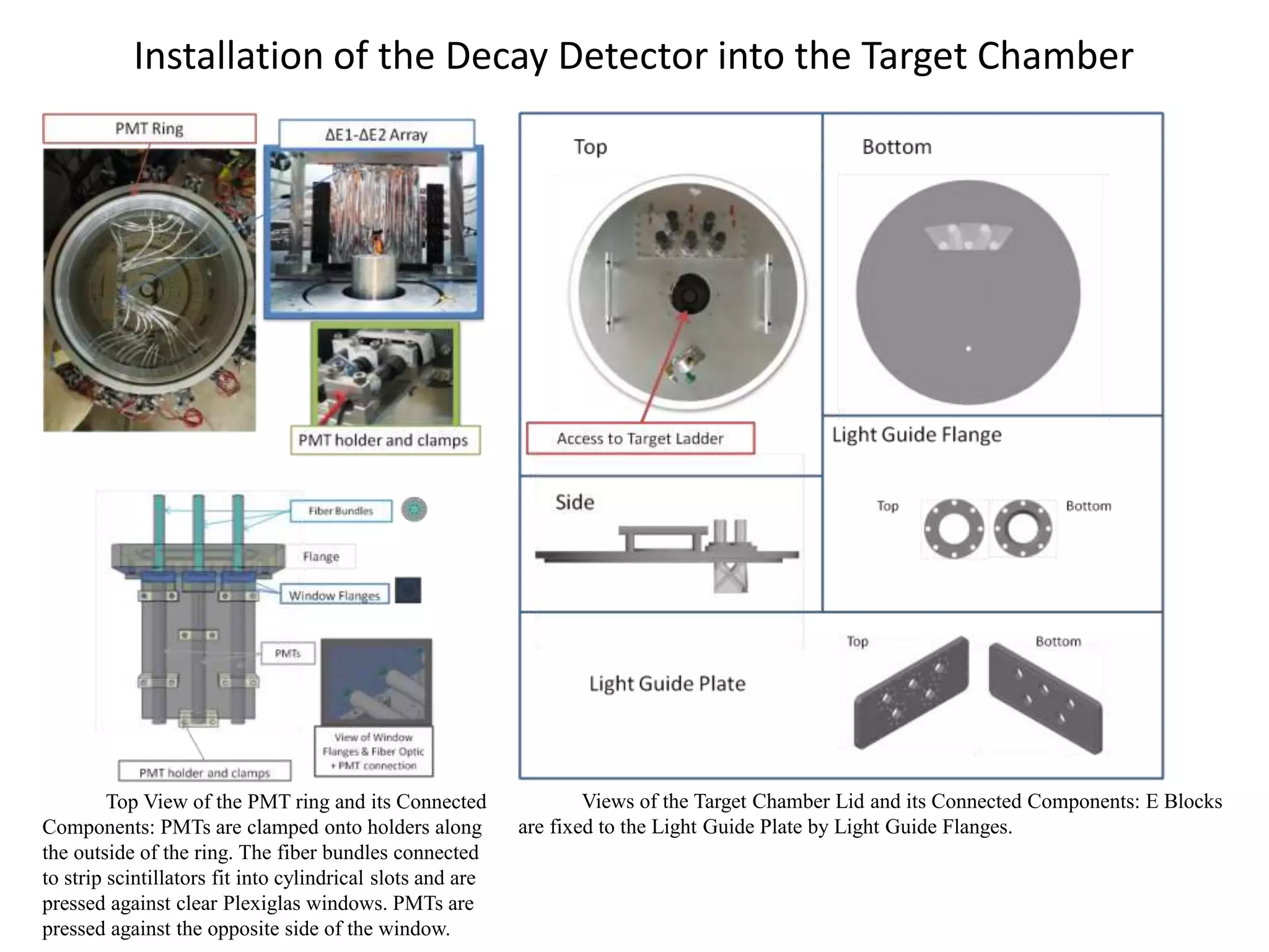
Decay Detector
Description
• 14 vertical and 12 horizontal scintillator strips
give the ΔE1 and ΔE2 signals
• Strips are 1 mm x 1 cm x 18 cm
• Signals taken in coincidence from the two strip
layers give angle information (overlapping strips
form 1 cm2 pixels)
• Fiber optic bundles transport light response
from strips to PMTs
• 5 scintillator blocks give the E signals
• Angular range of 5° to 45°
Plot of Pixel Angle Resolution vs. Pixel Median
Angle
Median Angle and Angle Resolution for Each Pixel on the ΔE1-ΔE2
Array
Fiber Bundle Construction: This is a schematic of the
rectangular and cylindrical ends of a typical fiber bundle.
Making the Optical Connection between Fiber Bundle
and Scintillator Strip: Two of each piece in the lower
right hand corner drawing are used to make the Joint
Case. A photo of the step prior to filling the Joint Case
cavity with optical cement and inserting the plastic
scintillator is shown in the lower left. Proper alignment
of a finished optical connection is shown on top.
Fiber Bundles:
1. 19 plastic fibers, 50 cm long
2. Connect to 1cm diameter PMT
3. Connect to 1mm x 1cm strip scintillator
end
4. Rectangular and circular molds filled with
optical cement to maintain shape
5. Ends ground flat, sanded and polished to
optical finish
Casing for Optical Joint between Fiber
Bundle and Strip Scintillator:
1. 4 pieces of Plexiglas mated to form
sleeve
2. Cavity filled with optical cement, strip
scintillator inserted to make the
optical connection
Light Transport from Strip Scintillator to PMT
Photos of Wrapped and Assembled Block Scintillators and Light Guides
Design for the E3 Block Light Guide: The geometry of the
light guide comes from the intersection of a 2.5” tall
extrusion of the scintillator shape with an eccentric cone.
GuideIt Simulation Results
Light transmission through the odd-
shaped light guides is optimized for light
guide height of 2.5”
Top View of the PMT ring and its Connected
Components: PMTs are clamped onto holders along
the outside of the ring. The fiber bundles connected
to strip scintillators fit into cylindrical slots and are
pressed against clear Plexiglas windows. PMTs are
pressed against the opposite side of the window.
Views of the Target Chamber Lid and its Connected Components: E Blocks
are fixed to the Light Guide Plate by Light Guide Flanges.
Installation of the Decay Detector into the Target Chamber

Decay Detector Description

  • 1.
    Decay Detector Description • 14vertical and 12 horizontal scintillator strips give the ΔE1 and ΔE2 signals • Strips are 1 mm x 1 cm x 18 cm • Signals taken in coincidence from the two strip layers give angle information (overlapping strips form 1 cm2 pixels) • Fiber optic bundles transport light response from strips to PMTs • 5 scintillator blocks give the E signals • Angular range of 5° to 45°
  • 2.
    Plot of PixelAngle Resolution vs. Pixel Median Angle Median Angle and Angle Resolution for Each Pixel on the ΔE1-ΔE2 Array
  • 3.
    Fiber Bundle Construction:This is a schematic of the rectangular and cylindrical ends of a typical fiber bundle. Making the Optical Connection between Fiber Bundle and Scintillator Strip: Two of each piece in the lower right hand corner drawing are used to make the Joint Case. A photo of the step prior to filling the Joint Case cavity with optical cement and inserting the plastic scintillator is shown in the lower left. Proper alignment of a finished optical connection is shown on top. Fiber Bundles: 1. 19 plastic fibers, 50 cm long 2. Connect to 1cm diameter PMT 3. Connect to 1mm x 1cm strip scintillator end 4. Rectangular and circular molds filled with optical cement to maintain shape 5. Ends ground flat, sanded and polished to optical finish Casing for Optical Joint between Fiber Bundle and Strip Scintillator: 1. 4 pieces of Plexiglas mated to form sleeve 2. Cavity filled with optical cement, strip scintillator inserted to make the optical connection Light Transport from Strip Scintillator to PMT
  • 4.
    Photos of Wrappedand Assembled Block Scintillators and Light Guides
  • 5.
    Design for theE3 Block Light Guide: The geometry of the light guide comes from the intersection of a 2.5” tall extrusion of the scintillator shape with an eccentric cone. GuideIt Simulation Results Light transmission through the odd- shaped light guides is optimized for light guide height of 2.5”
  • 6.
    Top View ofthe PMT ring and its Connected Components: PMTs are clamped onto holders along the outside of the ring. The fiber bundles connected to strip scintillators fit into cylindrical slots and are pressed against clear Plexiglas windows. PMTs are pressed against the opposite side of the window. Views of the Target Chamber Lid and its Connected Components: E Blocks are fixed to the Light Guide Plate by Light Guide Flanges. Installation of the Decay Detector into the Target Chamber