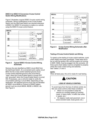
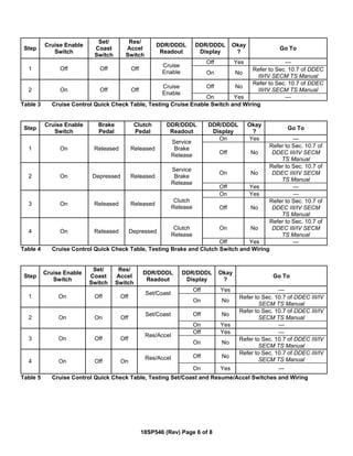
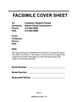
This document provides instructions for installing a conversion kit to update a 1991-1993 Series 60 diesel engine from DDEC II to DDEC IV controls. The kit includes a new ECM, harnesses, sensors and other hardware. The instructions describe removing the old components and installing the new ones, including wiring modifications for cruise control. Tables list the engine models, their original and new control ratings, and part numbers. Completing a fax form is described to update engine records after the conversion. Quick check tables are provided to test the new cruise control components.
Ddec iv on highway - egr application and installationeckardguendel
This document describes the hardware and wiring used in a DDEC IV engine control system for on-highway applications. It discusses the engine sensor harness, vehicle interface harness, electronic control module, sensors, and other components. Wiring diagrams and connector pinouts are provided for the harnesses connecting these components to the ECM. Environmental requirements and part numbers for components are also listed.
This document provides an overview of Detroit Diesel Electronic Controls (DDEC). It discusses the history and features of different DDEC generations. The core components of DDEC are described including the electronic control module, sensors, injectors, and other hardware. Wiring diagrams and functions of various sensors are outlined. The document also reviews governor control systems and troubleshooting tools for DDEC systems.
los diagramas son muy importante que permite a los técnicos para solucionar problemas que se presentan el el circuito eléctrico y utilizar instrumentos para su diagnostico. y el motor opere correctamente de acuerdo a sus datos técnicos.
Jcb t2 t3 mech engine 4 cyl service repair manualujfjjskekkksmem
This service manual section provides information about a JCB T2/3 Mech Engine. It includes technical specifications, component identification diagrams, an overview of the four-stroke engine operating cycle, and procedures for maintenance, repair and storage of the engine. Safety warnings are also provided to caution technicians working on hot or rotating engine components.
The document provides information on exhaust gas recirculation (EGR) components for Series 60 engines, including:
1) The EGR system allows a percentage of exhaust gases to remix with intake air to reduce NOx emissions.
2) Key components include the variable nozzle turbocharger, EGR valve, actuators controlled by the ECM, EGR cooler, and delivery pipes.
3) The variable nozzle turbocharger controls exhaust gas velocity and EGR flow rate. The EGR valve regulates EGR flow via air pressure from the variable pressure output device.
This training manual provides information on servicing and maintaining the Mazda BT-50 pickup truck. It covers the key systems and components of the WL-C diesel engine, including the mechanical features, lubrication system, cooling system, intake and air system, fuel system, exhaust system, emission system, and charging and starting system. Technical specifications and part locations are provided for each system, along with overview diagrams and descriptions of important components like the variable geometry turbocharger, common rail fuel system, and EGR system.
This document provides electrical component information for an excavator, including:
- Component and connector location charts detailing where parts are located on schematics and the machine.
- CID/MID/FMI codes for diagnosing faults in the engine/pump controller, engine controller, and tool controller modules.
- Event codes and their meanings for the engine/pump and engine controllers.
- Specifications for related manuals and an off-machine switch.
This document provides an overview of the hardware and wiring used in Detroit Diesel Corporation's DDEC engine control systems for MBE900 and MBE4000 engines. It describes the engine-resident DDEC-ECU control unit and its engine harness that connects sensors and injectors. The document also discusses the environmental specifications, power supply, and wiring of the DDEC-ECU.
Allison 1000-2000 Series Service Manual.pdfRolandasPetkus
This document provides an overview of the Allison 1000/2000 series transmissions. It describes the key features and components including:
- Five speeds forward with overdrive fifth gear, plus reverse and neutral controlled electronically through six solenoids.
- Planetary gear sets and five clutch packs provide the gear ratios and shifting.
- Fully automatic operation controlled by the transmission control module (TCM).
- Common hydraulic system and oil pump provides pressure for clutches and lubrication.
- Variety of shift selector positions available depending on model and application.
1. The document provides torque specifications for engine components on Detroit Diesel engines, including the air compressor drive gear nut which is specified as 210-250 N·m (155-185 lb·ft).
2. Instructions are given for installing the air compressor, including torquing the drive gear nut to 210-250 N·m and installing coolant and air lines.
3. Precautions are listed to ensure proper installation of the air compressor bolts, coolant lines, and retaining components.
This document provides operating instructions for Mercedes-Benz OM 904-926 LA BlueTec® diesel engines. It contains information on engine components, safety symbols, operating the engine safely and correctly, maintenance procedures, and technical specifications. The instructions emphasize using genuine Mercedes-Benz parts and servicing the engine at authorized workshops. BlueTec® engines require AdBlue® to meet emissions regulations, and operation without it can affect the engine warranty and vehicle approval.
This document provides technical information for repairing NEF power generation engines. It begins with an overview of the NEF engine models and applications. It then discusses fuel types, specific considerations for power generation applications, and overhaul/repair procedures. The document provides detailed instructions and diagrams to guide repairs. Safety precautions are outlined, and conversion tables are included for units of measurement.
Este documento presenta la nueva Actros de Mercedes-Benz. Incluye una introducción y objetivos de aprendizaje, una descripción del exterior e interior del vehículo, y detalles sobre el sistema eléctrico e instrumentos. El documento está protegido por derechos de autor y solo puede usarse para propósitos educativos.
1. The document provides information about the Isuzu 4JH1-TC diesel engine management system, which uses a Bosch VP44 injection pump controlled by an engine control module (ECM) and pump control unit (PSG) that communicate via CAN-bus.
2. The ECM controls fuel injection quantity and timing by exchanging data with the PSG, which actuates the injection pump. They share sensor data and commands via analog signals and CAN-bus.
3. The document outlines the components, electrical circuits, diagnostic procedures and trouble codes for technicians servicing the engine management system.
The document discusses Delphi's products and services for diesel applications in vehicles. It highlights Delphi's complete solutions for fuel systems, engine management, injection, air conditioning and cooling, diagnostics equipment, training and technical support, steering and suspension, and ignition. It emphasizes Delphi's high quality standards from the original equipment market and its ability to provide 100% guarantees on products. It also discusses Delphi's extensive training programs for technicians.
This document is a service manual that describes the common rail fuel injection system for Nissan diesel engines. It provides an overview of the system components and operation, including the supply pump, rail, injectors and engine control unit. The supply pump pressurizes the fuel and controls the pressure using a suction control valve. The rail stores the high-pressure fuel. The injectors control injection timing and rate based on engine ECU commands. The ECU integrates sensor data to optimize injection for cleaner emissions and performance.
O documento lista diversos módulos de controle eletrônico para veículos e fornece detalhes técnicos sobre seus principais componentes e funções. É descrito o funcionamento de módulos Bosch, Siemens, Magneti Marelli e outros para veículos da Peugeot, Citroën, Renault e outros.
Este documento fornece instruções sobre componentes elétricos encontrados em motores Scania. Ele contém informações sobre interruptores, conectores, diodos, unidades eletrônicas, componentes aquecidos, instrumentos, relés, sensores, válvulas solenóide e suas localizações no motor.
Características de diseños del motor e tech motor mackferchung
El documento proporciona información sobre la identificación de motores E-Tech. Describe la placa de información del motor y los bloques que contiene sobre normas de emisiones y especificaciones técnicas. También explica las características clave del motor E-Tech como el sistema de inyección de combustible por bomba unitaria electrónica y el sistema de control electrónico V-MAC III.
El documento describe el aparato de mando E 300 para la caja de cambios DIWA.5. El aparato de mando controla y supervisa las funciones de la caja de cambios, reconociendo la topografía y optimizando los cambios. También registra datos de servicio para análisis y diagnóstico, e informa sobre fallos y eventos. Se conecta a la caja de cambios a través de varios enchufes y sensores para controlar válvulas magnéticas, embragues, frenos y niveles de aceite y temperatura.
DIAGRAMA ELECTRICO INTERACTIVO CAT 336DL Uenr26380001juanManuel1001
This document provides an interactive schematic for a machine. It includes:
- Symbols and definitions for electrical, hydraulic, and other components
- Instructions for setting the screen resolution for best viewing
- Bookmarks panel and hyperlinks to navigate schematic and machine views
- Buttons to zoom, fit to page, and find all callouts
This document provides a wiring manual for the Mahindra Bolero Maxitruck Plus vehicle. It outlines the complete electrical network of the vehicle through wiring diagrams, component locations, fuse layouts and ratings. The manual is intended to help technicians quickly identify and repair electrical issues by understanding how the various electrical systems are integrated and interconnected. It defines the locations of crucial components, color coding of wires, and connectors between harnesses.
DIAGRAMA ELECTRICO 336DL CAT. Renr95870001juanManuel1001
This document provides information on electrical system components and symbols for a 330D and 336D excavator. It includes:
1) A table listing connector and component locations by schematic and machine location.
2) Pages of electrical schematic symbols and their meanings.
3) A section defining harness and wire symbols such as colors, gauges and connector identification codes.
The document is a reference for technicians servicing the excavator's electrical system. It identifies all electrical connectors, components and their machine locations for troubleshooting.
Caterpillar Cat DP30N Forklift Lift Trucks Service Repair Manual SN:T14E-4000...kjkemmd
Here are the key points about the truck models covered in this service manual:
- The service manual provides information for mechanically controlled (MC) and finger-tip controlled (FC) trucks.
- FC type is only used in torque converter models.
- The last characters of the truck model indicate:
- (F): Finger-tip controlled model
- No indication: Mechanically controlled model
- Z: High-power engine model
- C: Short body model
- Truck models are identified by combinations of model code and engine serial number range.
- Engines include gasoline (K-series), diesel (S-series), and LPG.
- Truck classes range from
The document provides instructions for removing the fuel injection pump gear and electronic unit injectors from a Caterpillar C4.4 engine. The procedure for removing the fuel injection pump gear involves using tools to remove the nut, washer, and gear. For the electronic unit injectors, markings are made, fuel lines and electrical connections are disconnected, and tools are used to remove the injectors from the cylinder head. Precautions are outlined to contain fluids and prevent contamination.
This document provides instructions for removing and installing electronic unit injectors on a Caterpillar C4.4 engine. The removal process involves disconnecting fuel lines, electrical connections, and removing mounting hardware. Identification marks should be made to ensure correct reinstallation. Any fuel is drained and lines are capped to prevent contamination. Installation requires cleaning the cylinder, installing new seals and connectors, and reconnecting fuel lines and electrical harness assemblies. The injector code must be programmed into the electronic control module if a new injector is installed.
This document provides instructions for removing and installing electronic unit injectors on a Caterpillar C4.4 engine. The removal process involves disconnecting fuel lines, electrical connections, and removing mounting hardware. Identification marks should be made to ensure correct reinstallation of parts. The installation process begins with evacuating fuel from the cylinder and requires a new injector code to be programmed if an injector is replaced. Proper sealing and torque of mounting hardware is also specified.
This document provides instructions for removing and installing electronic unit injectors on a Caterpillar C4.4 engine. The removal process involves disconnecting fuel lines, removing electrical connections, and using tools to pry the injectors from the cylinder head. New seals must be installed before inserting the injectors. Wiring harnesses are also removed and reinstalled. Precautions are outlined to contain fluids and prevent contamination of fuel system components.
The document provides instructions for removing the fuel injection pump gear and electronic unit injectors from a Caterpillar C4.4 engine. The procedure for removing the fuel injection pump gear involves using tools to remove the nut, washer, and gear. To remove the electronic unit injectors, the fuel supply is turned off, connections are disconnected, identification marks are made, seals are removed, and tools are used to pry the injectors from the cylinder head. Precautions are outlined to contain fluids and prevent contamination.
This document provides instructions for removing and installing electronic unit injectors on a Caterpillar C4.4 engine. The removal process involves disconnecting fuel lines, removing electrical connections, and using tools to pry the injectors from the cylinder head. New seals must be installed before inserting the injectors. Wiring harnesses are also removed and reinstalled. Precautions are outlined to contain fluids and prevent contamination of fuel system components.
262D3 CATERPILLAR SKID STEER LOADER SERVICE REPAIR MANUAL ZB2Manual Labs
The 262D3 Caterpillar Skid Steer Loader Service Repair Manual provides you with detailed service information, step-by-step instructions, and maintenance specifications for your 264D3 equipment. Expert workshops and service technicians can rely on this comprehensive manual for accurate and in-depth repair and maintenance.
This document provides instructions for removing the engine oil filter base from a Caterpillar 962G wheel loader with a 3126 engine. The procedure involves first removing the turbocharger. Then, using a strap wrench, loosening and removing the oil filter base. Cleanliness is emphasized to prevent contamination.
This document provides instructions for removing the engine oil filter base from a Caterpillar 962G wheel loader. The procedure involves first removing the turbocharger. Then, using a strap wrench, loosening and removing the oil filter base. Cleanliness is emphasized to prevent contamination.
This document provides instructions for removing and installing inlet and exhaust valves, valve guides, and valve seat inserts on a Caterpillar 962G wheel loader with a 3126 engine. The removal and installation procedures are described in steps and include required tools. Notes are provided regarding part reusability and keeping parts clean to prevent wear.
This document provides instructions for removing the engine oil filter base from a Caterpillar 962G wheel loader with a 3126 engine. The procedure involves first removing the turbocharger. Then, using a strap wrench, loosening and removing the oil filter base. Cleanliness is emphasized to prevent contamination.
This document provides instructions for removing and installing inlet and exhaust valves, valve guides, and valve seat inserts on a 962G wheel loader powered by a 3126 engine. The removal and installation procedures are described in steps and include required tools. Special notes are provided regarding keeping parts clean and guidelines for determining if parts can be reused.
This document provides instructions for removing the engine oil filter base from a Caterpillar 962G wheel loader with a 3126 engine. The procedure involves first removing the turbocharger. Then, using a strap wrench, loosening and removing the oil filter base. Cleanliness is emphasized to prevent contamination.
This document provides instructions for removing the engine oil filter base from a Caterpillar 962G wheel loader. The procedure involves first removing the turbocharger. Then, using a strap wrench, loosening and removing the oil filter base. Cleanliness is emphasized to prevent contamination.
This document provides instructions for removing the engine oil filter base from a Caterpillar 962G wheel loader with a 3126 engine. The procedure involves first removing the turbocharger. Then, using a strap wrench, loosening and removing the oil filter base. Cleanliness is emphasized to prevent contamination.
Caterpillar cat 322 c fm excavator (prefix cam) service repair manual (cam000...fjjkefkksem
This document provides instructions for removing and installing inlet and exhaust valve seats in a 322C FM excavator. The procedure includes using a valve seat extractor tool to remove the seats from the cylinder head. New seats should be installed and lubricated before reinstalling the valves and cylinder head. Precautions are given to keep parts clean and refer to specifications on reusable components.
279D3 CATERPILLAR COMPACT TRACK LOADER SERVICE REPAIR MANUAL RB9 PDF DOWNLOADManual Labs
This official service manual for the 279D3 Caterpillar Compact Track Loader provides operators and technicians comprehensive technical information to safely, quickly, and easily troubleshoot their equipment. It includes highly detailed information and diagrams for all service and repair procedures. Save time and money by downloading this manual today.
Fleet management these days is next to impossible without connected vehicle solutions. Why? Well, fleet trackers and accompanying connected vehicle management solutions tend to offer quite a few hard-to-ignore benefits to fleet managers and businesses alike. Let’s check them out!
Implementing ELDs or Electronic Logging Devices is slowly but surely becoming the norm in fleet management. Why? Well, integrating ELDs and associated connected vehicle solutions like fleet tracking devices lets businesses and their in-house fleet managers reap several benefits. Check out the post below to learn more.
The Octavia range embodies the design trend of the Škoda brand: a fusion of
aesthetics, safety and practicality. Whether you see the car as a whole or step
closer and explore its unique features, the Octavia range radiates with the
harmony of functionality and emotion
What Could Be Behind Your Mercedes Sprinter's Power Loss on Uphill RoadsSprinter Gurus
Unlock the secrets behind your Mercedes Sprinter's uphill power loss with our comprehensive presentation. From fuel filter blockages to turbocharger troubles, we uncover the culprits and empower you to reclaim your vehicle's peak performance. Conquer every ascent with confidence and ensure a thrilling journey every time.
1. 18SP546* – Install DDEC II to DDEC IV Wire Harness and
Hardware Conversion Kit on 1991-1993 Series 60®
On-Highway Manual Transmission Trucks
*Revision – 12/14/04
Introduction
Service kit R23529490 permits conversion of a Detroit
Diesel Series 60® DDEC® II engine to a DDEC IV
configuration. The kit includes the items listed in
Table 1.
Kit Part Number Qty. Description
R23519307 1 ECM
23512307 8 Isolator
23513558 1 Engine Harness
23517986 1 Power Harness Adaptor
23518358 1 Injector Harness, Jake
Brake®
23520380 1 Coolant Level Sensor
(CLS)- 1/4” -18 NPTF
23520381 1 Coolant Level Sensor
(CLS) - 3/8”-18 NPTF
23518206 1 Adaptor Module, Coolant
Level Sensor
23518359 1 Harness Asm., Coolant
Level Sensor Jumper
Liner
23515251 1 Coolant Temperature
Sensor (CTS) - ¾ in.
brass
23519124 1 Heat Shield, Exh.
Manifold
23509744 3 Stud Bolt, M10, 1.5x120
11506101 3 Nut, M10
23515250 1 Air Temperature Sensor
(ATS)
23517875 3 Intake Manifold Gasket
18SP546 1 Installation Instructions
Table 1 DDEC II to DDEC IV Conversion Kit,
P/N: 23529490
Following are instructions for installing the parts in the
kit. Refer to the current Series 60 Service Manual,
6SE483 and the DDEC III/IV SECM Troubleshooting
Guide, 6SE497 for instructions on removing, installing,
and testing the other parts required for kit installation.
DDEC II ECM Removal
Remove the ECM as follows:
PERSONAL INJURY
To avoid injury from hot surfaces, wear
protective gloves, or allow engine to cool
before removing any component.
PERSONAL INJURY
To avoid injury from accidental startup
while servicing the engine, disconnect the
starting system.
1. With the engine at ambient temperature (cool to
the touch) and the starting system disconnected/
disabled, disconnect the power harness from
vehicle batteries.
2. Loosen the wire harness connector hold-down
screws, and gently disengage the connectors
from ECM sockets.
3. Remove the DDEC II injector and engine
sensor harness from the engine.
18SP546 (Rev) Page 1 of 8
2. 4. Loosen the wire harness connector hold-down
screws, gently disengage connectors, and
remove DDEC II ECM from vehicle.
DDEC IV ECM Installation
Conversion kit components are listed in Table 1. Refer
to the Series 60 Service Manual and install parts as
follows:
1. Install the Engine Sensor Harness (P/N:
23513558), included in the kit. See Figure 1. Refer
to Section 8.6 of Service Manual.
2. Install the Injector/Jake Brake® harness
(P/N: 23518358) included in the kit.
3. Install new Coolant Level Sensor (CLS) (either ¼”
P/N: 23520380 or 3/8” P/N; 23520381). Refer to
Section 2.34 of Service Manual.
4. Install the CLS adaptor module (P/N: 23518206)
and jumper adaptor (P/N: 23518359).
5. Install the Coolant Temperature Sensor (CTS)
(P/N: 23515251) at right rear of head. Refer to
Section 2.31 of Service Manual.
6. Install the heat shield (P/N: 23519124) using stud
bolts (P/N: 23509744) and nuts (P/N: 11506101).
a) If the engine has current exhaust manifold,
install heat shield “as is.”
b) If the engine has former style manifold, the heat
shield may need to be altered prior to
installation.
7. Remove the air intake manifold and discard old
gaskets.
8. Using a drill press and a 9/16” drill, drill and tap a
3/8” pipe port for the Air Temperature Sensor
(ATS), between #3 and #4 intake air ports in
manifold. See Figure 2.
9. Clean the air intake manifold thoroughly to remove
drill chaff.
10. Install ATS (P/N: 23515250). Torque to 11-16 N·m
(8-12 lb·ft).
11. Using new gaskets (P/N: 23517875), install the air
intake manifold.
PERSONAL INJURY
Diesel engine exhaust and some of its
constituents are known to the State of
California to cause cancer, birth defects,
and other reproductive harm.
• Always start and operate an engine in
a well ventilated area.
• If operating an engine in an enclosed
area, vent the exhaust to the outside.
• Do not modify or tamper with the
exhaust system or emission control
system.
12. Reconnect starting power. Start the engine and
check for proper DDEC system operation.
Figure 1 DDEC IV ECM and Wiring Harness
Locations
Figure 2 Air Temperature Sensor Location
18SP546 (Rev) Page 2 of 8
3. Powernet Engine Order Entry,
Change Unit Information
In order for the newly installed DDEC IV ECM to be
programmed, a mainframe file must be established. To
ensure that the ability to program the DDEC IV ECM is
established, the attached FAX form (See Figure 5) must
be filled out and sent to the DDC Customer Support
Center at (313) 592-5888. See Table 2 for the
appropriate 6N4D and 6N4M groups.
Important Information – Please read.
You must use the updated fax request in these
instructions, or request the mainframe update to “DDEC
IV,” otherwise the wrong calibration could be assigned.
The DDEC IV ECM in this kit is only for use with
12-volt systems.
Within the ratings listed, you will find the original DDEC
II-III ratings and a cross-reference to the comparable
DDEC IV version.
With the following features now found within the DDEC
system, it is possible to cover a wide variety of requests
with fewer ratings:
• Low gear torque limiting will modify the max.
torque for the application.
• Progressive shift will limit the max RPM for the
user.
NOTE:
Vehicle speed sensors must be used for these two
features to operate properly.
For example, there is only one DDEC IV rating released
for the 11 liter engines: 6N4D7275 is a 400/357 @
1800/2100-1350 lb·ft.
To reduce the maximum torque from 1350 to 1250 lb·ft:
• Set the low gear torque limit to 1250
• Set the threshold to 0.1
To reduce the maximum rated speed from 2100 to
1800 rpm, set progressive shift as follows:
• LG1 rpm limit - 1800
• LG1 max rpm - 1800
• LG1 max mph - 12
• LG2 rpm limit - 1800
• LG2 max rpm - 1800
• LG2 max mph - 44
• HG max rph - 1800
• HG min mph - 45
DDEC II to DDEC IV UPC groups are listed in Table 2.
To ensure that the engine is serviced properly after
being converted from DDEC II to DDEC IV, and to
ensure that other modifications may be made, DDC’s
unit history file must be updated. If this is not done,
subsequent engine service and/or repair work might be
done using incorrect parts. Complete the attached FAX
form and send it to the DDC Customer Support Center.
See Figure 5.
18SP546 (Rev) Page 3 of 8
5. DDEC II to DDEC IV Conversion Cruise Control
Switch Wiring Modifications
Figure 3 illustrates a typical DDEC II cruise control wiring
schematic. Wiring modifications to the Cruise Enable
Switch and the Set/Coast Switch are required whenever
a DDEC II to DDEC IV conversion is made on a vehicle
using the DDEC II cruise control feature.
Figure 3 Typical DDEC II Cruise Control Wiring
Schematic
Remove the wire identified as DDEC circuit #542 from
the Set/Coast Switch. At a convenient point, splice circuit
#542 into the cruise control switched ground circuit.
Cruise control switched ground is the circuit that is
“open” when the Cruise Enable Switch is turned OFF
and “grounded” when the Cruise Enable Switch is turned
ON. If necessary, use a volt-ohm meter to verify the
circuit before splicing in circuit #542. Depending on the
application, the switched ground circuit may be identified
as DDEC circuit #558 or a branch of DDEC battery
ground, such as circuit #953A, #953B, or #953C, etc.
See Figure 4.
Figure 4 Cruise Control Wiring Schematic after
Modification
Testing of Cruise Control Switch and Wiring
To speed up the testing of cruise control switches, quick
check tables have been developed. These tests are to
be run with the ignition ON, and the engine not running.
A DDR / DDDL must be plugged into the connector. All
three quick check tables must be completed to properly
check the cruise control wiring and switches.
See Tables 3, 4 and 5.
NOTE:
When all tests pass, the unit is ready for road testing.
LOSS OF VEHICLE CONTROL
To avoid injury from the loss of vehicle control, do
Not use cruise control under these conditions:
• When it is not possible to keep the
vehicle at a constant speed (on winding
roads, in heavy traffic, in traffic that varies
in speed, etc.)
• On slippery roads (wet pavement, ice-or
snow-covered roads, loose gravel, etc.)
18SP546 (Rev) Page 5 of 8
6. Step
Cruise Enable
Switch
Set/
Coast
Switch
Res/
Accel
Switch
DDR/DDDL
Readout
DDR/DDDL
Display
Okay
?
Go To
Off Yes —
1 Off Off Off
Cruise
Enable On No
Refer to Sec. 10.7 of DDEC
III/IV SECM TS Manual
Off No
Refer to Sec. 10.7 of DDEC
III/IV SECM TS Manual2 On Off Off
Cruise
Enable
On Yes —
Table 3 Cruise Control Quick Check Table, Testing Cruise Enable Switch and Wiring
Step
Cruise Enable
Switch
Brake
Pedal
Clutch
Pedal
DDR/DDDL
Readout
DDR/DDDL
Display
Okay
?
Go To
On Yes —
1 On Released Released
Service
Brake
Release Off No
Refer to Sec. 10.7 of
DDEC III/IV SECM
TS Manual
On No
Refer to Sec. 10.7 of
DDEC III/IV SECM
TS Manual
2 On Depressed Released
Service
Brake
Release
Off Yes —
On Yes —
3 On Released Released
Clutch
Release Off No
Refer to Sec. 10.7 of
DDEC III/IV SECM
TS Manual
On No
Refer to Sec. 10.7 of
DDEC III/IV SECM
TS Manual
4 On Released Depressed
Clutch
Release
Off Yes —
Table 4 Cruise Control Quick Check Table, Testing Brake and Clutch Switch and Wiring
Step
Cruise Enable
Switch
Set/
Coast
Switch
Res/
Accel
Switch
DDR/DDDL
Readout
DDR/DDDL
Display
Okay
?
Go To
Off Yes —
1 On Off Off
Set/Coast
On No
Refer to Sec. 10.7 of DDEC III/IV
SECM TS Manual
Off No
Refer to Sec. 10.7 of DDEC III/IV
SECM TS Manual2 On On Off
Set/Coast
On Yes —
Off Yes —
3 On Off Off
Res/Accel
On No
Refer to Sec. 10.7 of DDEC III/IV
SECM TS Manual
Off No
Refer to Sec. 10.7 of DDEC III/IV
SECM TS Manual4 On Off On
Res/Accel
On Yes —
Table 5 Cruise Control Quick Check Table, Testing Set/Coast and Resume/Accel Switches and Wiring
18SP546 (Rev) Page 6 of 8