3.1 DIGITAL-TO-ANALOG CONVERSION
•It is the process of changing one of the characteristics of an
analog signal based on the information in digital data.
• Figure 5.1 shows the relationship between the digital
information, the digital-to-analog modulating process, and the
resultant analog signal.
4.
3.1 DIGITAL-TO-ANALOG CONVERSION
•sine wave is defined by three characteristics: amplitude,
frequency, and phase.
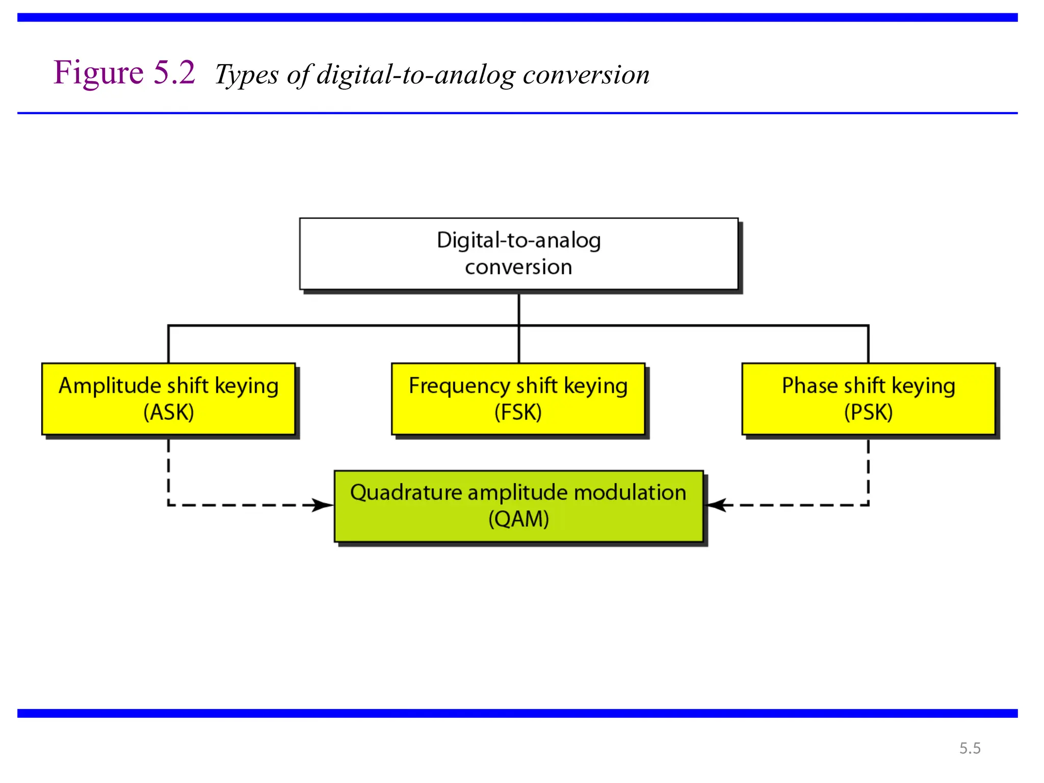
• Any of the three characteristics can be altered in this way,
giving us at least three mechanisms for modulating digital
data into an analog signal: amplitude shift keying (ASK),
frequency shift keying (FSK), and phase shift keying
(PSK).
• A mechanism that combines changing both the amplitude and
phase, called quadrature amplitude modulation (QAM).
QAM is the most efficient of these options and is the
mechanism commonly used today
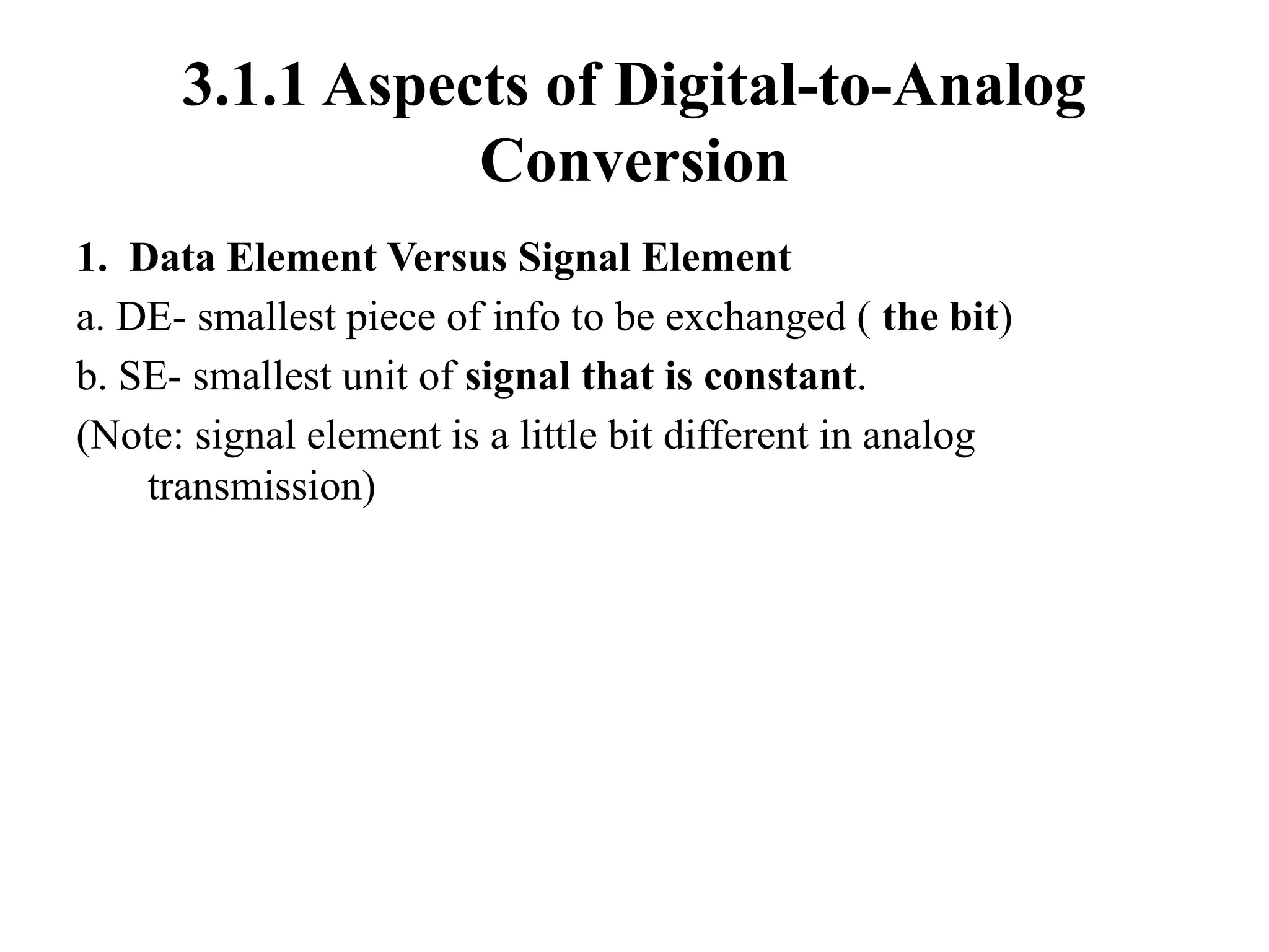
3.1.1 Aspects ofDigital-to-Analog
Conversion
1. Data Element Versus Signal Element
a. DE- smallest piece of info to be exchanged ( the bit)
b. SE- smallest unit of signal that is constant.
(Note: signal element is a little bit different in analog
transmission)
7.
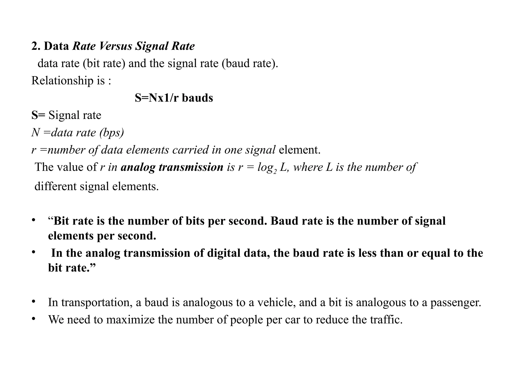
2. Data RateVersus Signal Rate
data rate (bit rate) and the signal rate (baud rate).
Relationship is :
S=Nx1/r bauds
S= Signal rate
N =data rate (bps)
r =number of data elements carried in one signal element.
The value of r in analog transmission is r = log2 L, where L is the number of
different signal elements.
• “Bit rate is the number of bits per second. Baud rate is the number of signal
elements per second.
• In the analog transmission of digital data, the baud rate is less than or equal to the
bit rate.”
• In transportation, a baud is analogous to a vehicle, and a bit is analogous to a passenger.
• We need to maximize the number of people per car to reduce the traffic.
8.
5.8
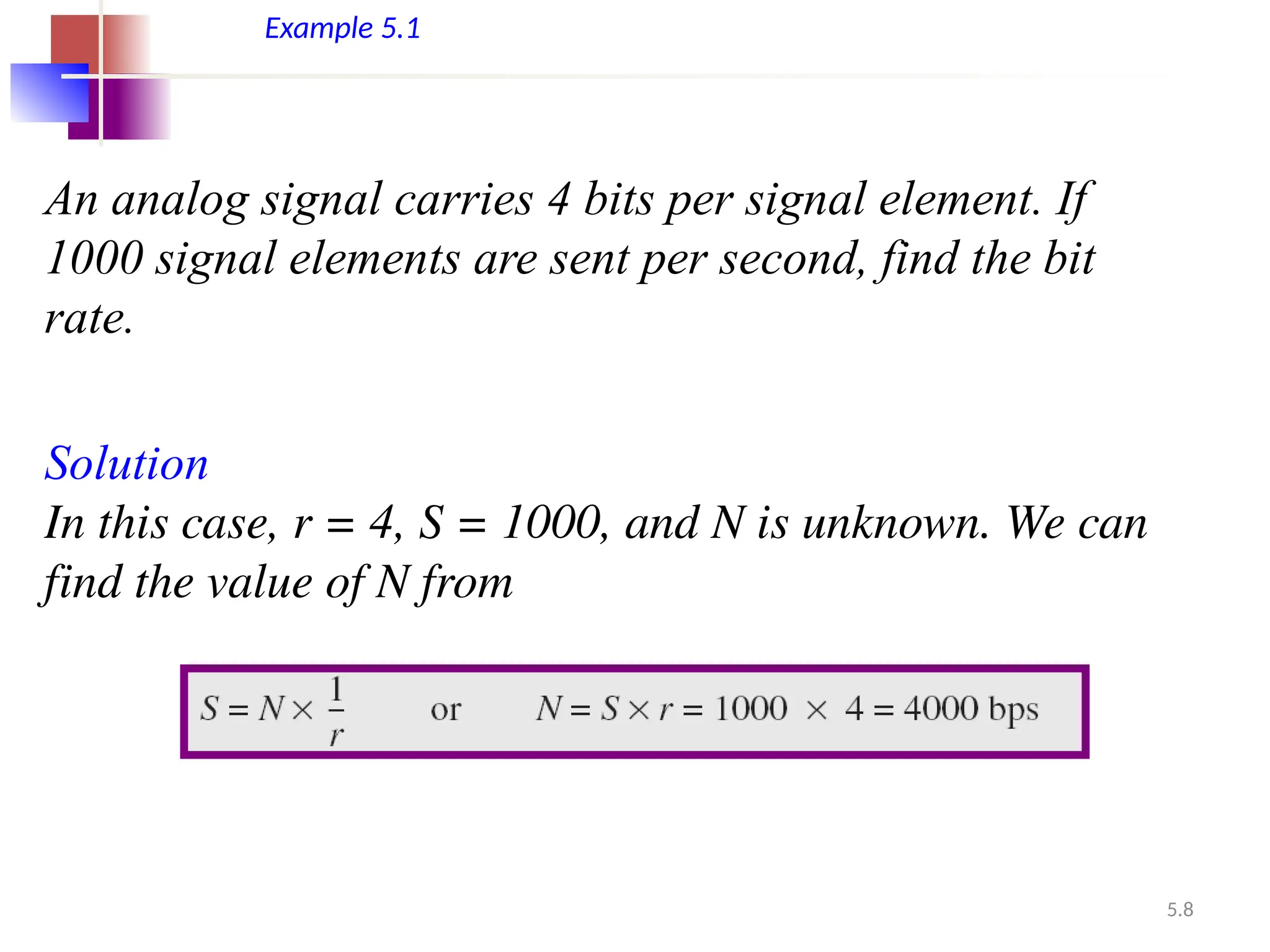
An analog signalcarries 4 bits per signal element. If
1000 signal elements are sent per second, find the bit
rate.
Solution
In this case, r = 4, S = 1000, and N is unknown. We can
find the value of N from
Example 5.1
9.
5.9
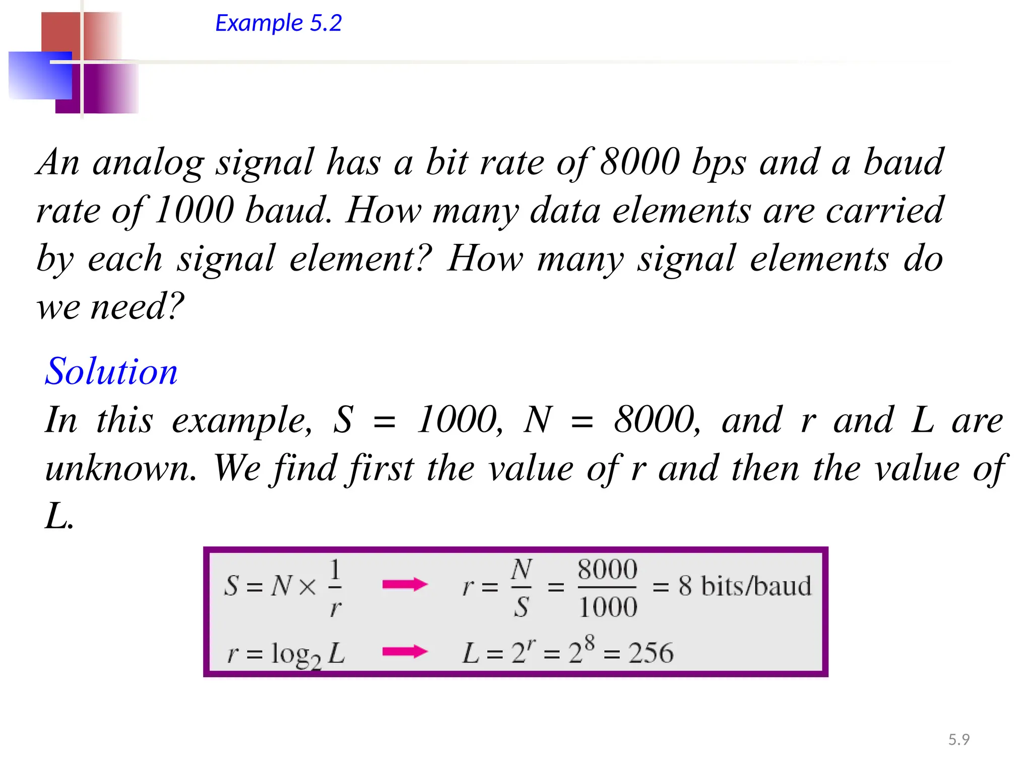
Example 5.2
An analogsignal has a bit rate of 8000 bps and a baud
rate of 1000 baud. How many data elements are carried
by each signal element? How many signal elements do
we need?
Solution
In this example, S = 1000, N = 8000, and r and L are
unknown. We find first the value of r and then the value of
L.
10.
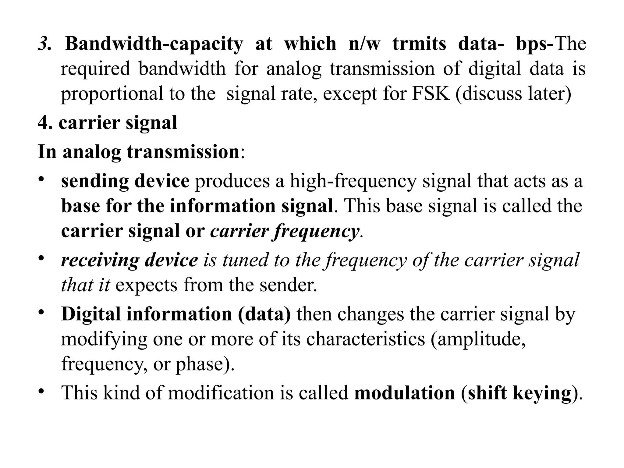
3. Bandwidth-capacity atwhich n/w trmits data- bps-The
required bandwidth for analog transmission of digital data is
proportional to the signal rate, except for FSK (discuss later)
4. carrier signal
In analog transmission:
• sending device produces a high-frequency signal that acts as a
base for the information signal. This base signal is called the
carrier signal or carrier frequency.
• receiving device is tuned to the frequency of the carrier signal
that it expects from the sender.
• Digital information (data) then changes the carrier signal by
modifying one or more of its characteristics (amplitude,
frequency, or phase).
• This kind of modification is called modulation (shift keying).
11.
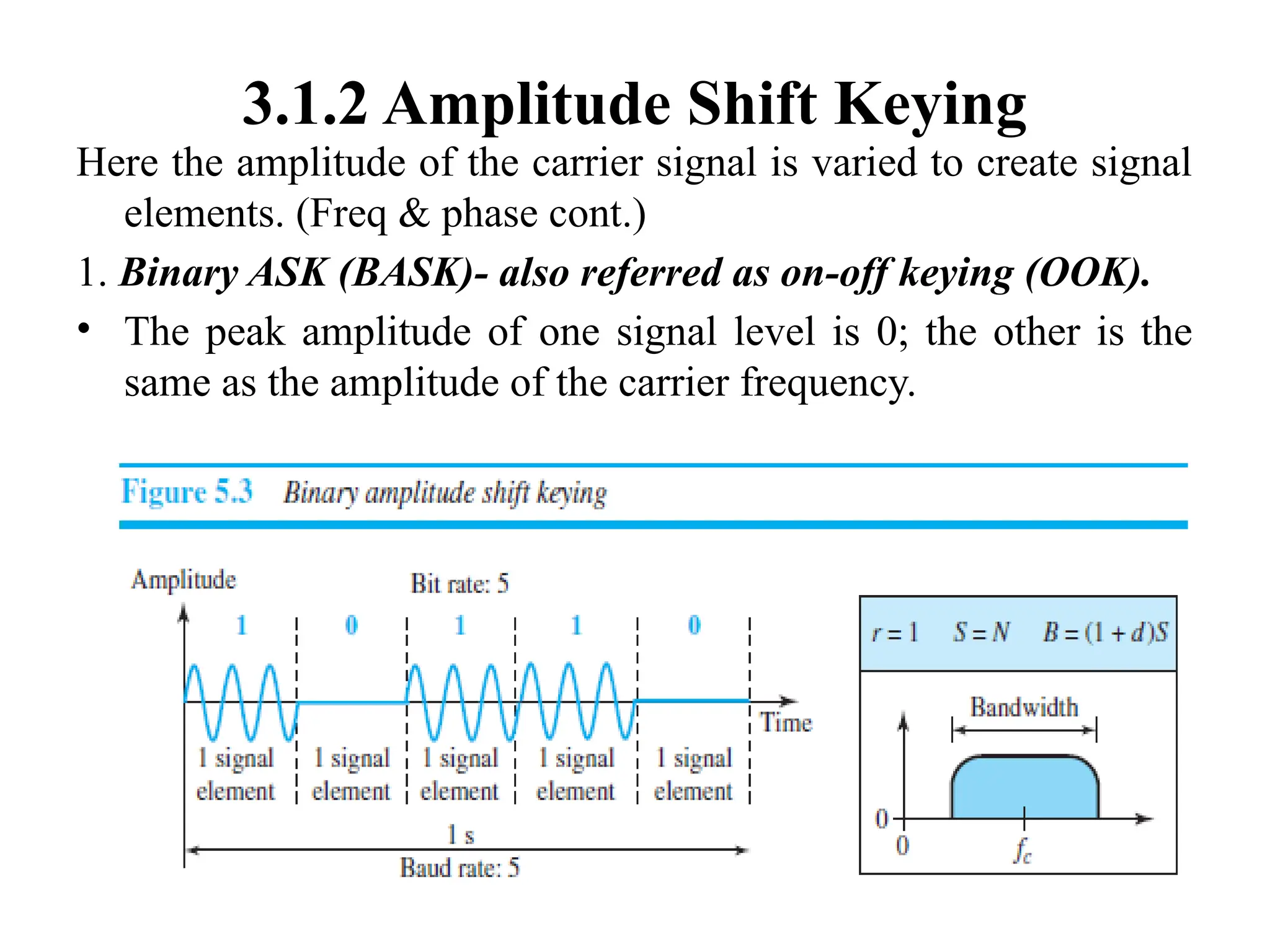
3.1.2 Amplitude ShiftKeying
Here the amplitude of the carrier signal is varied to create signal
elements. (Freq & phase cont.)
1. Binary ASK (BASK)- also referred as on-off keying (OOK).
• The peak amplitude of one signal level is 0; the other is the
same as the amplitude of the carrier frequency.
12.
• Although thecarrier signal is only one simple sine wave, the process
of modulation produces a nonperiodic composite signal.
• The bandwidth B of ASK is proportional to the signal rate S (baud
rate).
B = (1+d) x S
• “d” is factor, due to modulation and filtering, lies between 0 and 1.
• The formula shows that the required bandwidth has a minimum
value of S and a maximum value of 2S.
• The most important point here is the location of the bandwidth.
The middle of the bandwidth is where fc, the carrier frequency, is
located.
• This means if we have a bandpass channel available, we can
choose our fc so that the modulated signal occupies that
bandwidth.
13.
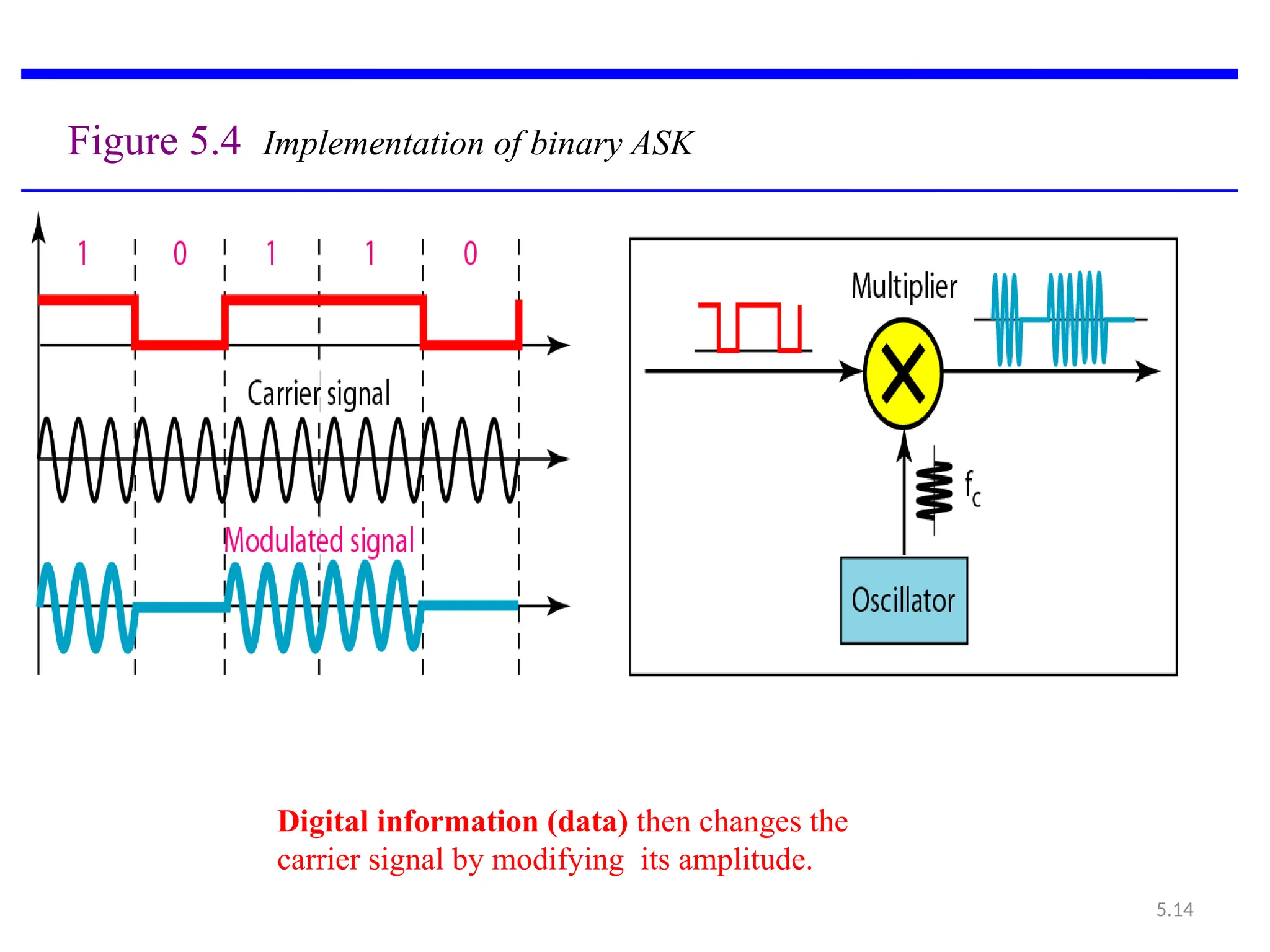
Implementation of binaryASK
• simple ideas- If digital data are presented as a unipolar NRZ,
digital signal with a high voltage of 1 V and a low voltage of
0 V, the implementation can be achieved by multiplying the
NRZ digital signal by the carrier signal coming from an
oscillator.
• When the amplitude of the NRZ signal is 1, the amplitude of
the carrier frequency is held; when the amplitude of the NRZ
signal is 0, the amplitude of the carrier frequency is zero.
14.
5.14
Figure 5.4 Implementationof binary ASK
Digital information (data) then changes the
carrier signal by modifying its amplitude.
15.
5.15
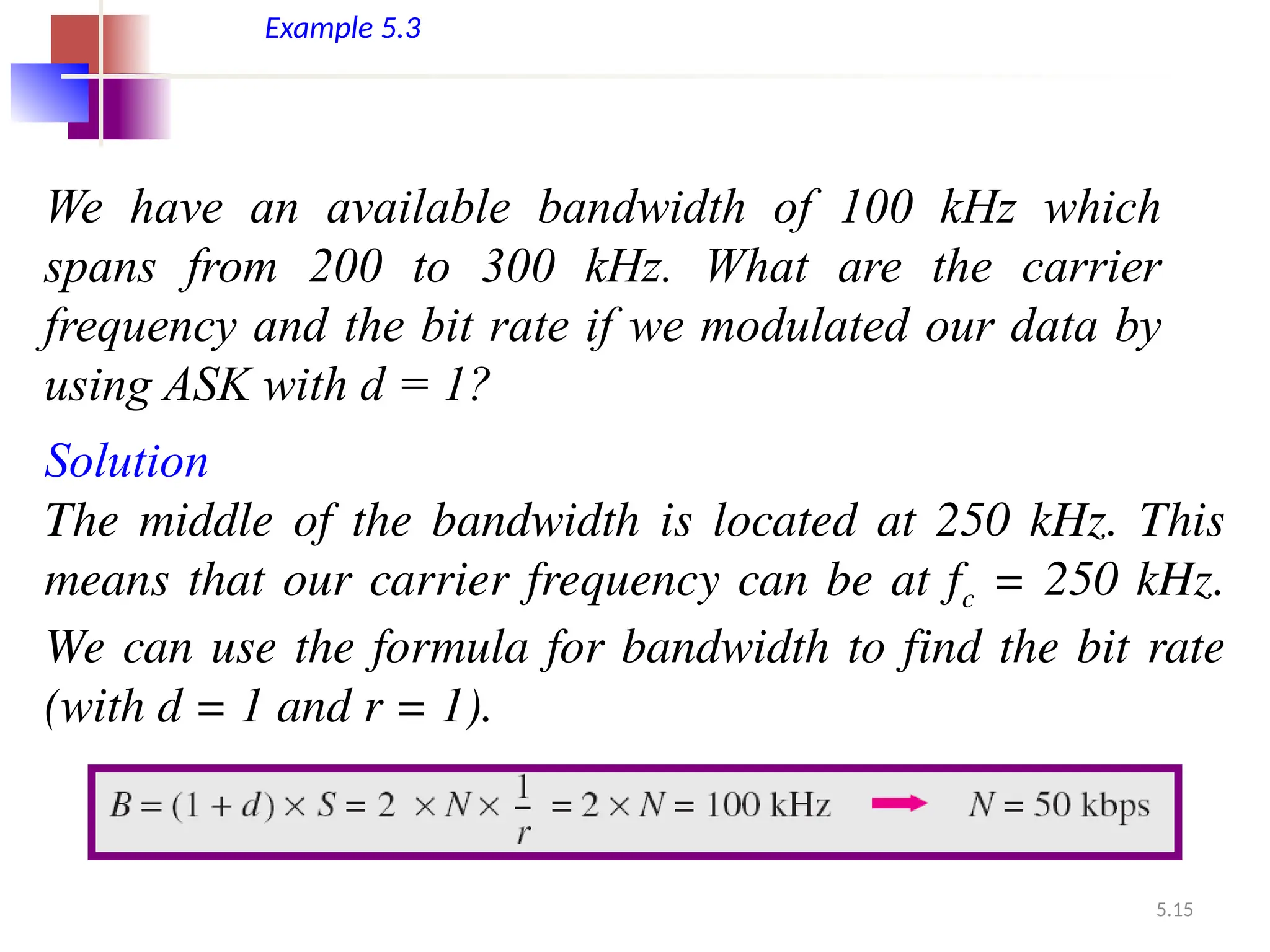
Example 5.3
We havean available bandwidth of 100 kHz which
spans from 200 to 300 kHz. What are the carrier
frequency and the bit rate if we modulated our data by
using ASK with d = 1?
Solution
The middle of the bandwidth is located at 250 kHz. This
means that our carrier frequency can be at fc = 250 kHz.
We can use the formula for bandwidth to find the bit rate
(with d = 1 and r = 1).
16.
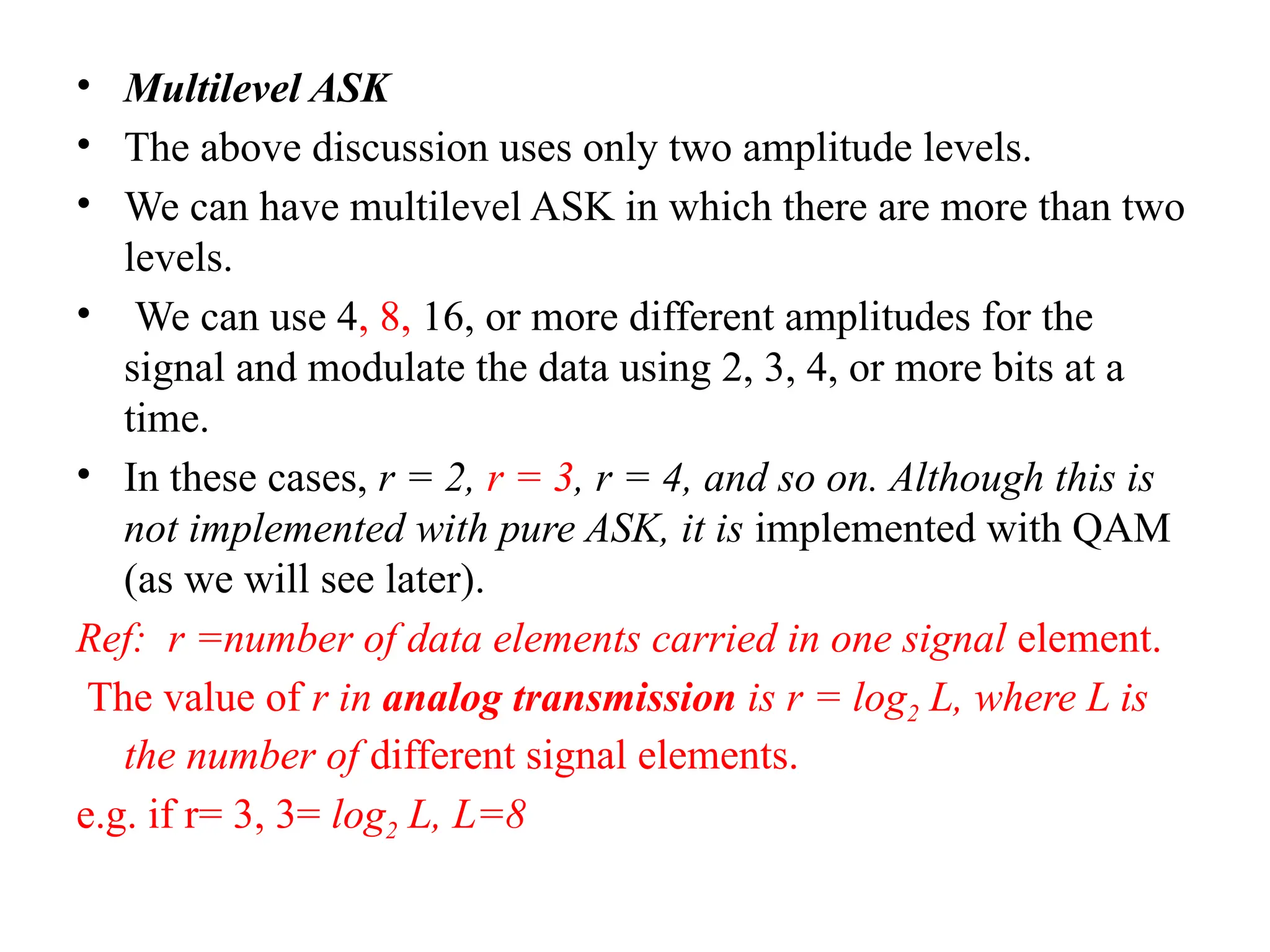
• Multilevel ASK
•The above discussion uses only two amplitude levels.
• We can have multilevel ASK in which there are more than two
levels.
• We can use 4, 8, 16, or more different amplitudes for the
signal and modulate the data using 2, 3, 4, or more bits at a
time.
• In these cases, r = 2, r = 3, r = 4, and so on. Although this is
not implemented with pure ASK, it is implemented with QAM
(as we will see later).
Ref: r =number of data elements carried in one signal element.
The value of r in analog transmission is r = log2 L, where L is
the number of different signal elements.
e.g. if r= 3, 3= log2 L, L=8
17.
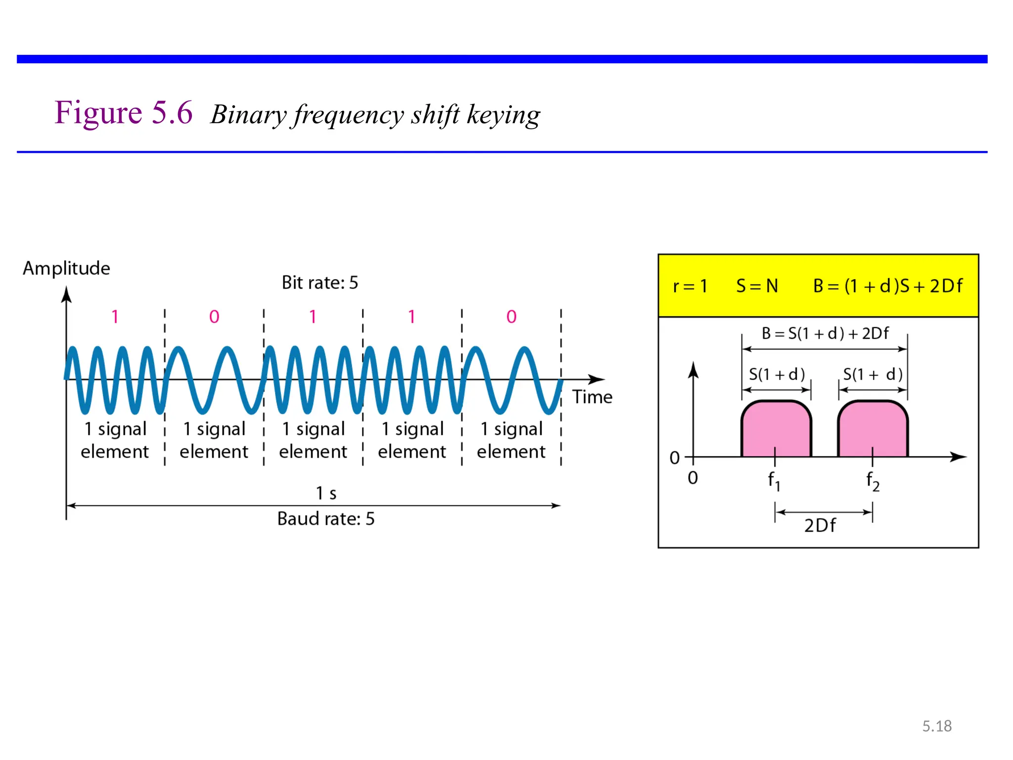
3.1.3 Frequency ShiftKeying
• Here frequency of the carrier signal is varied to represent
data.
• The frequency of the modulated signal is constant for the
duration of one signal element, but changes for the next signal
element if the data element changes.
• Both peak amplitude and phase remain constant for all signal
elements.
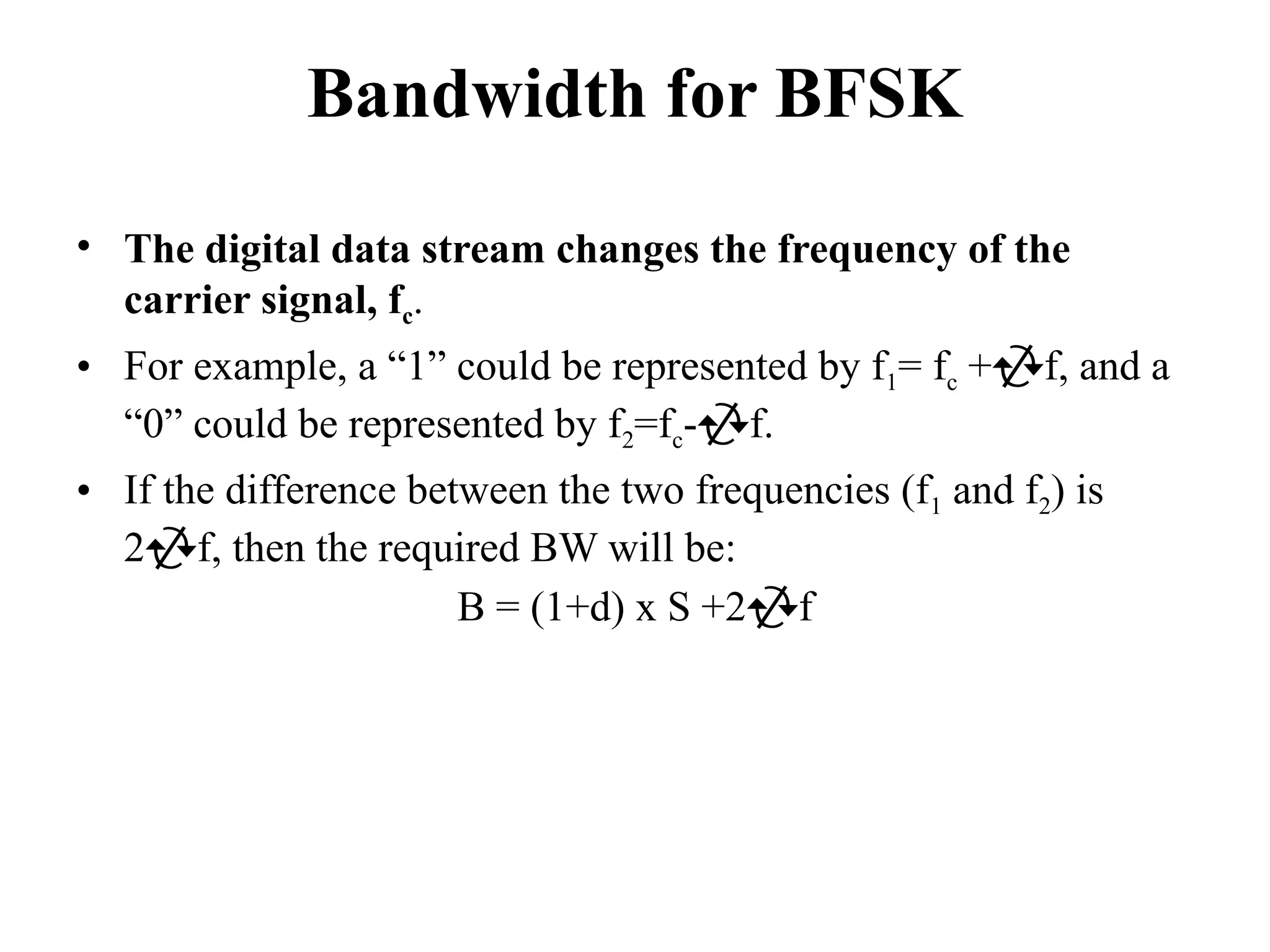
Bandwidth for BFSK
•The digital data stream changes the frequency of the
carrier signal, fc.
• For example, a “1” could be represented by f1= fc +f, and a
“0” could be represented by f2=fc-f.
• If the difference between the two frequencies (f1 and f2) is
2f, then the required BW will be:
B = (1+d) x S +2f
20.
5.20
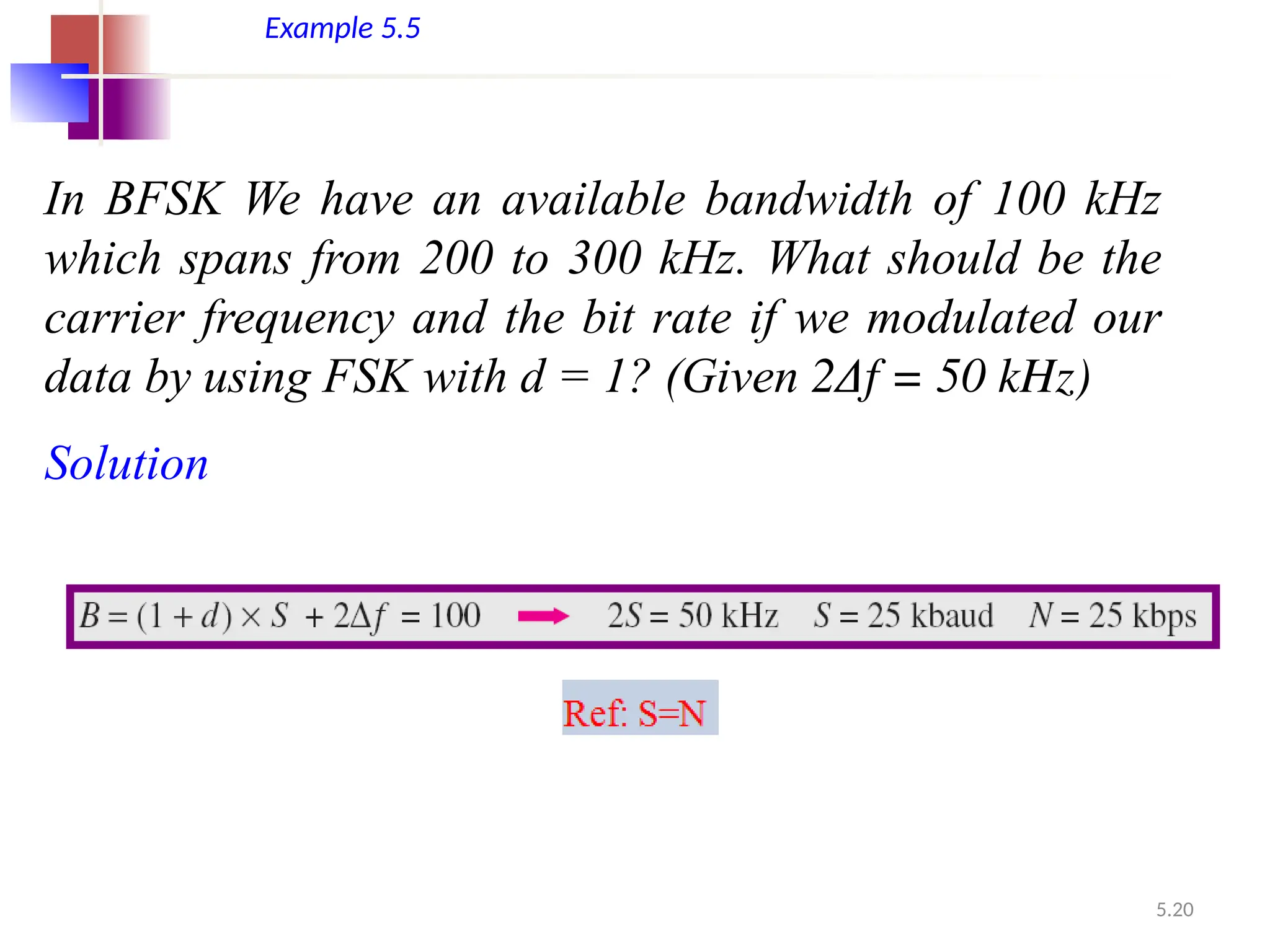
Example 5.5
In BFSKWe have an available bandwidth of 100 kHz
which spans from 200 to 300 kHz. What should be the
carrier frequency and the bit rate if we modulated our
data by using FSK with d = 1? (Given 2Δf = 50 kHz)
Solution
21.
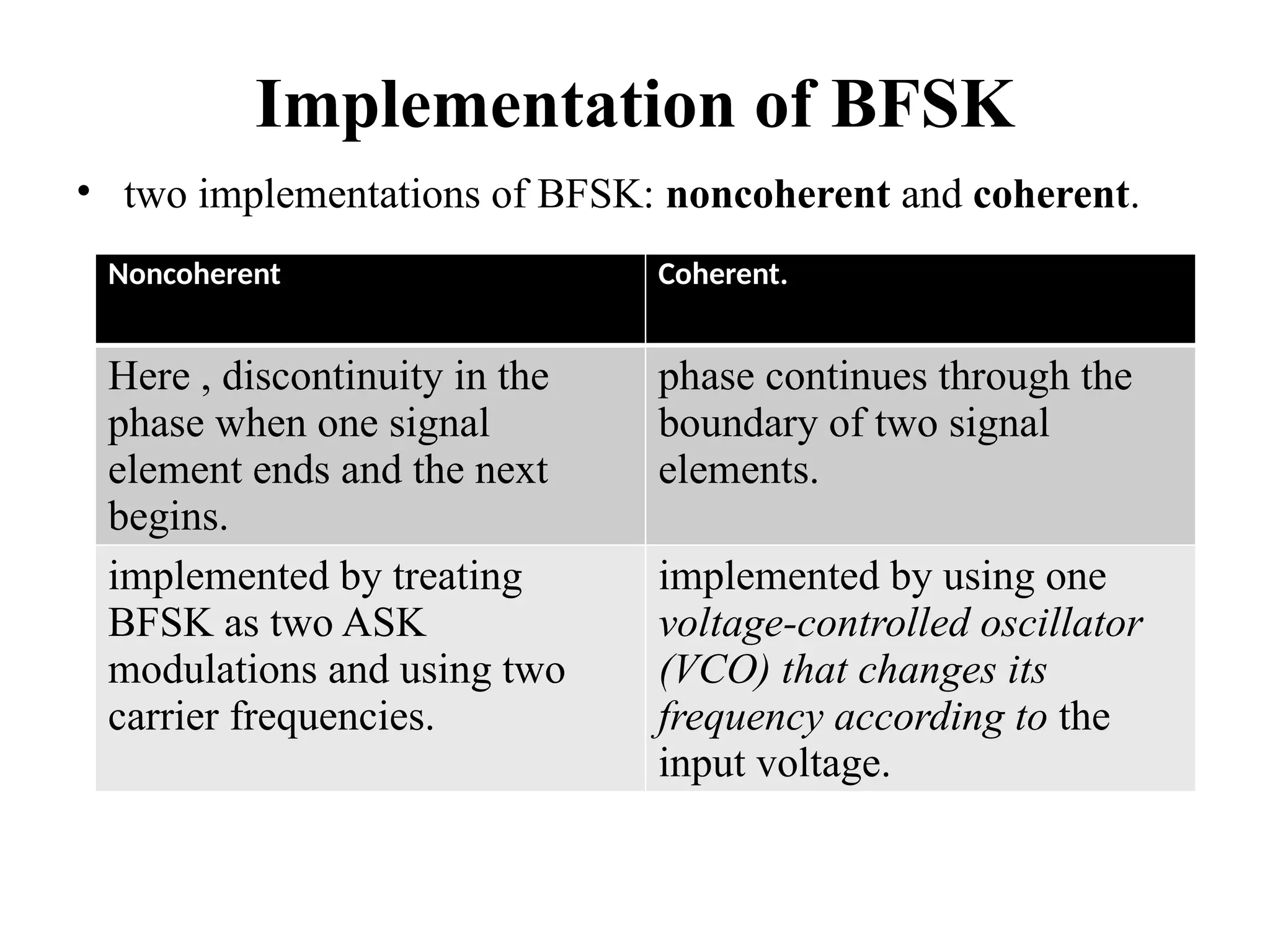
Implementation of BFSK
•two implementations of BFSK: noncoherent and coherent.
Noncoherent Coherent.
Here , discontinuity in the
phase when one signal
element ends and the next
begins.
phase continues through the
boundary of two signal
elements.
implemented by treating
BFSK as two ASK
modulations and using two
carrier frequencies.
implemented by using one
voltage-controlled oscillator
(VCO) that changes its
frequency according to the
input voltage.
22.
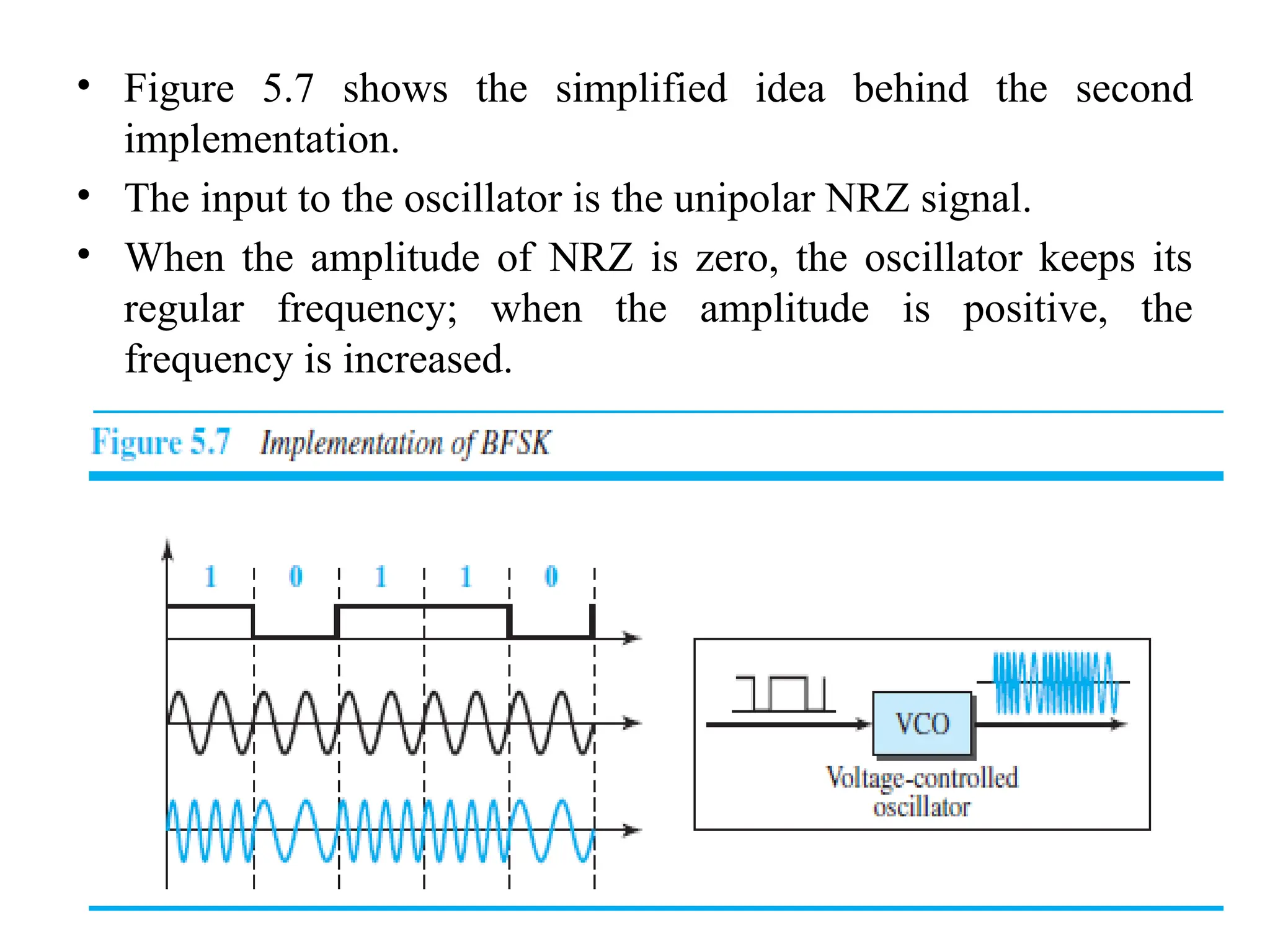
• Figure 5.7shows the simplified idea behind the second
implementation.
• The input to the oscillator is the unipolar NRZ signal.
• When the amplitude of NRZ is zero, the oscillator keeps its
regular frequency; when the amplitude is positive, the
frequency is increased.
23.
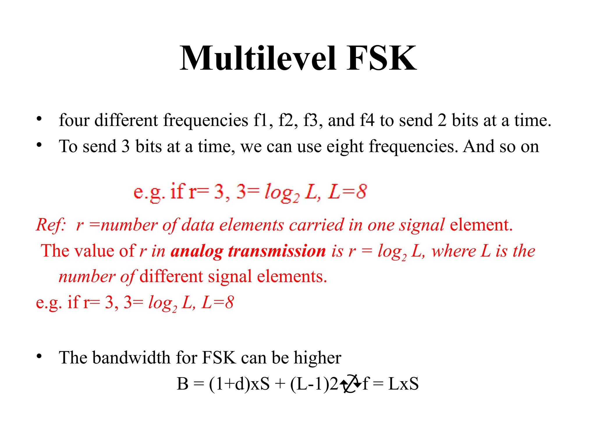
Multilevel FSK
• fourdifferent frequencies f1, f2, f3, and f4 to send 2 bits at a time.
• To send 3 bits at a time, we can use eight frequencies. And so on
Ref: r =number of data elements carried in one signal element.
The value of r in analog transmission is r = log2 L, where L is the
number of different signal elements.
e.g. if r= 3, 3= log2 L, L=8
• The bandwidth for FSK can be higher
B = (1+d)xS + (L-1)2f = LxS
24.
5.1.4 Phase ShiftKeying
• Here, the phase of the carrier is varied to represent two or
more different signal elements.
• Both peak amplitude and frequency remain constant as the
phase changes.
• Today, PSK is more common than ASK or FSK.
• However, we will see shortly that QAM, which combines ASK
and PSK, is the dominant method of digital-to-analog
modulation.
25.
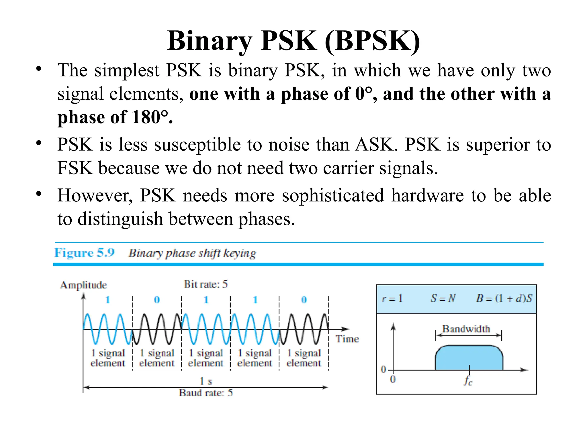
Binary PSK (BPSK)
•The simplest PSK is binary PSK, in which we have only two
signal elements, one with a phase of 0°, and the other with a
phase of 180°.
• PSK is less susceptible to noise than ASK. PSK is superior to
FSK because we do not need two carrier signals.
• However, PSK needs more sophisticated hardware to be able
to distinguish between phases.
26.
Bandwidth
• Figure 5.9also shows the bandwidth for BPSK.
• The bandwidth is the same as that for binary ASK, but less
than that for BFSK.
• No bandwidth is wasted for separating two carrier signals.
27.
Implementation
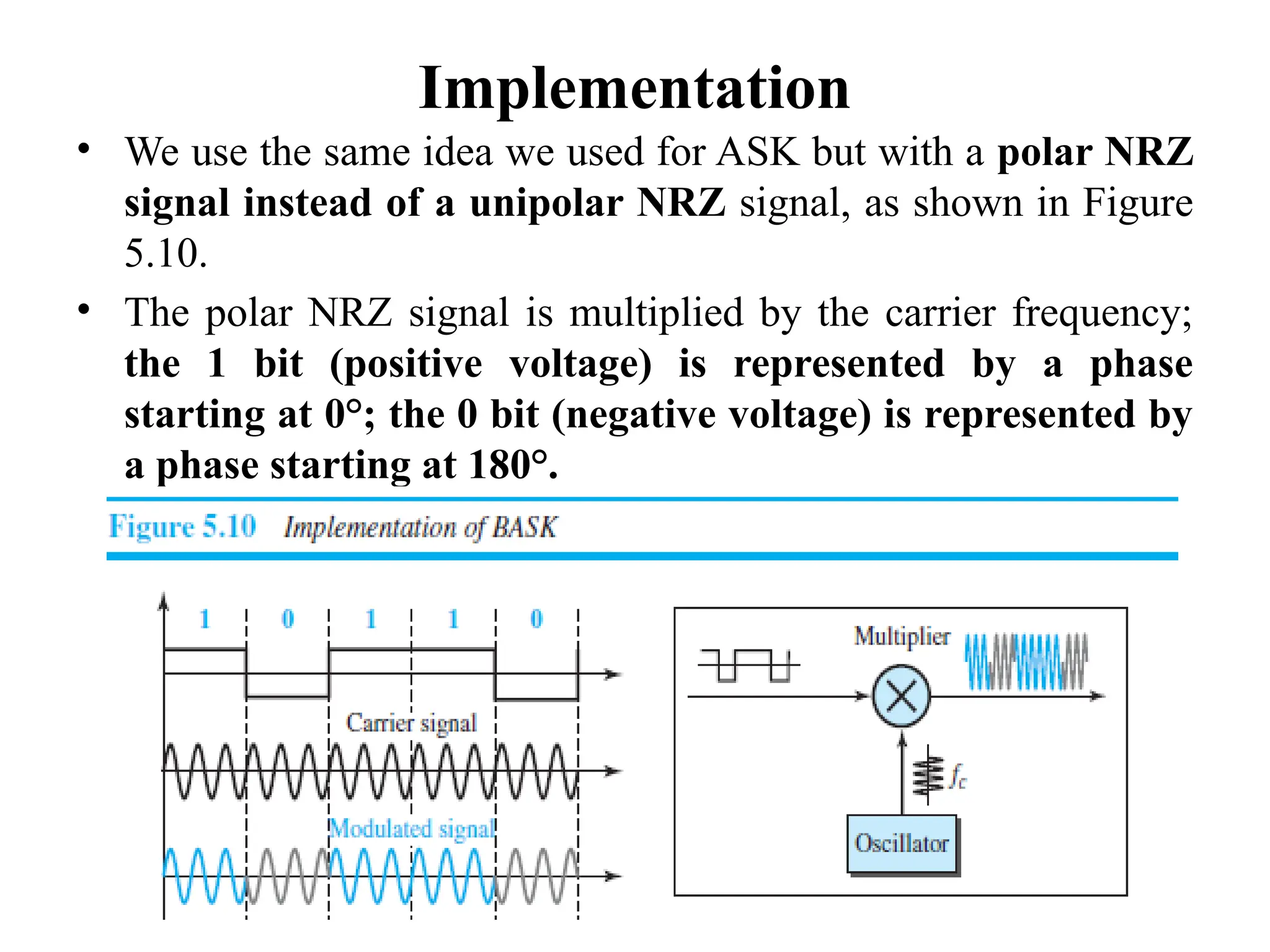
• We usethe same idea we used for ASK but with a polar NRZ
signal instead of a unipolar NRZ signal, as shown in Figure
5.10.
• The polar NRZ signal is multiplied by the carrier frequency;
the 1 bit (positive voltage) is represented by a phase
starting at 0°; the 0 bit (negative voltage) is represented by
a phase starting at 180°.
28.
Quadrature PSK (QPSK)
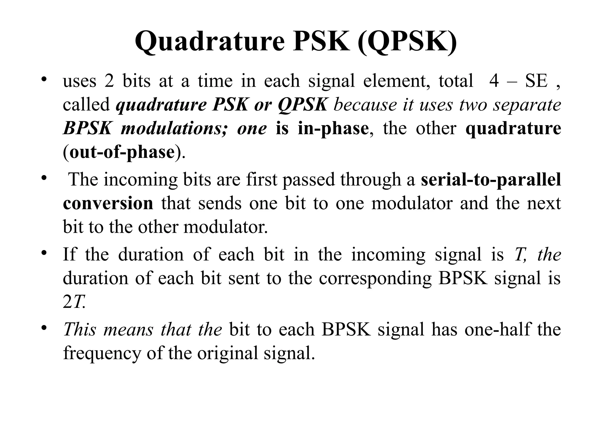
•uses 2 bits at a time in each signal element, total 4 – SE ,
called quadrature PSK or QPSK because it uses two separate
BPSK modulations; one is in-phase, the other quadrature
(out-of-phase).
• The incoming bits are first passed through a serial-to-parallel
conversion that sends one bit to one modulator and the next
bit to the other modulator.
• If the duration of each bit in the incoming signal is T, the
duration of each bit sent to the corresponding BPSK signal is
2T.
• This means that the bit to each BPSK signal has one-half the
frequency of the original signal.
29.
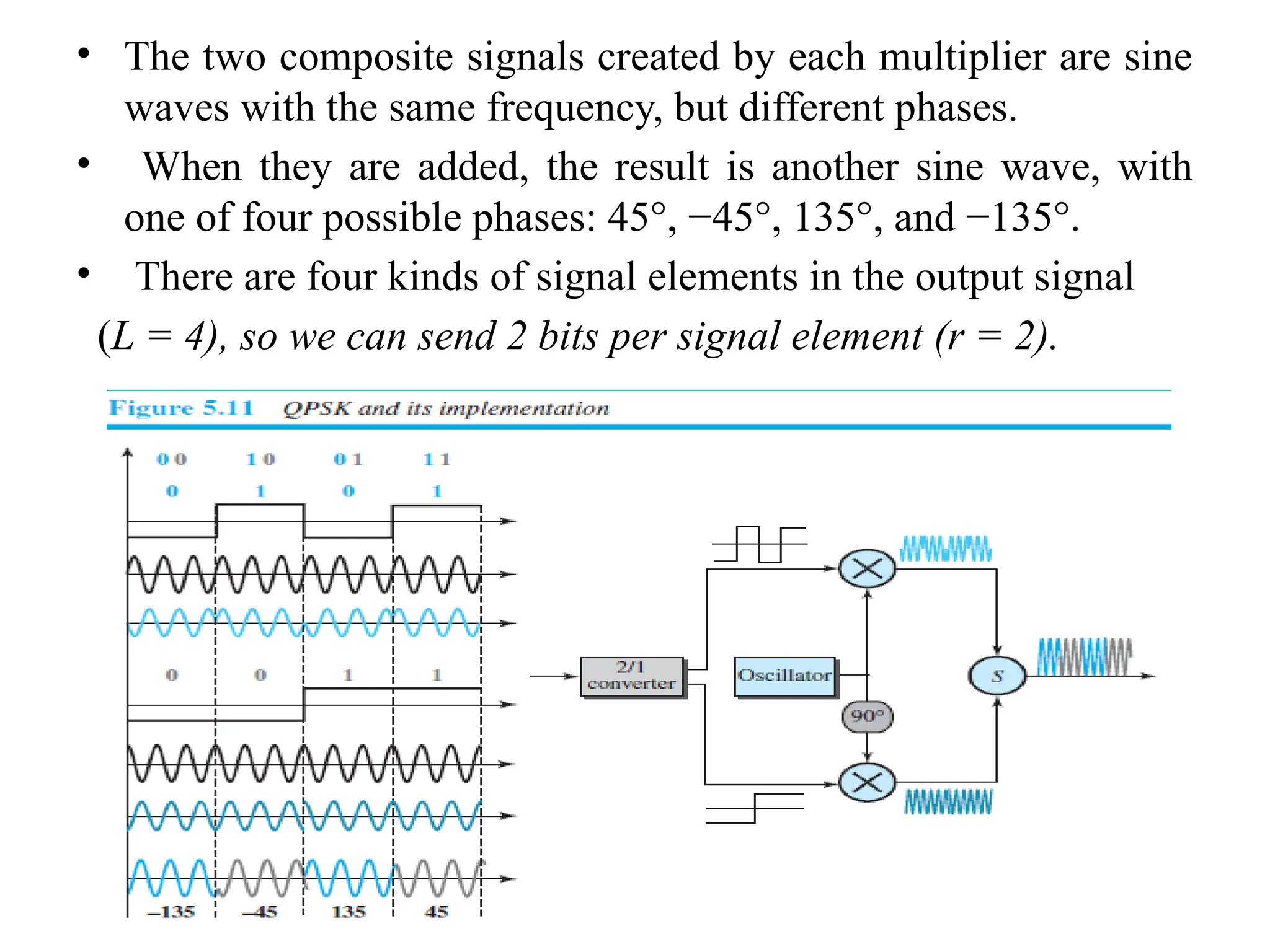
• The twocomposite signals created by each multiplier are sine
waves with the same frequency, but different phases.
• When they are added, the result is another sine wave, with
one of four possible phases: 45°, −45°, 135°, and −135°.
• There are four kinds of signal elements in the output signal
(L = 4), so we can send 2 bits per signal element (r = 2).
30.
5.30
Quadrature PSK
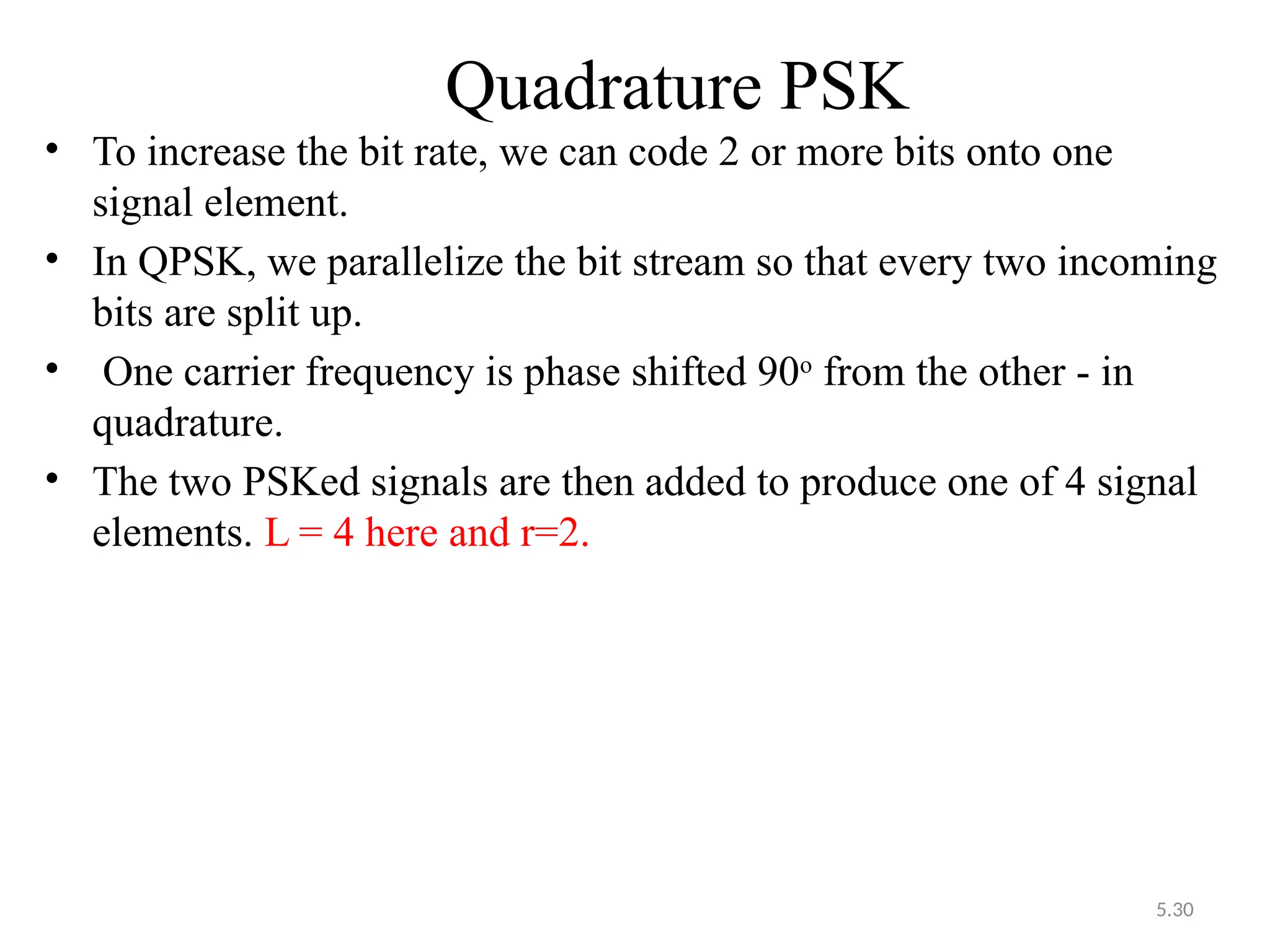
• Toincrease the bit rate, we can code 2 or more bits onto one
signal element.
• In QPSK, we parallelize the bit stream so that every two incoming
bits are split up.
• One carrier frequency is phase shifted 90o
from the other - in
quadrature.
• The two PSKed signals are then added to produce one of 4 signal
elements. L = 4 here and r=2.
31.
5.31
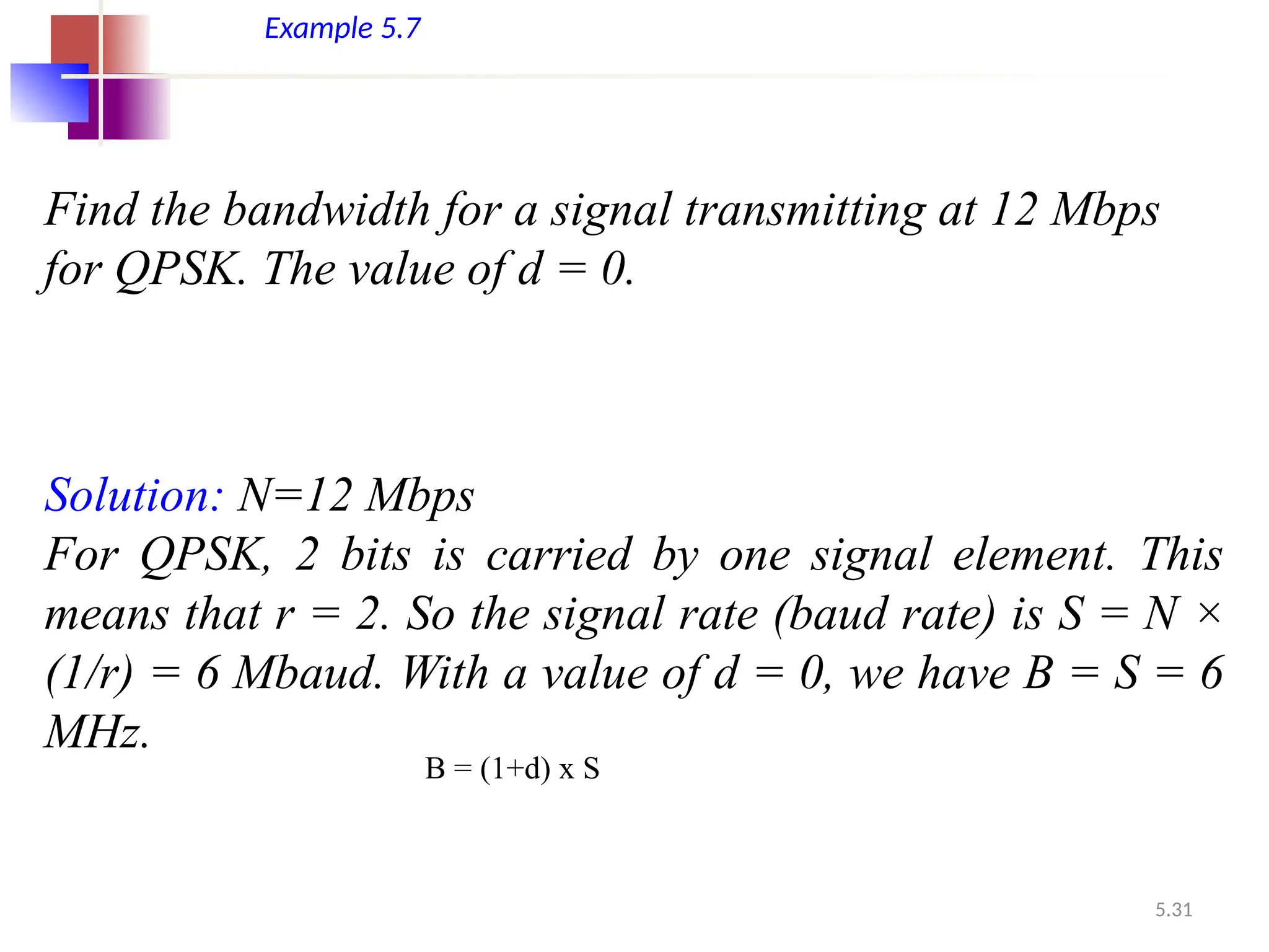
Example 5.7
Find thebandwidth for a signal transmitting at 12 Mbps
for QPSK. The value of d = 0.
Solution: N=12 Mbps
For QPSK, 2 bits is carried by one signal element. This
means that r = 2. So the signal rate (baud rate) is S = N ×
(1/r) = 6 Mbaud. With a value of d = 0, we have B = S = 6
MHz.
B = (1+d) x S
32.
Constellation Diagrams
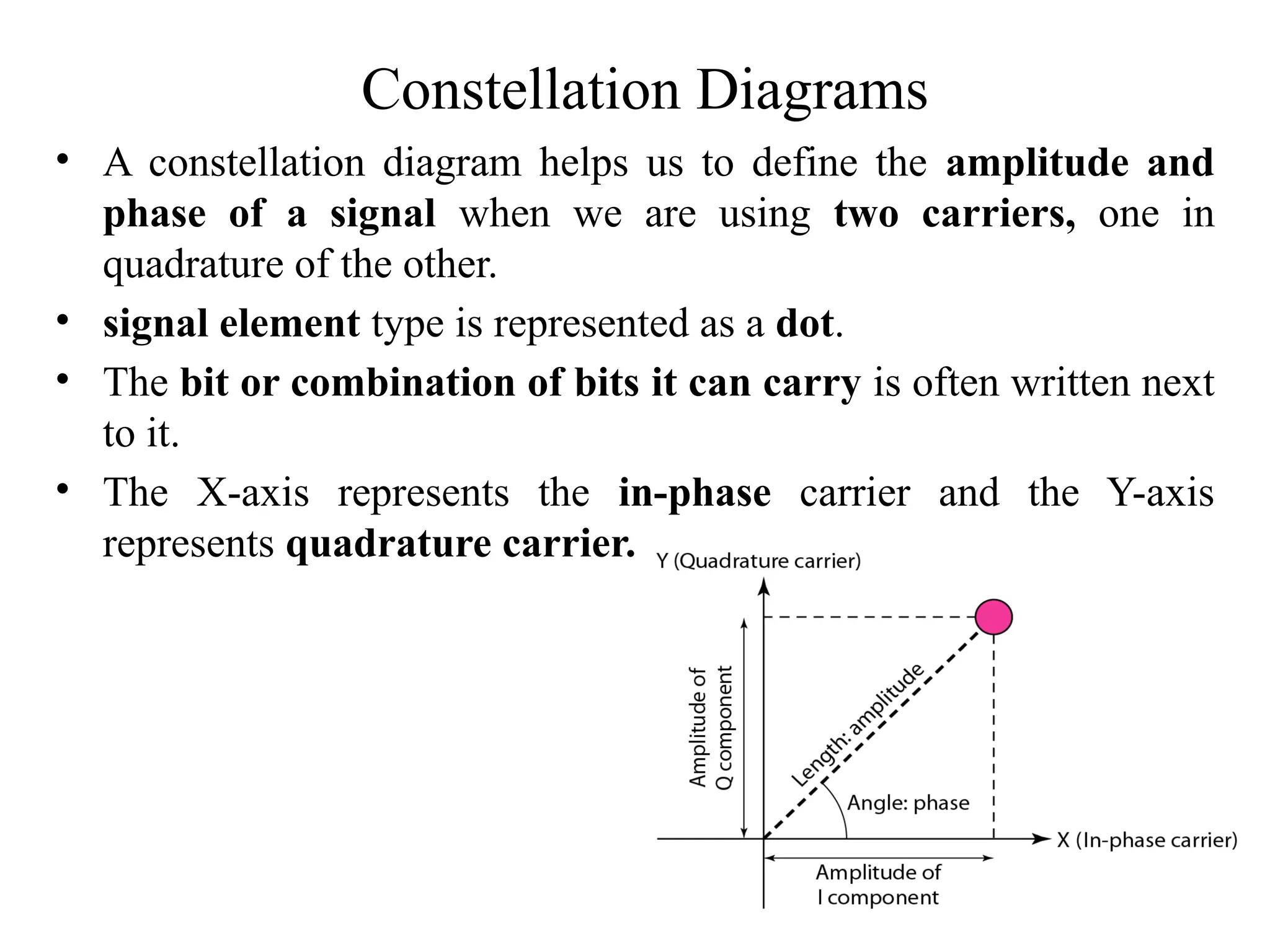
• Aconstellation diagram helps us to define the amplitude and
phase of a signal when we are using two carriers, one in
quadrature of the other.
• signal element type is represented as a dot.
• The bit or combination of bits it can carry is often written next
to it.
• The X-axis represents the in-phase carrier and the Y-axis
represents quadrature carrier.
5.34
Constellation Diagrams
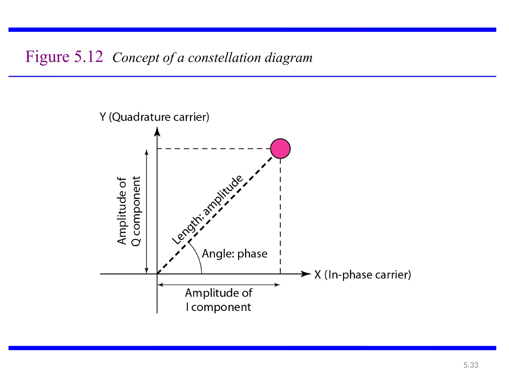
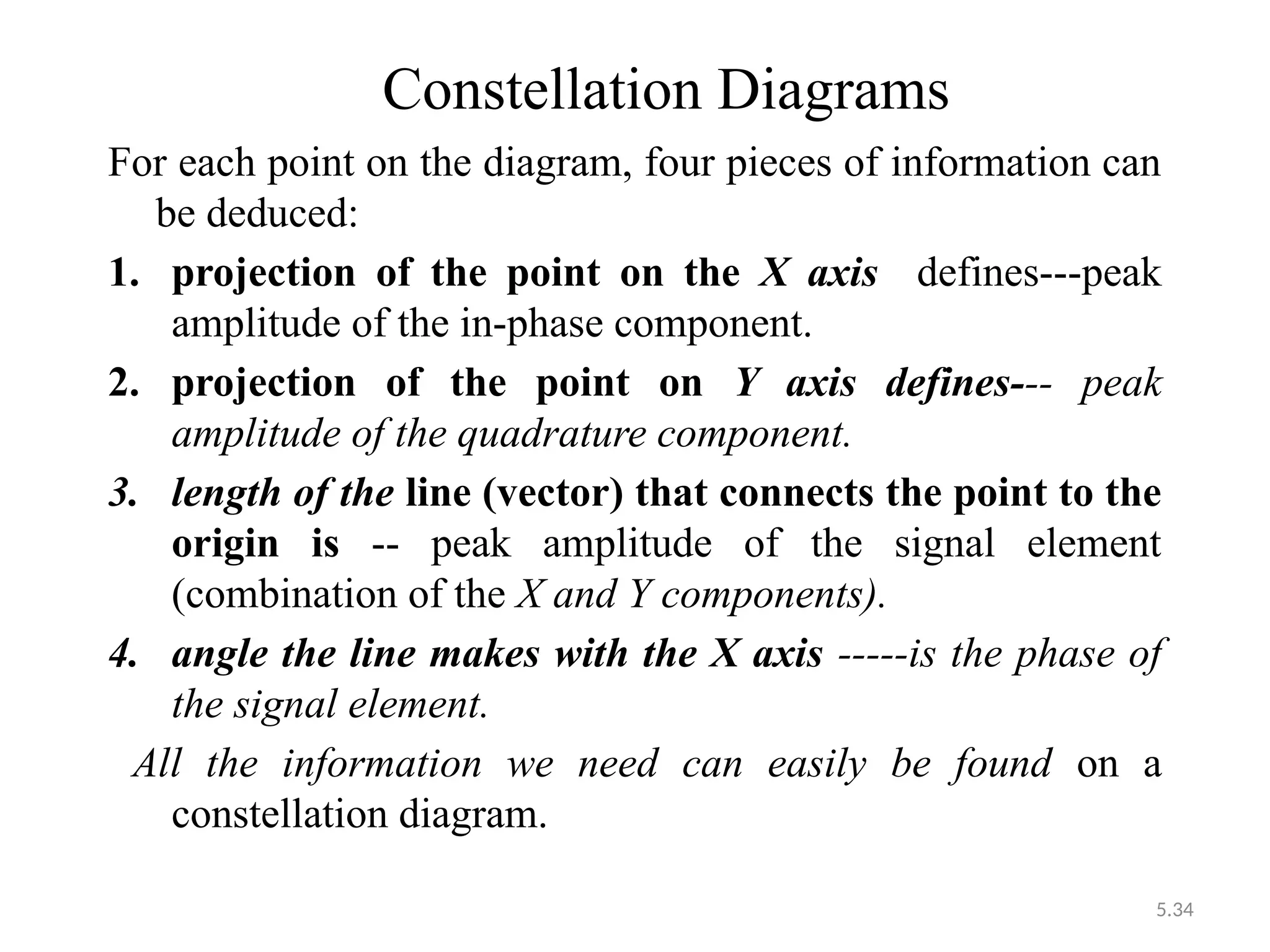
For eachpoint on the diagram, four pieces of information can
be deduced:
1. projection of the point on the X axis defines---peak
amplitude of the in-phase component.
2. projection of the point on Y axis defines--- peak
amplitude of the quadrature component.
3. length of the line (vector) that connects the point to the
origin is -- peak amplitude of the signal element
(combination of the X and Y components).
4. angle the line makes with the X axis -----is the phase of
the signal element.
All the information we need can easily be found on a
constellation diagram.
35.
5.35
Example 5.8
Show theconstellation diagrams for an ASK (OOK),
BPSK, and QPSK signals.
Solution
Figure 5.13 shows the three constellation diagrams.—next
slide
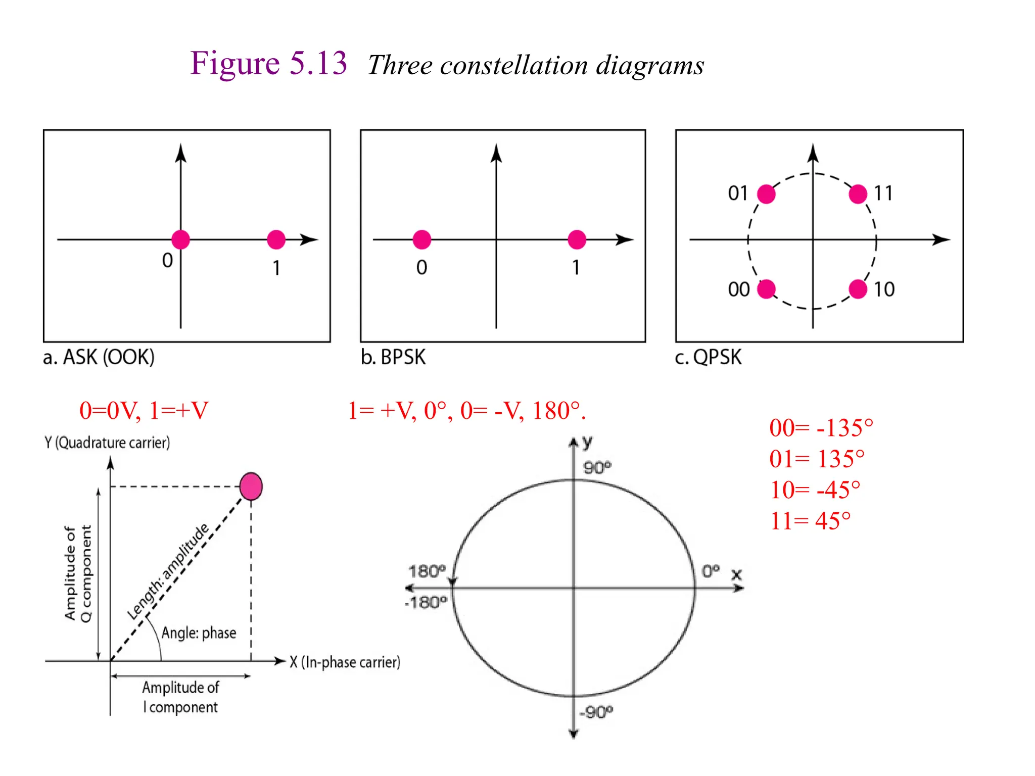
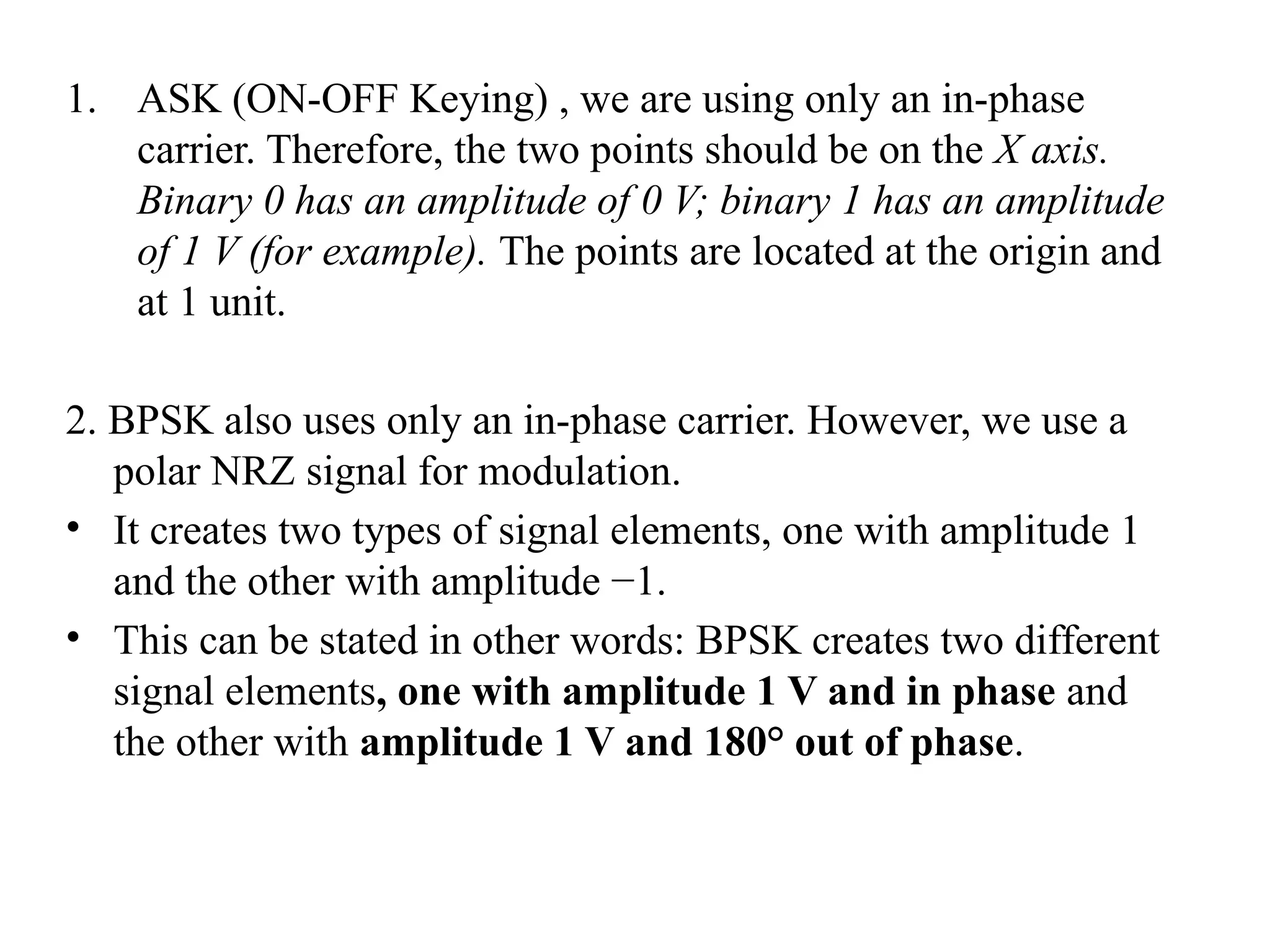
1. ASK (ON-OFFKeying) , we are using only an in-phase
carrier. Therefore, the two points should be on the X axis.
Binary 0 has an amplitude of 0 V; binary 1 has an amplitude
of 1 V (for example). The points are located at the origin and
at 1 unit.
2. BPSK also uses only an in-phase carrier. However, we use a
polar NRZ signal for modulation.
• It creates two types of signal elements, one with amplitude 1
and the other with amplitude −1.
• This can be stated in other words: BPSK creates two different
signal elements, one with amplitude 1 V and in phase and
the other with amplitude 1 V and 180° out of phase.
39.
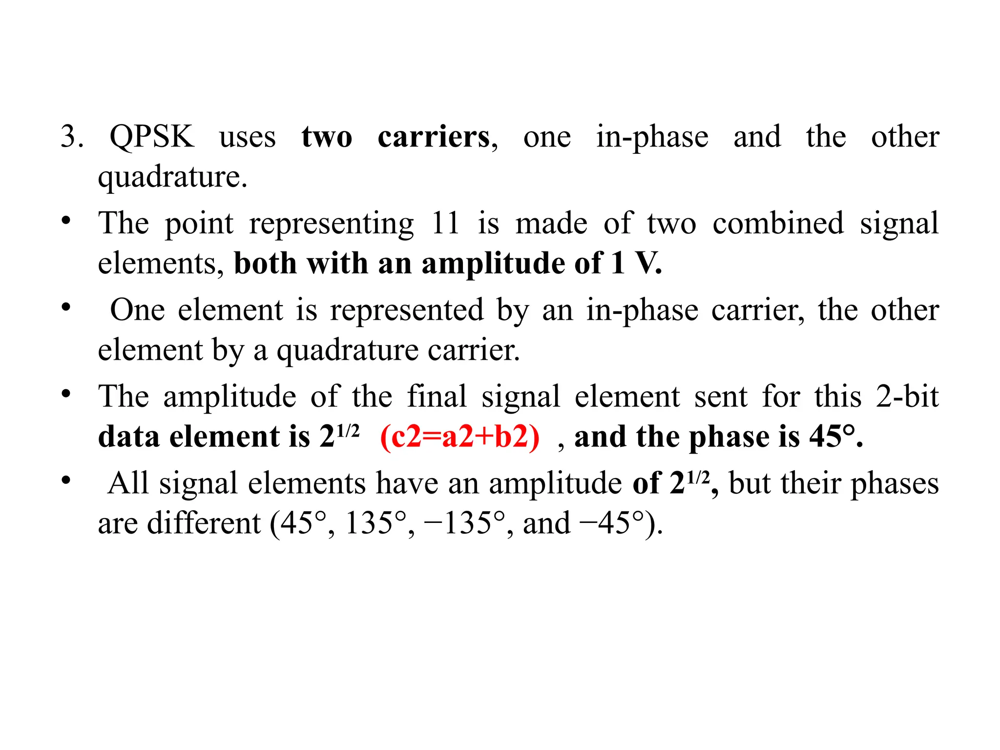
3. QPSK usestwo carriers, one in-phase and the other
quadrature.
• The point representing 11 is made of two combined signal
elements, both with an amplitude of 1 V.
• One element is represented by an in-phase carrier, the other
element by a quadrature carrier.
• The amplitude of the final signal element sent for this 2-bit
data element is 21/2
(c2=a2+b2) , and the phase is 45°.
• All signal elements have an amplitude of 21/2
, but their phases
are different (45°, 135°, −135°, and −45°).
40.
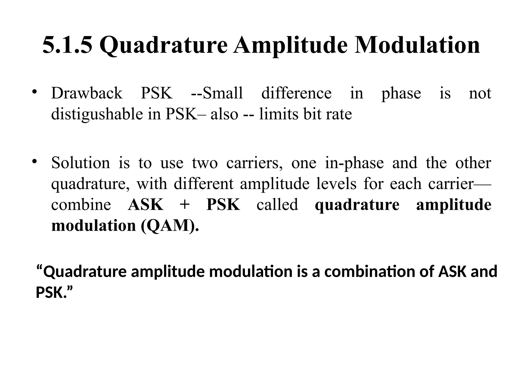
5.1.5 Quadrature AmplitudeModulation
• Drawback PSK --Small difference in phase is not
distigushable in PSK– also -- limits bit rate
• Solution is to use two carriers, one in-phase and the other
quadrature, with different amplitude levels for each carrier—
combine ASK + PSK called quadrature amplitude
modulation (QAM).
“Quadrature amplitude modulation is a combination of ASK and
PSK.”
41.
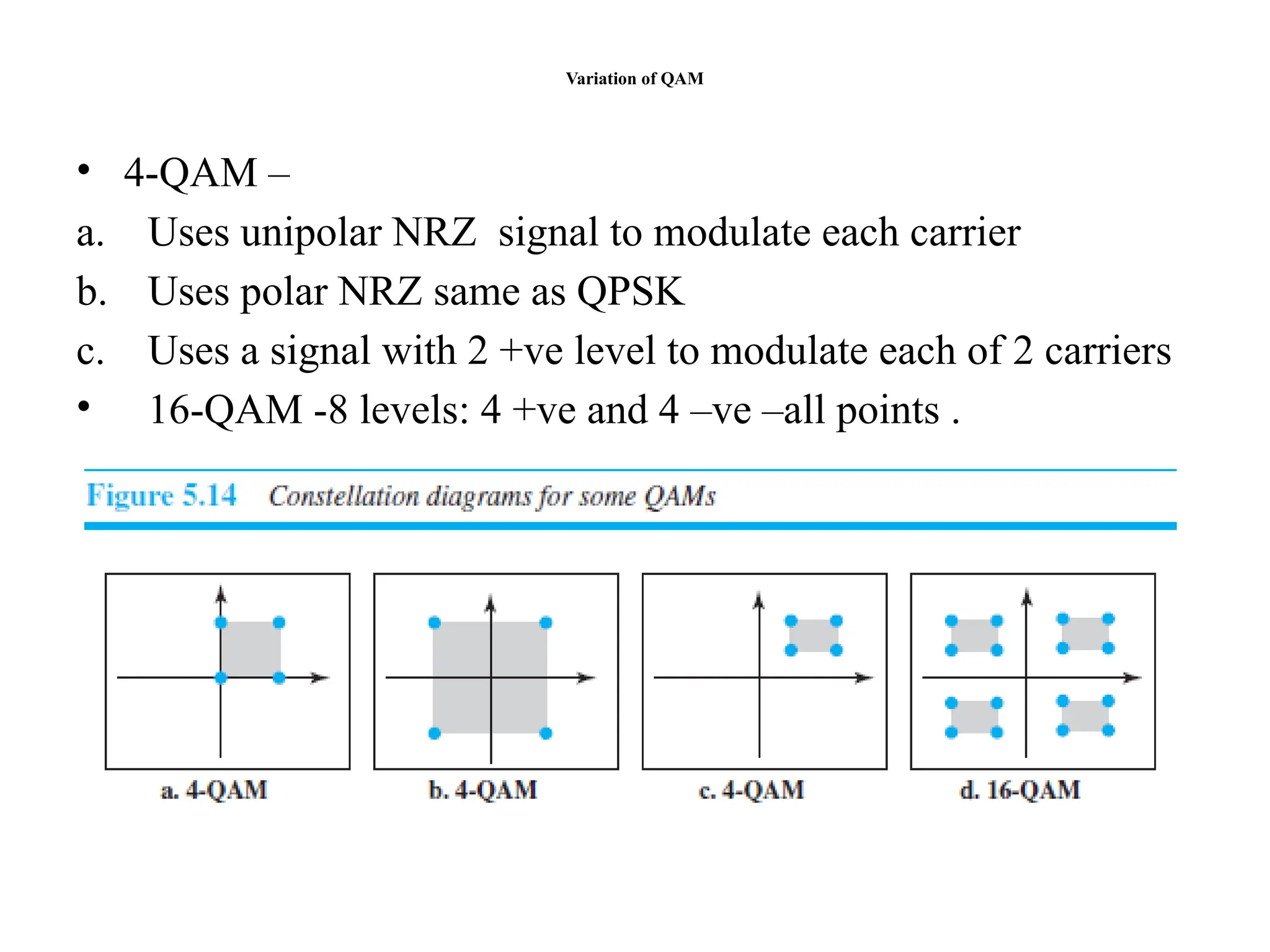
Variation of QAM
•4-QAM –
a. Uses unipolar NRZ signal to modulate each carrier
b. Uses polar NRZ same as QPSK
c. Uses a signal with 2 +ve level to modulate each of 2 carriers
• 16-QAM -8 levels: 4 +ve and 4 –ve –all points .
42.
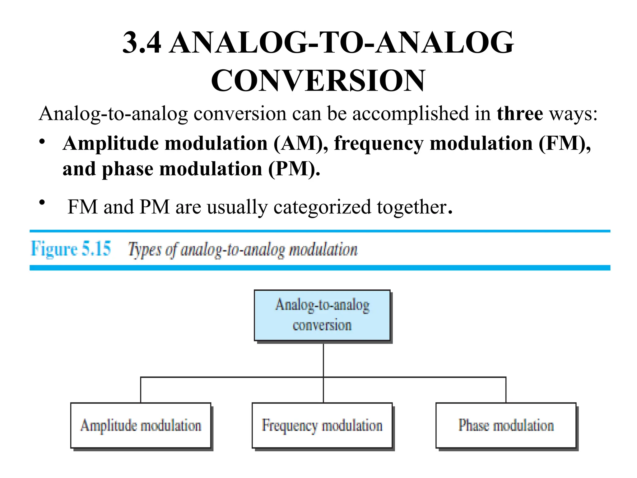
3.4 ANALOG-TO-ANALOG CONVERSION
•Also called analog modulation, is the representation of
analog information by an analog signal.
• why we need to modulate an analog signal;?it is already
analog.
• Modulation is needed if the medium is bandpass in nature or
if only a bandpass channel is available to us.
• An example is radio.
• The government assigns narrow bandwidth to each radio
station. (e.g. 91.7 FM – means radio station broadcast on FM
frequency 91.7 MHz) 93.5 red fm etc..
• The analog signal produced by each station is a low-pass
signal, all in the same range.
• To be able to listen to different stations, the low-pass signals
need to be shifted, each to a different range.
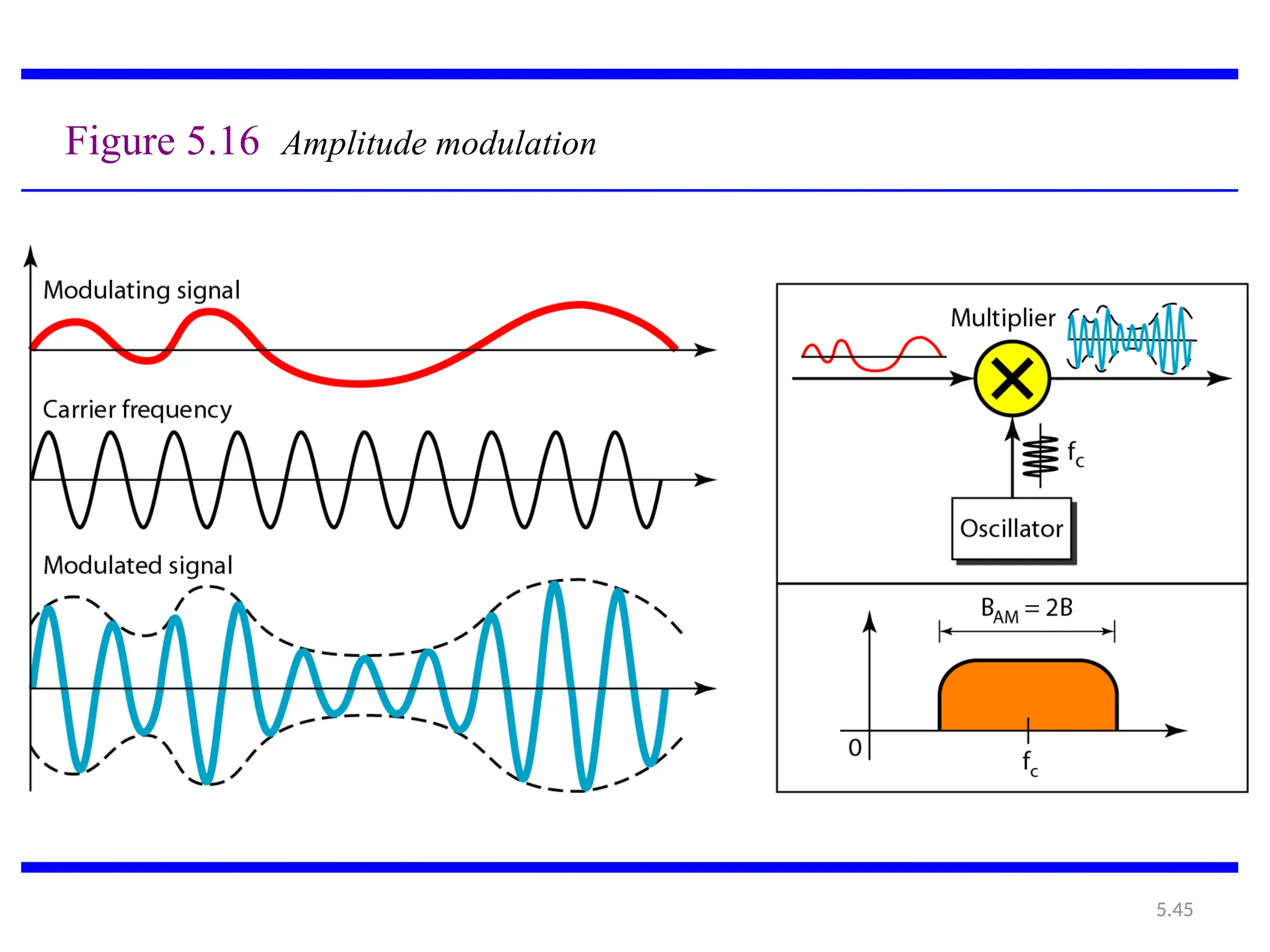
5.2.1 Amplitude Modulation(AM)
• In AM transmission, the carrier signal is modulated so that its
amplitude varies with the changing amplitudes of the
modulating signal.
• The frequency and phase of the carrier remain the same; only
the amplitude changes to follow variations in the information.
• AM is normally implemented by using a simple multiplier
because the amplitude of the carrier signal needs to be
changed according to the amplitude of the modulating signal.
Note : carrier frequency will take shape of modulating signal.
• In another way , amplitude of carrier signal is modulated as
per the changing amplitudes of the modulating signal.
AM Bandwidth
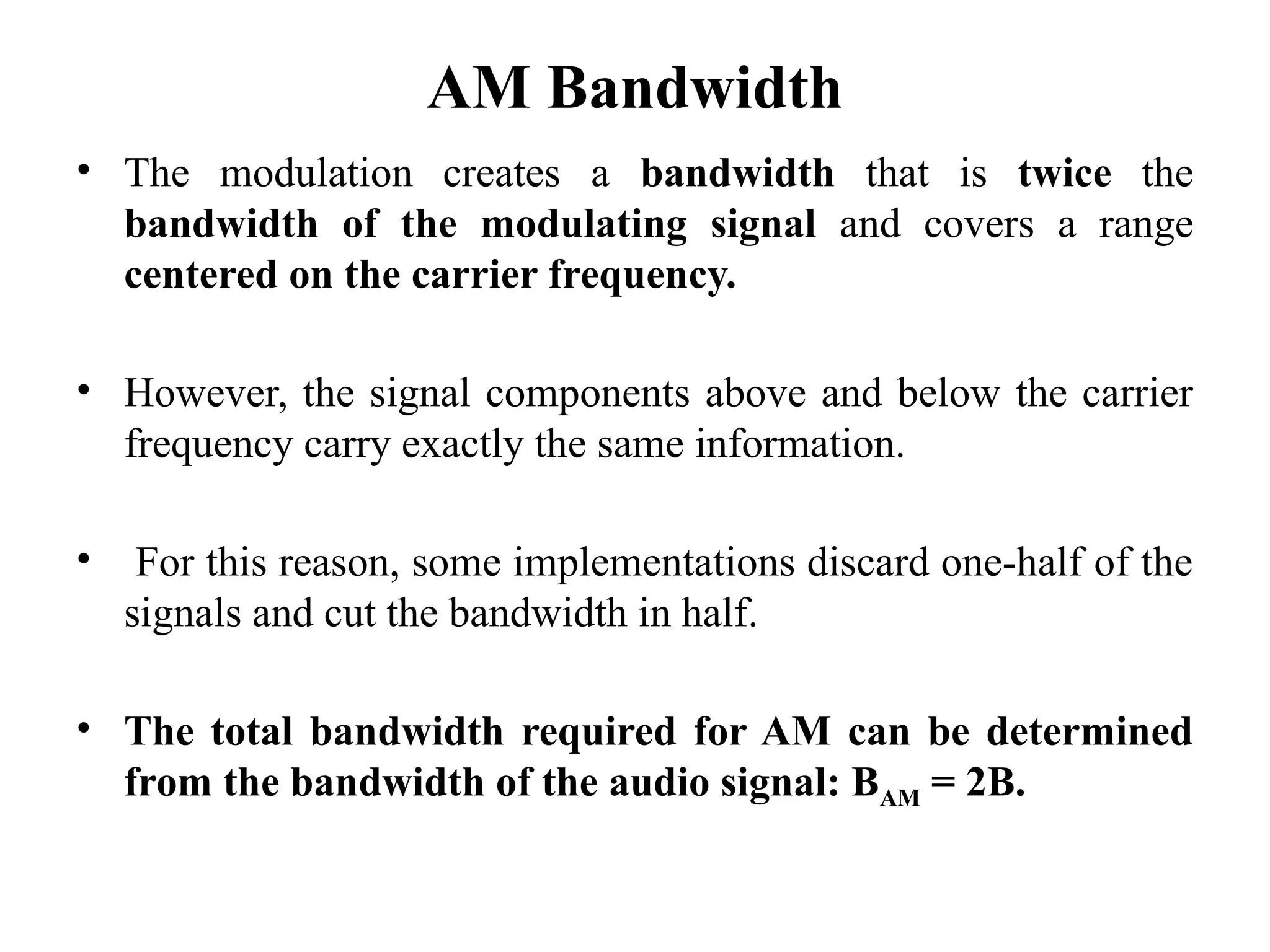
• Themodulation creates a bandwidth that is twice the
bandwidth of the modulating signal and covers a range
centered on the carrier frequency.
• However, the signal components above and below the carrier
frequency carry exactly the same information.
• For this reason, some implementations discard one-half of the
signals and cut the bandwidth in half.
• The total bandwidth required for AM can be determined
from the bandwidth of the audio signal: BAM = 2B.
47.
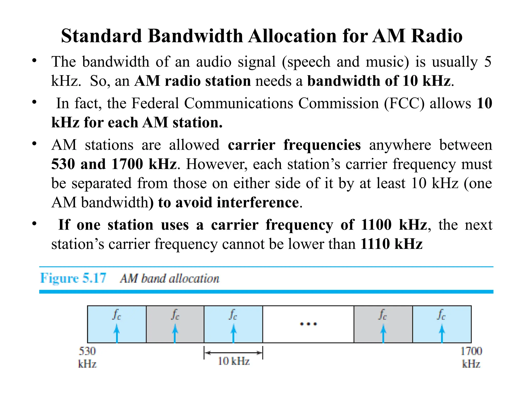
Standard Bandwidth Allocationfor AM Radio
• The bandwidth of an audio signal (speech and music) is usually 5
kHz. So, an AM radio station needs a bandwidth of 10 kHz.
• In fact, the Federal Communications Commission (FCC) allows 10
kHz for each AM station.
• AM stations are allowed carrier frequencies anywhere between
530 and 1700 kHz. However, each station’s carrier frequency must
be separated from those on either side of it by at least 10 kHz (one
AM bandwidth) to avoid interference.
• If one station uses a carrier frequency of 1100 kHz, the next
station’s carrier frequency cannot be lower than 1110 kHz
48.
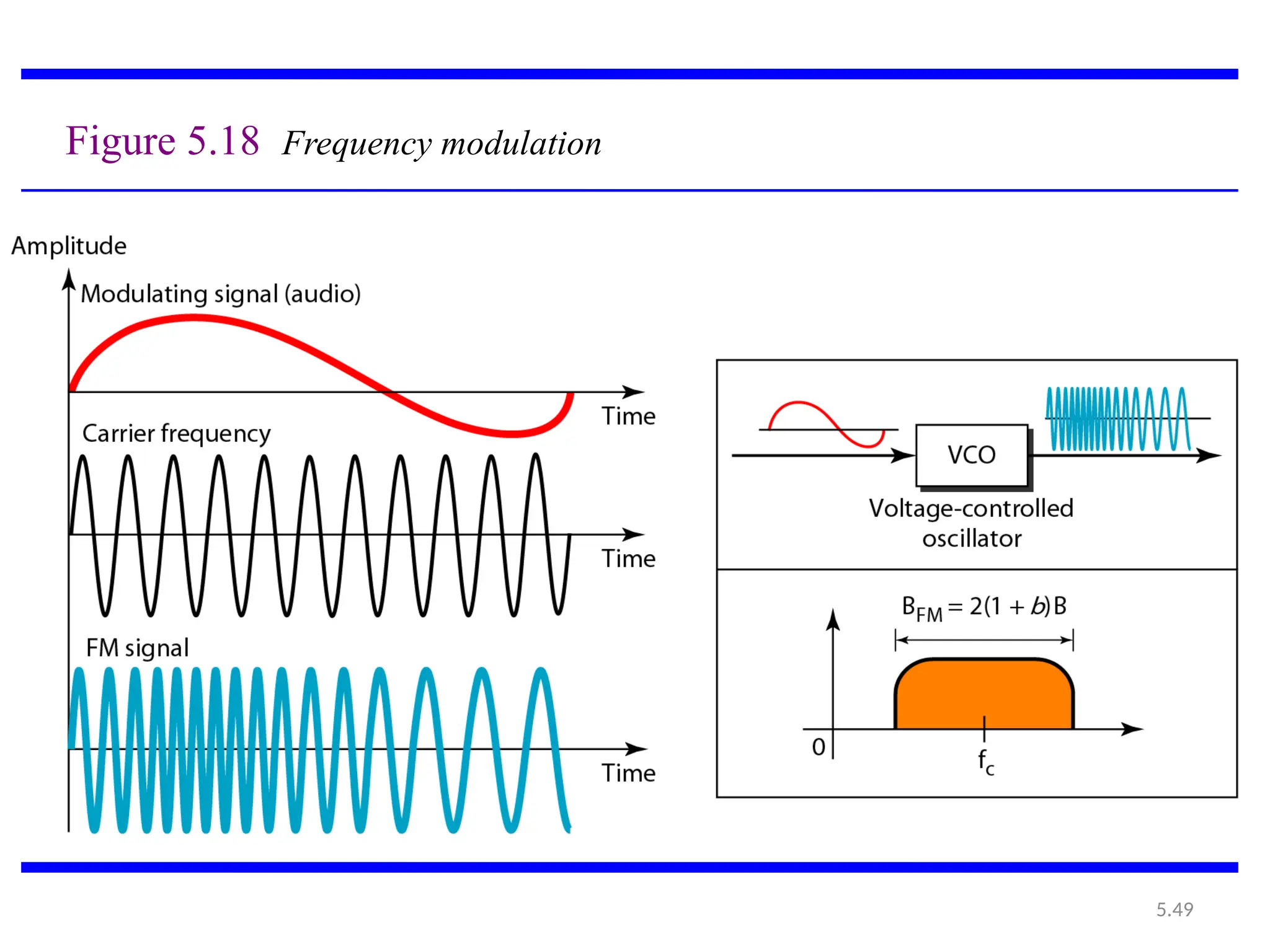
5.2.2 Frequency Modulation(FM)
• In FM transmission, frequency of the carrier signal is
modulated to follow the changing voltage level (amplitude) of
the modulating signal.
• The peak amplitude and phase of the carrier signal remain
constant, but as the amplitude of the information signal
changes, the frequency of the carrier changes
correspondingly.
• FM is normally implemented by using a voltage-controlled
oscillator as with FSK.
• The frequency of the oscillator changes according to the
input voltage which is the amplitude of the modulating
signal.
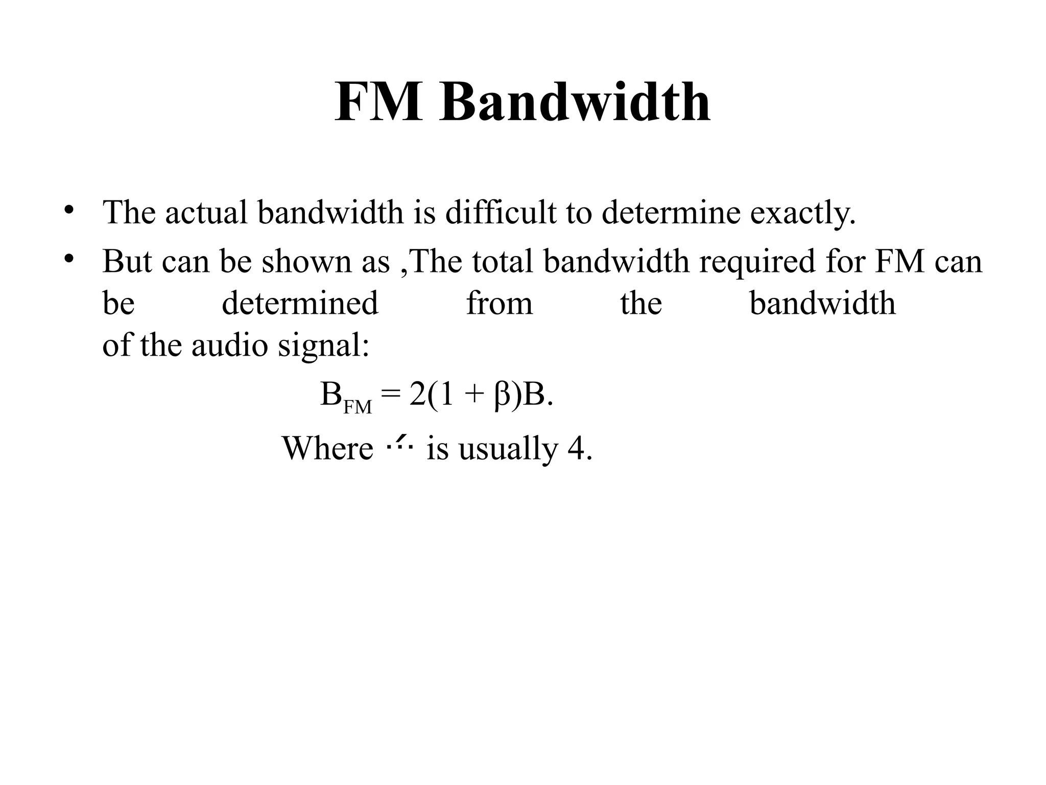
FM Bandwidth
• Theactual bandwidth is difficult to determine exactly.
• But can be shown as ,The total bandwidth required for FM can
be determined from the bandwidth
of the audio signal:
BFM = 2(1 + β)B.
Where is usually 4.
51.
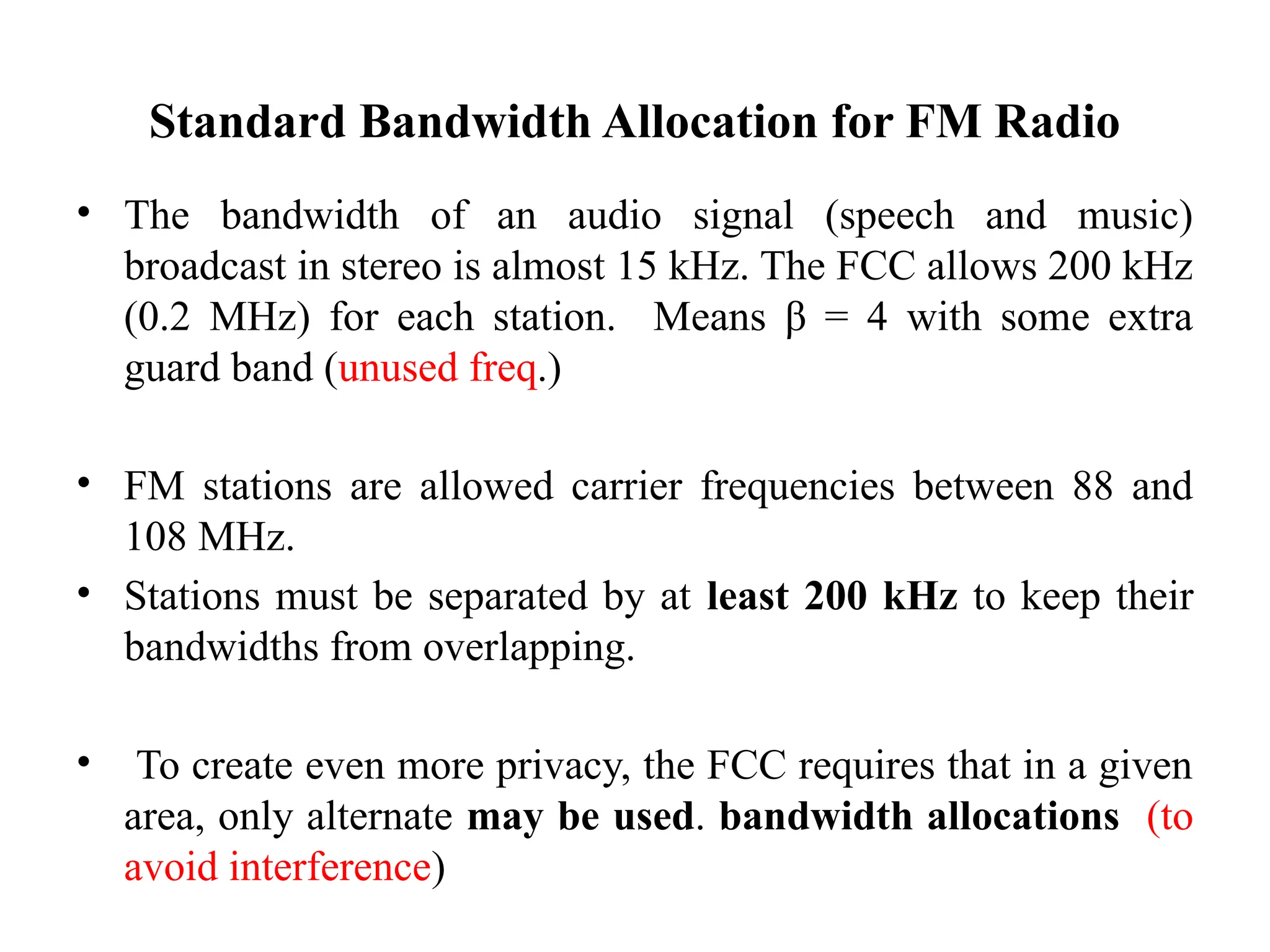
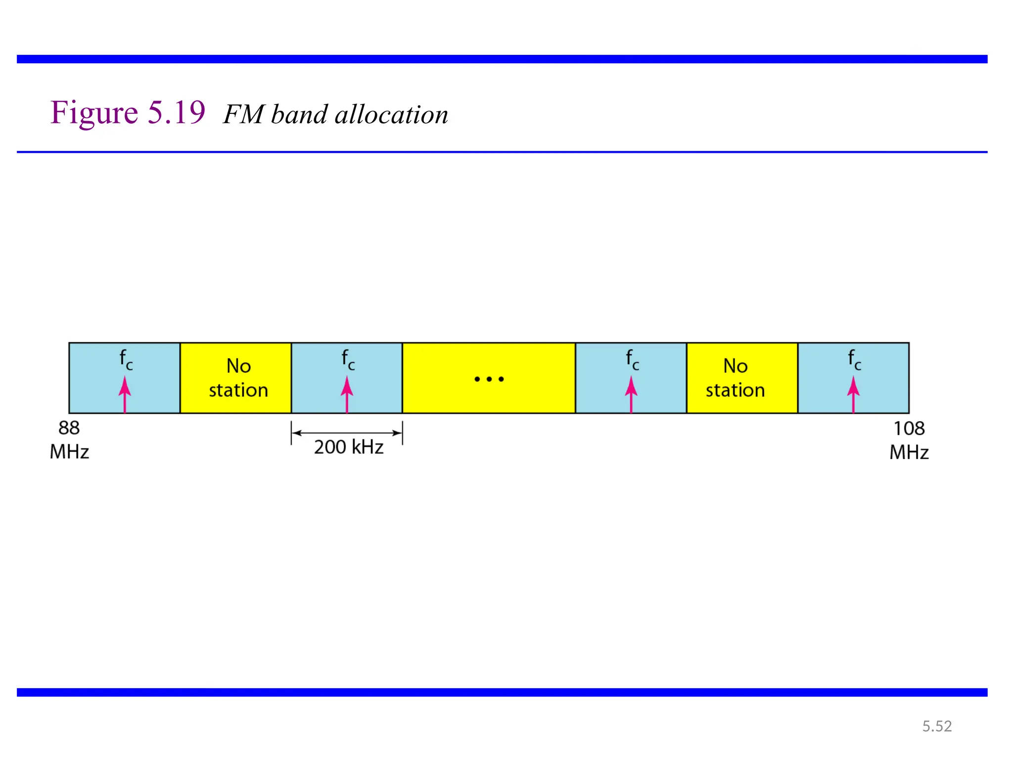
Standard Bandwidth Allocationfor FM Radio
• The bandwidth of an audio signal (speech and music)
broadcast in stereo is almost 15 kHz. The FCC allows 200 kHz
(0.2 MHz) for each station. Means β = 4 with some extra
guard band (unused freq.)
• FM stations are allowed carrier frequencies between 88 and
108 MHz.
• Stations must be separated by at least 200 kHz to keep their
bandwidths from overlapping.
• To create even more privacy, the FCC requires that in a given
area, only alternate may be used. bandwidth allocations (to
avoid interference)
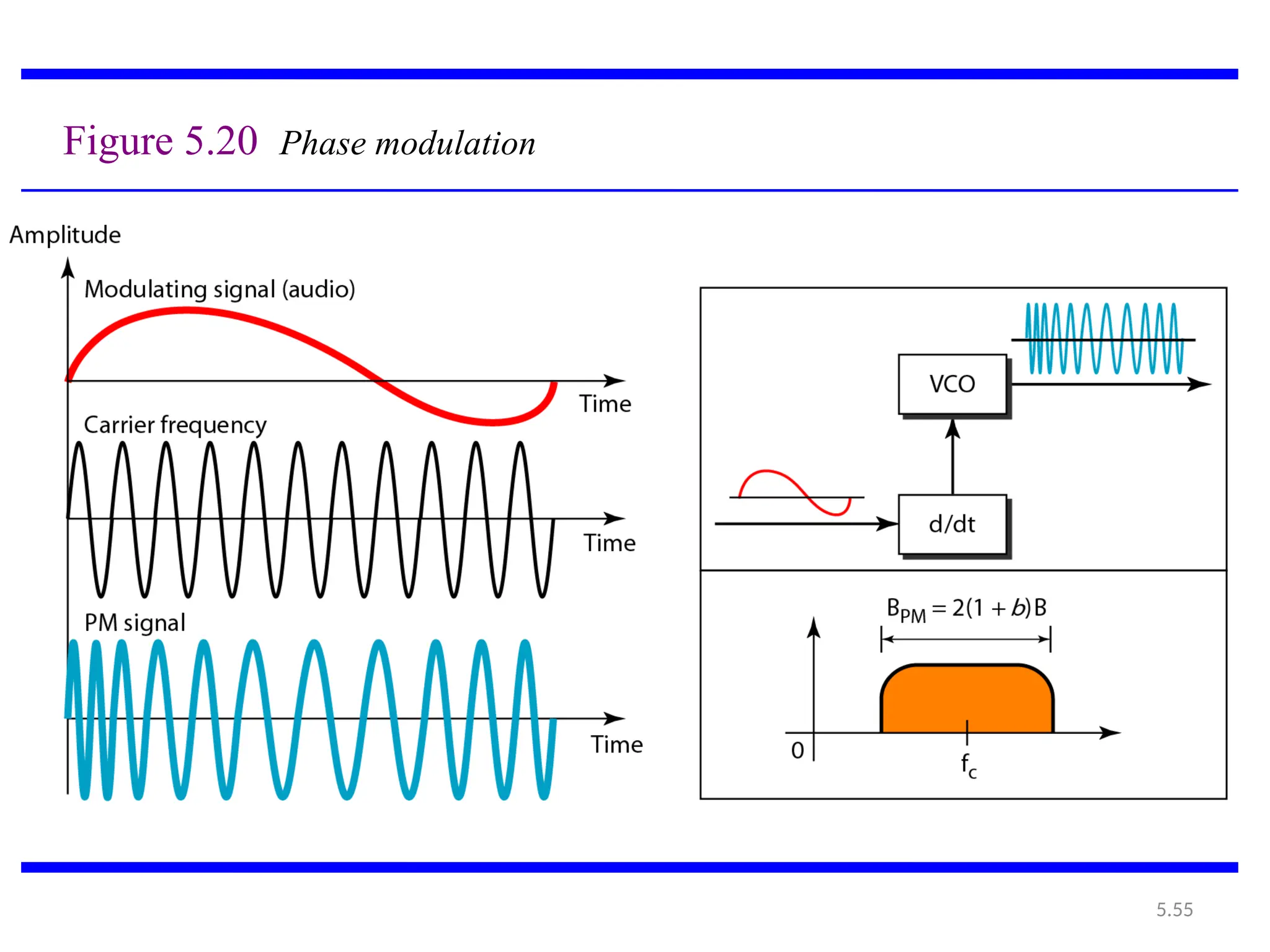
5.2.3 Phase Modulation(PM)
• In PM transmission, the phase of the carrier signal is
modulated to follow the changing voltage level (amplitude)
of the modulating signal.
• The peak amplitude and frequency of the carrier signal
remain constant, but as the amplitude of the information
signal changes, the phase of the carrier changes
correspondingly.
54.
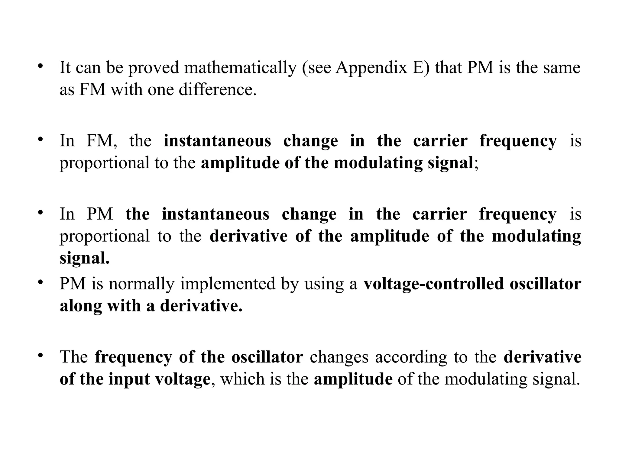
• It canbe proved mathematically (see Appendix E) that PM is the same
as FM with one difference.
• In FM, the instantaneous change in the carrier frequency is
proportional to the amplitude of the modulating signal;
• In PM the instantaneous change in the carrier frequency is
proportional to the derivative of the amplitude of the modulating
signal.
• PM is normally implemented by using a voltage-controlled oscillator
along with a derivative.
• The frequency of the oscillator changes according to the derivative
of the input voltage, which is the amplitude of the modulating signal.
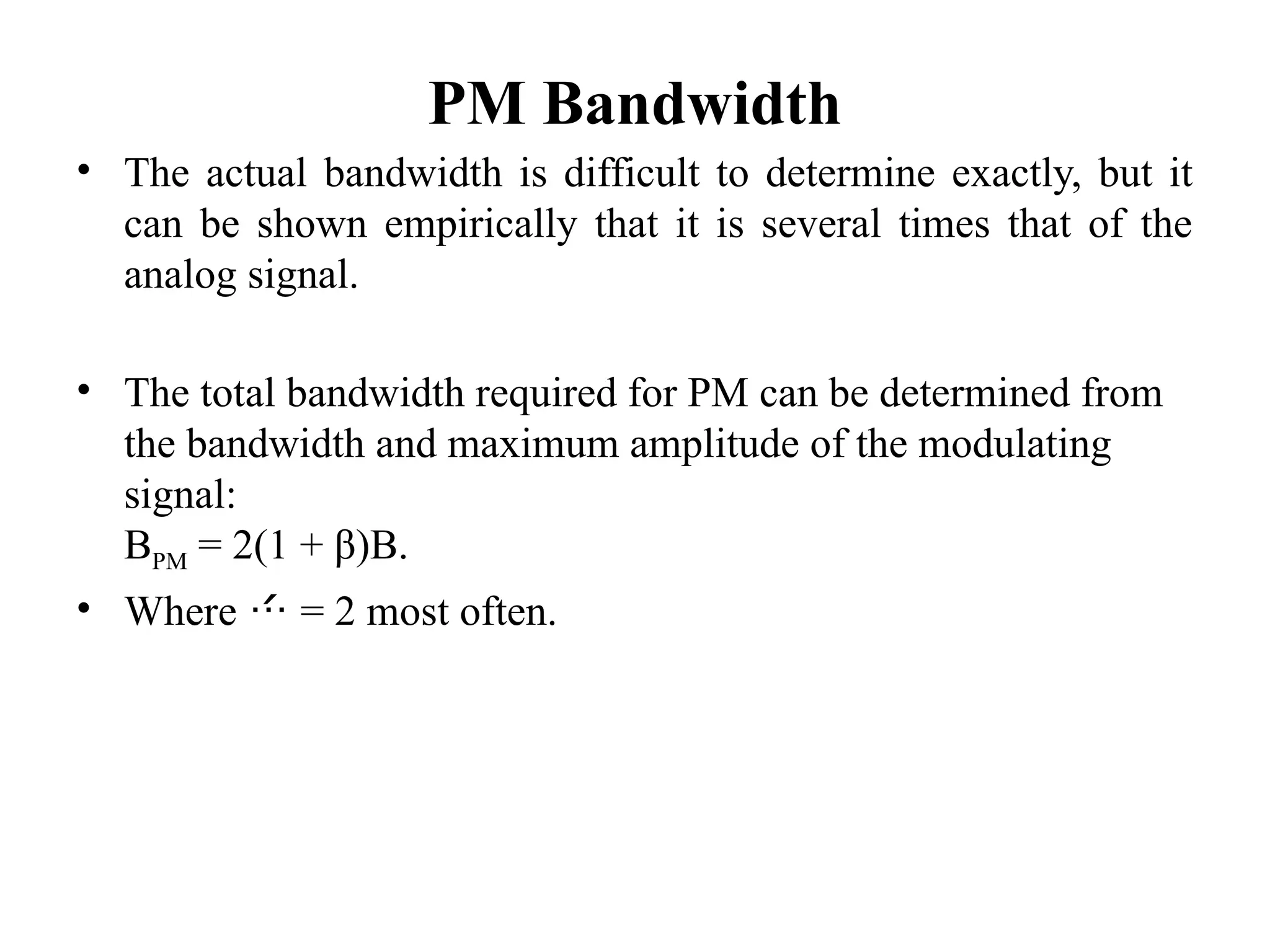
PM Bandwidth
• Theactual bandwidth is difficult to determine exactly, but it
can be shown empirically that it is several times that of the
analog signal.
• The total bandwidth required for PM can be determined from
the bandwidth and maximum amplitude of the modulating
signal:
BPM = 2(1 + β)B.
• Where = 2 most often.


![Chapter 10- Recurrence Relations [Autosaved] by BMN.pptx](https://cdn.slidesharecdn.com/ss_thumbnails/chapter10-recurrencerelationsautosaved-250318181353-89c1945d-thumbnail.jpg?width=640&height=640&fit=bounds)


