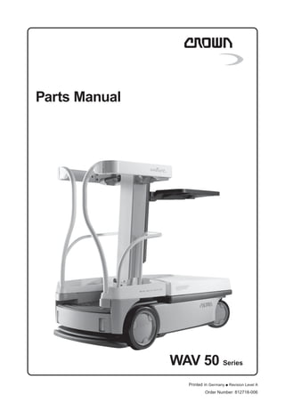
This parts manual provides concise part listings and diagrams for replacing parts on a WAV 50 Series order number 812718-006. It includes 3 sentences or less summaries of each section:
Section 1 covers front chassis parts including the battery, bumpers, and controller mounting plate. Section 2 covers the hydraulic unit. Section 3 covers drive unit parts such as the drive motor and brake assembly. Section 4 covers electrical parts including contactors and switches. Sections 7-10 cover mast, cylinder, platform and miscellaneous parts such as labels and decals.
Komatsu D375A-5E0 Dozer Bulldozer Service Repair Manual S/N 50001 and uphdksemmme
This is the Highly Detailed factory service repair manual for theKOMATSU D375A-5E0 DOZER BULLDOZER, this Service Manual has detailed illustrations as well as step by step instructions,It is 100 percents complete and intact. they are specifically written for the do-it-yourself-er as well as the experienced mechanic.KOMATSU D375A-5E0 DOZER BULLDOZER Service Repair Workshop Manual provides step-by-step instructions based on the complete dis-assembly of the machine. It is this level of detail, along with hundreds of photos and illustrations, that guide the reader through each service and repair procedure. Complete download comes in pdf format which can work under all PC based windows operating system and Mac also, All pages are printable. Using this repair manual is an inexpensive way to keep your vehicle working properly.
Service Repair Manual Covers:
Index and Foreword
Specification
Structure, Function and Maintenance Standard
Standard Value Table
Testing and Adjusting
Troubleshooting
Disassembly and Assembly
Diagrams and Drawings
+++++Field Assembly Instruction
Manual Covers:
Specifications
Precautions for Field Assembly
Disposal of Removed Parts
Assembly Procedure, Necessary Equipment, and Schedule
Layout of Kit
Style for Transportation
Table of Tools for Field Assembly
Tightening Torque
Coating Materials List
File Format: PDF
Compatible: All Versions of Windows & Mac
Language: English
Requirements: Adobe PDF Reader
NO waiting, Buy from responsible seller and get INSTANT DOWNLOAD, Without wasting your hard-owned money on uncertainty or surprise! All pages are is great to haveKOMATSU D375A-5E0 DOZER BULLDOZER Service Repair Workshop Manual.
Looking for some other Service Repair Manual,please check:
https://www.aservicemanualpdf.com/
Thanks for visiting!
8
Ever been troubled by the blinking sign and didn’t know what to do?
Here’s a handy guide to dashboard symbols so that you’ll never be confused again!
Save them for later and save the trouble!
In this presentation, we have discussed a very important feature of BMW X5 cars… the Comfort Access. Things that can significantly limit its functionality. And things that you can try to restore the functionality of such a convenient feature of your vehicle.
Symptoms like intermittent starting and key recognition errors signal potential problems with your Mercedes’ EIS. Use diagnostic steps like error code checks and spare key tests. Professional diagnosis and solutions like EIS replacement ensure safe driving. Consult a qualified technician for accurate diagnosis and repair.
Comprehensive program for Agricultural Finance, the Automotive Sector, and Empowerment . We will define the full scope and provide a detailed two-week plan for identifying strategic partners in each area within Limpopo, including target areas.:
1. Agricultural : Supporting Primary and Secondary Agriculture
• Scope: Provide support solutions to enhance agricultural productivity and sustainability.
• Target Areas: Polokwane, Tzaneen, Thohoyandou, Makhado, and Giyani.
2. Automotive Sector: Partnerships with Mechanics and Panel Beater Shops
• Scope: Develop collaborations with automotive service providers to improve service quality and business operations.
• Target Areas: Polokwane, Lephalale, Mokopane, Phalaborwa, and Bela-Bela.
3. Empowerment : Focusing on Women Empowerment
• Scope: Provide business support support and training to women-owned businesses, promoting economic inclusion.
• Target Areas: Polokwane, Thohoyandou, Musina, Burgersfort, and Louis Trichardt.
We will also prioritize Industrial Economic Zone areas and their priorities.
Sign up on https://profilesmes.online/welcome/
To be eligible:
1. You must have a registered business and operate in Limpopo
2. Generate revenue
3. Sectors : Agriculture ( primary and secondary) and Automative
Women and Youth are encouraged to apply even if you don't fall in those sectors.
Why Is Your BMW X3 Hood Not Responding To Release CommandsDart Auto
Experiencing difficulty opening your BMW X3's hood? This guide explores potential issues like mechanical obstruction, hood release mechanism failure, electrical problems, and emergency release malfunctions. Troubleshooting tips include basic checks, clearing obstructions, applying pressure, and using the emergency release.
Fleet management these days is next to impossible without connected vehicle solutions. Why? Well, fleet trackers and accompanying connected vehicle management solutions tend to offer quite a few hard-to-ignore benefits to fleet managers and businesses alike. Let’s check them out!
5 Warning Signs Your BMW's Intelligent Battery Sensor Needs AttentionBertini's German Motors
IBS monitors and manages your BMW’s battery performance. If it malfunctions, you will have to deal with an array of electrical issues in your vehicle. Recognize warning signs like dimming headlights, frequent battery replacements, and electrical malfunctions to address potential IBS issues promptly.
Core technology of Hyundai Motor Group's EV platform 'E-GMP'Hyundai Motor Group
What’s the force behind Hyundai Motor Group's EV performance and quality?
Maximized driving performance and quick charging time through high-density battery pack and fast charging technology and applicable to various vehicle types!
Discover more about Hyundai Motor Group’s EV platform ‘E-GMP’!
"Trans Failsafe Prog" on your BMW X5 indicates potential transmission issues requiring immediate action. This safety feature activates in response to abnormalities like low fluid levels, leaks, faulty sensors, electrical or mechanical failures, and overheating.
What Does the PARKTRONIC Inoperative, See Owner's Manual Message Mean for You...Autohaus Service and Sales
Learn what "PARKTRONIC Inoperative, See Owner's Manual" means for your Mercedes-Benz. This message indicates a malfunction in the parking assistance system, potentially due to sensor issues or electrical faults. Prompt attention is crucial to ensure safety and functionality. Follow steps outlined for diagnosis and repair in the owner's manual.
Things to remember while upgrading the brakes of your carjennifermiller8137
Upgrading the brakes of your car? Keep these things in mind before doing so. Additionally, start using an OBD 2 GPS tracker so that you never miss a vehicle maintenance appointment. On top of this, a car GPS tracker will also let you master good driving habits that will let you increase the operational life of your car’s brakes.
5. 7
M1.0-0000-0007
7
MP-WAV 50 05/05 • Printed in Germany
INTRODUCTION
MP-WAV 50 05/05 • Printed in Germany M/P-ITD-2350
Important customer information
To ensure the safety of the truck, you, the customer,
must only carry out maintenance and repairs as
stipulated in the operator manual.
Any additional work must be performed by Crown
authorised service technicians. Authorised service
technicians have the required expertise and up-to-date
service information.
If you wish to have your own technicians trained, please
contact Crown for relevant training courses.
Subsequent Attachments and Modifications
made to the Truck
DANGER!
Any proposed modification which would
alter the original condition of the truck
when delivered, must first be assessed and
approved in writing by Crown Gabelstapler
GmbH.
● The net weight and position of
attachments may considerably affect the
capacity and other truck characteristics.
● Changing the electrical system or adding
electrically operated components may
result in operating faults.
Modifications which have not been assessed may
result in fatal accidents!
Ordering Spare Parts
Spare parts can be ordered by quoting:
● The truck specification number
● The truck model number
● The truck serial number
This information can be found on the truck's data plate.
Only if this information is provided can the order be
processed quickly, correctly and reliably.
Please refer to the Technical Specifications Sheet for the
utilisable loads, technical data and dimensions for this
series. Brochures can be obtained from your CROWN
dealer or from the following address:
CROWN Gabelstapler GmbH & CoKG
Moosacher Str. 52
80809 Munich
GERMANY
Tel.: +49 (0)89 / 93 002 -0
Fax: +49 (0)89 / 93 002 -175 oder 133
8. M1.0-0000-00012
M1.0-0000-00012
12
MP-WAV 50 05/05 • Printed in Germany
1
2 3
4
5
16
16
7
8
17
12
12
13
14
15
6
11
18
12
19
20
21
1
1
+
Positive
Terminal
–
Negative
Terminal
B
a
tte
ry
#
1
B
a
tte
ry
#
3
14
FU3
FU
2
B
a
tt
e
ry
C
h
a
rg
e
r
Ma
de
in
U.S
.A.
Inp
ut
Vo
ltag
e:
12
0V
.
AC
Ou
tpu
t
Vo
ltag
e:
24
V.
DC
12
0V
A
C
IN
24
V
D
C
O
U
T
R
E
S
E
T
S
E
A
L
E
D
W
E
T
B
10
B
9
10
6
A
A
C
C
D
D
MP-1.0-2350
MP-2350-001
CHASSIS FRONT
Part 1-3
O
v
e
r
h
e
a
d
V
i
e
w
F
r
o
n
t
R
e
a
r
R
i
g
h
t
L
e
f
t
Cover Screw
Bracket
Panel
9. 13
MP-WAV 50 05/05 • Printed in Germany
INDEX PART NUMBER PART NAME NUMBER REQUIRED
Always Specify Model & Serial Number
To select part number, refer to truck data number.
See Section ITD
MP-1.0-2350
CHASSIS FRONT
1..................... 128748 ..................................... Cover ...................................................................................................... 1
120390 ..................................... Panel ....................................................................................................... 1
130788 ..................................... Front Bracket .......................................................................................... 2
130789 ..................................... Rear Bracket........................................................................................... 2
061094-002 .............................. Screw...................................................................................................... 8
120533 ..................................... Plug ......................................................................................................... 4
2..................... 125323 ..................................... Battery .................................................................................................... 4
060005-008 .............................. Washer ................................................................................................... 8
060030-017 .............................. Washer ................................................................................................... 8
3..................... 125784 ..................................... Bracket ................................................................................................... 2
060024-002 .............................. Nut .......................................................................................................... 2
060030-017 .............................. Washer ................................................................................................... 2
4..................... 120383 ..................................... Rod ......................................................................................................... 2
060000-045 .............................. Roll Pin ................................................................................................... 2
120382 ..................................... Rod Assembly ........................................................................................ 2
5..................... 120241 ..................................... Battery Tray ............................................................................................. 2
6..................... 120251 ..................................... Side Bumper ........................................................................................... 2
060080-007 .............................. Nut .......................................................................................................... 6
060030-098 .............................. Washer ................................................................................................... 6
7..................... 078723-005 .............................. Connector Gray ...................................................................................... 2
078724-005 .............................. Contacts ................................................................................................. 2
060012-078 .............................. Screw...................................................................................................... 2
8..................... 120573 ..................................... Handle .................................................................................................... 1
060012-078 .............................. Screw...................................................................................................... 2
9..................... 060016-096 .............................. Screw...................................................................................................... 2
060030-017 .............................. Washer ................................................................................................... 2
10.................... 120391 ..................................... Front Bumper .......................................................................................... 1
060017-104 .............................. Screw...................................................................................................... 4
11.................... 120357-001 .............................. Side Cover LH ........................................................................................ 1
120357-002 .............................. Side Cover RH........................................................................................ 1
12....................................................................... Service Panel (see Section 4.8).............................................................. 1
120604 ..................................... Spring ..................................................................................................... 1
103418-035 .............................. Spacer .................................................................................................... 2
060030-197 .............................. Washer ................................................................................................... 2
060017-103 .............................. Screw...................................................................................................... 2
13.................... 120202-003 .............................. Battery Charger (220V, 25 A EEC) ......................................................... 1
120202-004 .............................. Battery Charger (240V, 25 A AUS) ......................................................... 1
127039-003 .............................. Circuit Breaker (7 A) ............................................................................... 1
127038-001 .............................. Fuse ........................................................................................................ 1
127037 ..................................... Fuse Holder ............................................................................................ 1
060016-095 .............................. Screw...................................................................................................... 4
795730 ..................................... AC Power Cord (UK) .............................................................................. 1
795731 ..................................... AC Power Cord (EEC) ............................................................................ 1
14....................................................................... Hydraulic Unit (see Section 2.0) ............................................................. 1
120314 ..................................... Vibration Mount ....................................................................................... 3
060080-006 .............................. Nut .......................................................................................................... 3
15....................................................................... Contactor Panel (see Section 4.1) .......................................................... 1
060080-008 .............................. Nut .......................................................................................................... 2
16.................... 133085 ..................................... Controller ................................................................................................ 1
133085-00R-0S ........................ Remanufactured MRC Controller ............................................................ 1
060015-003 .............................. Screw...................................................................................................... 6
060005-007 .............................. Washer ................................................................................................... 6
060021-006 .............................. Nut .......................................................................................................... 6
120433 ..................................... Controller Mounting Plate ........................................................................ 1
060014-080 .............................. Screw...................................................................................................... 6
10. M1.0-0000-00014
M1.0-0000-00014
14
MP-WAV 50 05/05 • Printed in Germany
1
2 3
4
5
16
16
7
8
17
12
12
13
14
15
6
11
18
12
19
20
21
1
1
+
Positive
Terminal
–
Negative
Terminal
B
a
tte
ry
#
1
B
a
tte
ry
#
3
14
FU3
FU
2
B
a
tt
e
ry
C
h
a
rg
e
r
Ma
de
in
U.S
.A.
Inp
ut
Vo
ltag
e:
12
0V
.
AC
Ou
tpu
t
Vo
ltag
e:
24
V.
DC
12
0V
A
C
IN
24
V
D
C
O
U
T
R
E
S
E
T
S
E
A
L
E
D
W
E
T
B
10
B
9
10
6
A
A
C
C
D
D
MP-1.0-2350
MP-2350-001
CHASSIS FRONT
Part 2-3
O
v
e
r
h
e
a
d
V
i
e
w
F
r
o
n
t
R
e
a
r
R
i
g
h
t
L
e
f
t
Cover Screw
Bracket
Panel
11. 15
MP-WAV 50 05/05 • Printed in Germany
INDEX PART NUMBER PART NAME NUMBER REQUIRED
Always Specify Model & Serial Number
To select part number, refer to truck data number.
See Section ITD
MP-1.0-2350
CHASSIS FRONT
17....................................................................... Front Axle (see Section 1.5).................................................................... 1
18.................... 120320-002 .............................. Chassis 2135 mm (84 in.) (see Section 7.2) ........................................... 1
120320-003 .............................. Chassis 2995 mm (118 in.) (see Section 7.2) ......................................... 1
19.................... 125684 ..................................... Cap ......................................................................................................... 2
125685 ..................................... Tube ........................................................................................................ 1
125691 ..................................... Strap Velcro............................................................................................. 2
20.................... 065004-013 .............................. Grommet ................................................................................................. 2
21.................... 065004-014 .............................. Grommet ................................................................................................. 2
12. M1.0-0000-00016
M1.0-0000-00016
16
MP-WAV 50 05/05 • Printed in Germany
6
4
8
5
7
3
11
9
10
9
2
1
TB201
TB202
1
2
3
4
5
6
7
8
9
1
0
1
1
1
3
1
2
1
4
0
61 Nm
(45 ft. lbs.)
MP-1.0-2350
MP-2350-002
CHASSIS REAR
Part 3-3 O
v
e
r
h
e
a
d
V
i
e
w
F
r
o
n
t
R
e
a
r
R
i
g
h
t
L
e
f
t
13. 17
MP-WAV 50 05/05 • Printed in Germany
INDEX PART NUMBER PART NAME NUMBER REQUIRED
Always Specify Model & Serial Number
To select part number, refer to truck data number.
See Section ITD
MP-1.0-2350
CHASSIS REAR
1..................... 065004-013 .............................. Grommet ................................................................................................. 1
2..................... 075256 ..................................... Diode....................................................................................................... 1
060012-079 .............................. Screw...................................................................................................... 2
3..................... 102126-003 .............................. Static Ground Strap ................................................................................ 1
060017-105 .............................. Screw...................................................................................................... 1
4..................... 120394 ..................................... Rear Bumper........................................................................................... 1
060080-007 .............................. Nut .......................................................................................................... 4
5..................... 120310 ..................................... Shim Pad................................................................................................. 2
060015-023 .............................. Screw...................................................................................................... 4
6..................... 120553 ..................................... Drive Motor & Brake Assembly............................................................... 2
060015-064 .............................. Screw...................................................................................................... 8
120581 ..................................... Brush & Cap Kit ...................................................................................... 2
060005-007 .............................. Washer ................................................................................................... 8
120421 ..................................... Drive Unit Assembly (included 5, 6, 7, 9, 10, & 11)................................. 2
126012 ..................................... Brake Assembly ..................................................................................... 2
7..................... 120570 ..................................... Drive Unit ................................................................................................ 2
125764 ..................................... Input Oil Seal .......................................................................................... 1
125765 ..................................... Output Oil Seal ....................................................................................... 1
132246 ..................................... Baffle Vent ............................................................................................... 2
060017-071 .............................. Screw...................................................................................................... 6
060030-197 .............................. Washer ................................................................................................... 6
060021-011 .............................. Nut .......................................................................................................... 6
061004-026 .............................. Adhesive ................................................................................................. AR
8..................... 079564-013 .............................. Terminal Board ........................................................................................ 2
079565-013 .............................. Label ....................................................................................................... 2
060012-077 .............................. Screw...................................................................................................... 4
9..................... 120534 ..................................... Coupler ................................................................................................... 4
125999 ..................................... Drive Motor Coupling Kit (included 9, 10 & 11) ....................................... 2
10.................... 120535 ..................................... Insert Coupler ......................................................................................... 2
11.................... 103418-038 .............................. Spacer .................................................................................................... 2
14. Thank you very much for
your reading. Please Click
Here. Then Get COMPLETE
MANUAL. NO WAITING
NOTE:
If there is no response to
click on the link above,
please download the PDF
document first and then
click on it.
15. M1.0-0000-00018
M1.0-0000-00018
18
MP-WAV 50 05/05 • Printed in Germany
1
2
3
3
3
4
5
3
3
7
10
11
12
6
14
13
6
8
9
15
A
B
C
C
A
B
C
16
17
18
MP-1.5-2350
MP-2350-003
AXLE
Chassis
O
v
e
r
h
e
a
d
V
i
e
w
F
r
o
n
t
R
e
a
r
R
i
g
h
t
L
e
f
t
16. 19
MP-WAV 50 05/05 • Printed in Germany
INDEX PART NUMBER PART NAME NUMBER REQUIRED
Always Specify Model & Serial Number
To select part number, refer to truck data number.
See Section ITD
MP-1.5-2350
AXLE
0..................... 120362 ..................................... Axel (included 2, 3, 5, 6, 7 & 14) ............................................................. 1
1..................... 120580 ..................................... Cap ......................................................................................................... 2
2........................... 060009-086 .............................. Retaining Ring ................................................................................... 2
3........................... 125710 ..................................... Caster Wheel Assembly .................................................................... 2
120578-001 ............................... Caster Wheel ............................................................................... 2
065081-023 ............................... Bearing Ball ................................................................................. 8
4..................... 100779 ..................................... Grease Nipple ......................................................................................... 1
5........................... 120373-002 .............................. Caster Mount RH .............................................................................. 1
6........................... 065117-003 .............................. Bushing ............................................................................................. 2
7........................... 120363 ..................................... Axle ................................................................................................... 1
8..................... 120398 ..................................... Shaft........................................................................................................ 1
9..................... 060017-104 .............................. Screw...................................................................................................... 1
10.................... 064091-009 .............................. Hex Plug ................................................................................................. 2
11.................... 102414 ..................................... Spring ..................................................................................................... 2
12.................... 120370 ..................................... Friction Bar .............................................................................................. 2
13.................... 060009-086 .............................. Retaining Ring ........................................................................................ 2
14.......................... 120373-001 .............................. Caster Mount LH ............................................................................... 1
15.................... 060030-148 .............................. Washer ................................................................................................... AR
16.................... 133849 ..................................... Screw...................................................................................................... 2
17.................... 060080-008 .............................. Nut .......................................................................................................... 2
18.................... 060000-065 .............................. Roll Pin ................................................................................................... 2