Download to read offline
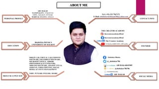
This document provides information about Abubakar Bhutta, including his contact information, skills, education, social media accounts, and personal profile. It lists his phone number, email, languages spoken, software skills, university and degree. He is from Sialkot, Pakistan and his social media accounts are provided.


![COUNTERS [Synchronous and Asynchronous]](https://cdn.slidesharecdn.com/ss_thumbnails/counters-211217083059-thumbnail.jpg?width=640&height=640&fit=bounds)