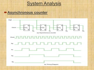
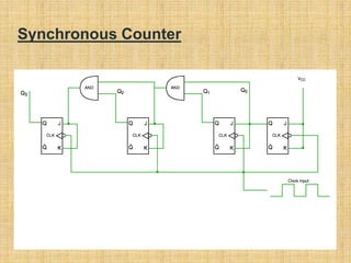
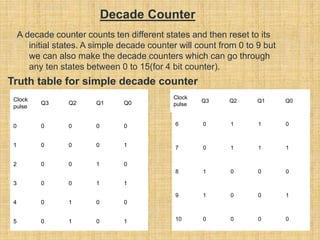
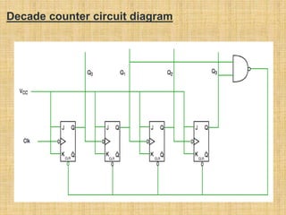
Submitted To:
Miss:
Lecturer
Department of CSE
European University of Bangladesh
Submitted by :
Dipto Ratna -220121050
Taofiqur Rhaman – 220121017
Sheikh Fardin Raj - 2201210
4th Semester
Department of CSE
European University of Bangladesh
Project on Digital Logic Counter
 Introduction
 Counter Classification
 System Analysis
 Design Overview
 Decade Counter
 A Counter is a device which stores (and sometimes displays)
the number of times a particular event or process has
occurred, often in relationship to a clock signal. Counters are
used in digital electronics for counting purpose, they can count
specific event happening in the circuit. For example, in
UP counter a counter increases count for every rising edge of
clock. Not only counting, a counter can follow the certain
sequence based on our design like any random sequence
0,1,3,2… .They can also be designed with the help of flip
flops. They are used as frequency dividers where the
frequency of given pulse waveform is divided. Counters are
sequential circuit that count the number of pulses can be
either in binary code or BCD form. The main properties of a
counter are timing , sequencing , and counting.
Counter works in two modes
 Up counter
 Down counter
Introduction
Counter
Classification
 Counters are broadly divided into two categories
 Asynchronous counter
 Synchronous counter
1. Asynchronous Counter
 In asynchronous counter we don’t use universal clock, only first flip flop is
driven by main clock and the clock input of rest of the following flip flop is
driven by output of previous flip flops. We can understand it by following
diagram- It is evident from timing diagram that Q0 is changing as soon as
the rising edge of clock pulse is encountered, Q1 is changing when rising
edge of Q0 is encountered(because Q0 is like clock pulse for second flip
flop) and so on. In this way ripples are generated through Q0,Q1,Q2,Q3
hence it is also called RIPPLE counter. A ripple counter is a cascaded
arrangement of flip flops where the output of one flip flop drives the clock
input of the following flip flop
( অ্যাসিঙ্ক্রানাি )
( সিঙ্ক্রানাি )
System Analysis
Asynchronous counter
Unlike the asynchronous counter, synchronous
counter has one global clock which drives each flip
flop so output changes in parallel. The one
advantage of synchronous counter over
asynchronous counter is, it can operate on higher
frequency than asynchronous counter as it does
not have cumulative delay because of same clock
is given to each flip flop.
2. Synchronous
Counter
Synchronous Counter
Synchronous counter circuit
 Timing diagram synchronous counter
 From circuit diagram we see that Q0 bit gives response to each falling edge of clock
while Q1 is dependent on Q0, Q2 is dependent on Q1 and Q0 , Q3 is dependent on
Q2,Q1 and Q0.
Decade Counter
A decade counter counts ten different states and then reset to its
initial states. A simple decade counter will count from 0 to 9 but
we can also make the decade counters which can go through
any ten states between 0 to 15(for 4 bit counter).
Clock
pulse
Q3 Q2 Q1 Q0
0 0 0 0 0
1 0 0 0 1
2 0 0 1 0
3 0 0 1 1
4 0 1 0 0
5 0 1 0 1
6 0 1 1 0
7 0 1 1 1
8 1 0 0 0
9 1 0 0 1
10 0 0 0 0
Clock
pulse
Q3 Q2 Q1 Q0
Truth table for simple decade counter
Decade counter circuit diagram
Decade counter
circuit diagram
 We see from circuit diagram that we have used nand gate for Q3 and Q1
and feeding this to clear input line because binary representation of 10
is— 1010
And we see Q3 and Q1 are 1 here, if we give NAND of these two bits to
clear input then counter will be clear at 10 and again start from beginning.
 Important point: Number of flip flops used in counter are always greater
than equal to (log2 n) where n=number of states in counter.
Thank You!

Digital Logic Counter.ppt

  • 1.
    Submitted To: Miss: Lecturer Department ofCSE European University of Bangladesh Submitted by : Dipto Ratna -220121050 Taofiqur Rhaman – 220121017 Sheikh Fardin Raj - 2201210 4th Semester Department of CSE European University of Bangladesh
  • 2.
    Project on DigitalLogic Counter  Introduction  Counter Classification  System Analysis  Design Overview  Decade Counter
  • 3.
     A Counteris a device which stores (and sometimes displays) the number of times a particular event or process has occurred, often in relationship to a clock signal. Counters are used in digital electronics for counting purpose, they can count specific event happening in the circuit. For example, in UP counter a counter increases count for every rising edge of clock. Not only counting, a counter can follow the certain sequence based on our design like any random sequence 0,1,3,2… .They can also be designed with the help of flip flops. They are used as frequency dividers where the frequency of given pulse waveform is divided. Counters are sequential circuit that count the number of pulses can be either in binary code or BCD form. The main properties of a counter are timing , sequencing , and counting. Counter works in two modes  Up counter  Down counter Introduction
  • 4.
    Counter Classification  Counters arebroadly divided into two categories  Asynchronous counter  Synchronous counter 1. Asynchronous Counter  In asynchronous counter we don’t use universal clock, only first flip flop is driven by main clock and the clock input of rest of the following flip flop is driven by output of previous flip flops. We can understand it by following diagram- It is evident from timing diagram that Q0 is changing as soon as the rising edge of clock pulse is encountered, Q1 is changing when rising edge of Q0 is encountered(because Q0 is like clock pulse for second flip flop) and so on. In this way ripples are generated through Q0,Q1,Q2,Q3 hence it is also called RIPPLE counter. A ripple counter is a cascaded arrangement of flip flops where the output of one flip flop drives the clock input of the following flip flop ( অ্যাসিঙ্ক্রানাি ) ( সিঙ্ক্রানাি )
  • 5.
  • 6.
    Unlike the asynchronouscounter, synchronous counter has one global clock which drives each flip flop so output changes in parallel. The one advantage of synchronous counter over asynchronous counter is, it can operate on higher frequency than asynchronous counter as it does not have cumulative delay because of same clock is given to each flip flop. 2. Synchronous Counter
  • 7.
  • 8.
    Synchronous counter circuit Timing diagram synchronous counter  From circuit diagram we see that Q0 bit gives response to each falling edge of clock while Q1 is dependent on Q0, Q2 is dependent on Q1 and Q0 , Q3 is dependent on Q2,Q1 and Q0.
  • 9.
    Decade Counter A decadecounter counts ten different states and then reset to its initial states. A simple decade counter will count from 0 to 9 but we can also make the decade counters which can go through any ten states between 0 to 15(for 4 bit counter). Clock pulse Q3 Q2 Q1 Q0 0 0 0 0 0 1 0 0 0 1 2 0 0 1 0 3 0 0 1 1 4 0 1 0 0 5 0 1 0 1 6 0 1 1 0 7 0 1 1 1 8 1 0 0 0 9 1 0 0 1 10 0 0 0 0 Clock pulse Q3 Q2 Q1 Q0 Truth table for simple decade counter
  • 10.
  • 11.
    Decade counter circuit diagram We see from circuit diagram that we have used nand gate for Q3 and Q1 and feeding this to clear input line because binary representation of 10 is— 1010 And we see Q3 and Q1 are 1 here, if we give NAND of these two bits to clear input then counter will be clear at 10 and again start from beginning.  Important point: Number of flip flops used in counter are always greater than equal to (log2 n) where n=number of states in counter.
  • 12.