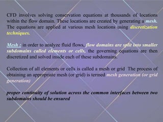
COMPUTATIONAL FLUID
DYNAMICS
Dr. Rajan Swami
MMCP
MM(DU)
INTRODUCTION
⁎Computational fluid dynamics (CFD) is a branch of fluid
mechanics that uses numerical analysis and data structures to analyze
and solve problems that involve fluid flows.
⁎Computers are used to perform the calculations required to simulate
the free-stream flow of the fluid, and the interaction of the fluid
(liquids and gases) with surfaces defined by boundary conditions.
⁎With high-speed supercomputers, better solutions can be achieved,
and are often required to solve the largest and most complex problems.
CFD is applied to a wide range of :
research and engineering problems
In fields of study and industries, including aerodynamics and
aerospace analysis,
weather simulation, natural science and environmental
engineering,
industrial system design and analysis,
biological engineering and fluid flows, and
engine and combustion analysis.
⁂
Computational fluid dynamics
can be a viable tool to analyze
and troubleshoot various
process equipment used in the
pharmaceutical industry.
Because typical unit
operations process large
amounts of fluid, even small
improvements in efficiency
and performance may
increase revenue and decrease
costs.
Overview of CFD methods
CFD methods are based on the first principles of mass, momentum, and
energy conservation, which are described by the following equations:
Mass: Momentum: Energy :
In these equations, ρ is fluid density, t is time, x is coordinate, u is velocity, P
is fluid pressure, H is fluid enthalpy, τ is shear stress, and i, j, k represents the
three coordinate directions. Sm is mass source, Sf represents momentum
source, Sh is energy source
CFD involves solving conservation equations at thousands of locations
within the flow domain. These locations are created by generating a mesh.
The equations are applied at various mesh locations using discretization
techniques.
Mesh : in order to analyze fluid flows, flow domains are split into smaller
subdomains called elements or cells, the governing equations are then
discretized and solved inside each of these subdomains.
Collection of all elements or cells is called a mesh or grid. The process of
obtaining an appropriate mesh (or grid) is termed mesh generation (or grid
generation)
proper continuity of solution across the common interfaces between two
subdomains should be ensured
Discretization techniques : implies replacing the differential
equation governing the Fluid Flow, with a set of algebraic
equations which in turn can be solved with the aid of a digital
computer to get an approximate solution
Discretization methods :
Finite volume method
Finite element method
Finite difference method
The computed solution provides flow variables such as velocity,
pressure, temperature, density, concentration, and so forth at
thousands of locations within the domain.
CFD analysis can be categorized into three main steps:
preprocessing,
solution, and
postprocessing.
PREPROCESSING
Preprocessing involves identifying the flow region of interest,
geometrically representing the region, defining a suitable mesh, and
then applying the principles of flow physics.
Once the region is defined, a computer model of the geometry is
created.
After defining the mesh, the governing equations are solved at
discrete locations in the flow domain. These locations depend on the
resolution of the mesh.
The accuracy of a CFD calculation and the computer time required
for a solution also depend on mesh resolution.
User experience and skill play a crucial role in the choice of a
suitable mesh.
Appropriate boundary conditions are applied to define regions of
inflow, outflow, walls, and other important features.
Physical models within the software are activated to simulate flow
physics pertaining to the application.
Selection of appropriate physical models and their applicability to
the flow physics is critical to the overall accuracy of a CFD solution.
SOLUTION
Once the problem definition is completed, it is submitted to the solver
for the computation of a solution. This is the solution step.
The governing equations are coupled and nonlinear in nature.
Therefore, a guess-and-correct, iterative strategy is adopted to
compute the solution.
Although the solution method is automated, user intervention
frequently is required to obtain a stable converged solution
POSTPROCESSING
CFD results are analyzed in the postprocessing step.
 A CFD solution provides full-field data; flow variables at thousands or
even hundreds of thousands of locations are available.
A representation of the flow field is created by plotting flow variables
in space on a plane, in a line, or in a three-dimensional region of
interest.
However, the real value of CFD simulation often is found in its ability
to provide accurate predictions of integrated quantities such as heat-
transfer rates, mass transfer rates, and forces imposed on the inside of
vessels
ADVANTAGES OF CFD
Gain insight into systems that might be difficult to test through
experimentation.
Foresee performance and optimise the design accordingly. Without
modifying or installing real systems, CFD simulation can forecast which
changes in design are most vital for improving performance.
Predict mass flow rates, pressure drops, heat transfer rates, and fluid
dynamic forces such as lift, drag and pitching moments.
Lower costs by using CFD simulations instead of physical
experimentation to retrieve essential engineering data.
Introduce engineering data early in the design process. Simulations
can be executed in a far shorter period of time when compared to physical
testing
Simulate real conditions. Some flow and heat transfer processes cannot
be physically tested, e.g. hypersonic flow. But CFD provides the ability to
theoretically simulate any physical condition.
Simulate ideal conditions. CFD permits great control over the physical
processes, and offers the ability to isolate specific phenomena for study.
Examine data from a large number of locations. Physical testing limits
the number of locations that can be examined in the system. CFD permits
the examination of a large number of locations in the area of interest, and
yields a comprehensive set of flow parameters for examination.
LIMITATIONS OF CFD
PHYSICAL MODELS
–CFD relies upon physical models of real world processes.
– CFD solutions can only be as accurate as the physical models.
NUMERICAL ERRORS
– Solving equations on a machine also introduces numerical errors, e.g.
Round-off error (due to finite word size available on computer, round-
off errors will always exist).
– Truncation error (due to approximations in the numerical models).
BOUNDARY CONDITIONS
– Similar to physical models.
– The accuracy of the CFD solution is only as good as the initial
boundary conditions provided to the numerical model.
CFD FOR PHARMACEUTICAL
INDUSTRY
CFD FOR MIXING
Mixing processes lie at the heart of the pharmaceutical industry.
A wide variety of mixing equipment such as static mixers, stirred tanks,
homogenizers, and emulsifiers is used.
Mixing processes can involve the blending of two streams of the same
fluid but at different temperatures (thermal mixing), or it can involve
the mixing of two or more different fluids with or without chemical
reactions.
Static mixers for fluid–fluid mixing commonly are used for pastes and
high viscosity fluids.
These mixers operate on the principle of slicing and mixing layers of
fluid.
CFD methods can be applied to examine the performance of static
mixers and to predict the degree of mixing achieved, thus indicating
whether more mixing elements are required.
Figure a shows surface mesh and blade orientation for a Kinecs mixer.
Figure b depicts the mass fraction concentration of the two species being
mixed.
The degree of mixing is shown as the color proceeds from distinct inlet
streams (red and blue) to the fully mixed outlet stream (green). A CFD
solution can be used to derive the pressure drop, hence the power
required.
Stirred tank reactors are the most commonly used equipment in the
pharmaceutical industry. The primary function of these vessels is to
provide adequate stirring and mixing.
CFD methods were used to analyze the flow field and vessel flow
characteristics as well as to describe the influence of impeller location on
the flow field.
The example here in Figure a shows properly placed impellers in the
vessel. The radial flow field generated by the impellers leads to the
formation of four toroidal recirculation regions.
If the impellers are placed closer to each other, a converging flow pattern
is generated (see Figure b). The upper impeller pumps downward, and the
lower impeller pumps upward.
However, if the impellers are placed farther apart, a diverging flow
pattern is generated (see Figure c). In this case, the lower impeller pumps
downward, and the upper impeller continues to pump radially outward.
Changes in impeller position lead to a drastic change in the flow
pattern, which has a strong effect on vessel performance, mixing
characteristics, and hence product quality and efficiency.
Emulsification involves the dispersion of one liquid into another as
small droplets. This process is achieved by the action of high, local shear.
High-speed dispersing units, valve homogenizers, and ultrasonic
emulsifiers commonly are used for such tasks. The power required for
ultrasonic emulsification is less than that used for valve homogenizers. As
a result, ultrasonic homogenizers are preferred over other emulsifiers.
In ultrasonic homogenizers, high-pressure (150 bar) fluid is pumped
through an orifice to produce a high velocity stream over a vibrating
blade. High-frequency vibrations of the blade create cavitation, which
produces high quality emulsions and dispersions.
Parameters such as fluid viscosity, temperature, and the amount of
dissolved gas affect cavitation intensity. Cavitation intensity also is
related to ultrasonic power and ultrasonic frequency.
However, uncontrolled cavitation can be harmful because it can lead to
the pitting and erosion of material.
Manufacturers can improve the performance of ultrasonic emulsifiers by
increasing their understanding of the formation, size, density, speed of
collapse, and intensity of implusion of cavitation bubbles.
Regions of cavitation bubbles can be identified by studying the flow field
around ultrasonic actuators.
CFD methods can be applied to simulate fluid flow and obtain a detailed
understanding of the flow physics.
The influence of actuator frequency and amplitude on cavitation bubble
region formation as well as the transport of cavitation bubble regions
can be studied using CFD techniques.
Figure a shows an ultrasonic emulsifier configuration analyzed using
CFD. Figure b depicts the distribution of volume fraction of liquid
around an ultrasonic oscillating blade (red regions correspond to liquid
regions, and blue regions correspond to vapor regions where cavitation
bubbles reside).
CFD FOR SOLID HANDLING
Nearly 60–80% of pharmaceutical products are in the form of solids. The
handling and transport of solid particles pose several challenges.
At times, particles impact the walls of the transport equipment, thus
increasing the risk of erosion.
CFD techniques can be applied to analyze such flows and minimize or
eliminate the risk of erosion. CFD also can be applied to analyze the
unsteady and chaotic flow behavior in fluidized beds.
Performing calculations can take an extensive amount of time. However,
with the use of fast computers and parallel processing capabilities, one
can simulate the gas–solid flows in complex reactors.
CFD FOR SEPERATION
Crystallization, precipitation, and centrifuge separation are very common
pharmaceutical processes.
Industrial centrifuges typically are used for separating solids from liquids
and in performing liquid–liquid separations
In the following example, design modifications to a centrifuge were
examined using CFD.
The original design (shown in Figure a) resulted in a slugging of material.
As part of the design-change investigations, the concentrate outlet port
(side port) was closed. This caused high-density liquid to exit the low-
density port (an undesirable situation).
Next, the side port opening was reduced. This modification minimized
slugging, which led to a nearsteady flow. Figure b shows the modified
design and fluid-density distribution (red denotes regions of high
density, and blue represents low-density fluid).
CFD FOR DRYERS
Drying equipment usually is large and expensive. As a result, a
dryer’s efficiency influences production and operation cost.
As an example of how CFD can be beneficial in drying applications,
we used CFD to analyze the performance of an industrial spray dryer
before making major structural changes to the dryer.
CFD was applied to examine configuration changes, thus minimizing
risk and avoiding unnecessary downtime during testing.
Figure shows the velocity distribution (skewed flow). This flow is a
result of uneven pressure distribution in the airdispersing head.
CFD models were applied to
determine optimum equipment
configuration and process
settings.
CFD results provided the
necessary confidence that the
proposed modifications would
work so capital equipment
would be ordered and field-
testing could be scheduled.
 CFD FOR PACKAGING
Liquid pharmaceutical products primarily are supplied in bottles, and
decreasing filling time can shorten time-to-market and increase
productivity.
To save time, filling equipment can be adapted to package various
products, but splashing, spillover, and frothing are some of the problems
associated with such filling lines.
CFD can be applied to conduct virtual experiments before changes are
made to the filling lines or to the package geometry. This method allows a
wide range of conditions to be tested and leads to an optimized filling
process.
Figure depicts the filling of a container. The figures shown are typical
of solution results that are used to optimize filling processes to increase
throughput and reduce foaming.
CFD FOR ENERGY GENERATION AND
ENERGY TRANSFER DEVICES
Heat-transfer equipment such as heat exchangers is used throughout a
chemical processing plant. CFD techniques can be applied to analyze
thermal and flow fields within such devices.
Maintaining flame stability and burner efficiency is very critical to the
proper functioning of a process heater, power plant, or furnace.
Flame length, shape, and size can influence the process. If the flame is too
long, then it can impinge on critical regions of the apparatus and cause
thermal damage. If the flame is too short, then it may wear out the burner
tip. Replacing the burner or associated apparatus results in downtime and
loss of product revenue
CONCLUSION
The integration of CFD methods can shorten product-process
development cycles, optimize existing processes, reduce energy
requirements, and lead to the efficient design of new products and
processes.
Unit operations in the pharmaceutical industry handle large amounts of
fluid. As a result, small increments in efficiency, such as those created by
implementing CFD solutions, can lead to significant product cost savings.
The chemical process and the pharmaceutical industries now are
beginning to integrate this technology. The full potential for process
improvements using CFD solutions is yet to be realized.
REFERENCES
Pordal H.S, Matice C.J, and Fry T.J. , Pharmaceutical Technology, The
Role of Computational Fluid Dynamics in the Pharmaceutical Industry,
Page no. 72 to 79
https://redmetal.co.za/engineering-services/computational-fluid-
dynamics-flow-simulation/
https://en.wikipedia.org/wiki/Computational_fluid_dynamics
https://www.cfd-online.com/Wiki/Meshing

coputational fluid dynamics.pptx

  • 1.
  • 2.
    INTRODUCTION ⁎Computational fluid dynamics(CFD) is a branch of fluid mechanics that uses numerical analysis and data structures to analyze and solve problems that involve fluid flows. ⁎Computers are used to perform the calculations required to simulate the free-stream flow of the fluid, and the interaction of the fluid (liquids and gases) with surfaces defined by boundary conditions. ⁎With high-speed supercomputers, better solutions can be achieved, and are often required to solve the largest and most complex problems.
  • 3.
    CFD is appliedto a wide range of : research and engineering problems In fields of study and industries, including aerodynamics and aerospace analysis, weather simulation, natural science and environmental engineering, industrial system design and analysis, biological engineering and fluid flows, and engine and combustion analysis.
  • 4.
    ⁂ Computational fluid dynamics canbe a viable tool to analyze and troubleshoot various process equipment used in the pharmaceutical industry. Because typical unit operations process large amounts of fluid, even small improvements in efficiency and performance may increase revenue and decrease costs.
  • 6.
    Overview of CFDmethods CFD methods are based on the first principles of mass, momentum, and energy conservation, which are described by the following equations: Mass: Momentum: Energy : In these equations, ρ is fluid density, t is time, x is coordinate, u is velocity, P is fluid pressure, H is fluid enthalpy, τ is shear stress, and i, j, k represents the three coordinate directions. Sm is mass source, Sf represents momentum source, Sh is energy source
  • 7.
    CFD involves solvingconservation equations at thousands of locations within the flow domain. These locations are created by generating a mesh. The equations are applied at various mesh locations using discretization techniques. Mesh : in order to analyze fluid flows, flow domains are split into smaller subdomains called elements or cells, the governing equations are then discretized and solved inside each of these subdomains. Collection of all elements or cells is called a mesh or grid. The process of obtaining an appropriate mesh (or grid) is termed mesh generation (or grid generation) proper continuity of solution across the common interfaces between two subdomains should be ensured
  • 8.
    Discretization techniques :implies replacing the differential equation governing the Fluid Flow, with a set of algebraic equations which in turn can be solved with the aid of a digital computer to get an approximate solution Discretization methods : Finite volume method Finite element method Finite difference method The computed solution provides flow variables such as velocity, pressure, temperature, density, concentration, and so forth at thousands of locations within the domain.
  • 9.
    CFD analysis canbe categorized into three main steps: preprocessing, solution, and postprocessing.
  • 10.
    PREPROCESSING Preprocessing involves identifyingthe flow region of interest, geometrically representing the region, defining a suitable mesh, and then applying the principles of flow physics. Once the region is defined, a computer model of the geometry is created. After defining the mesh, the governing equations are solved at discrete locations in the flow domain. These locations depend on the resolution of the mesh.
  • 11.
    The accuracy ofa CFD calculation and the computer time required for a solution also depend on mesh resolution. User experience and skill play a crucial role in the choice of a suitable mesh. Appropriate boundary conditions are applied to define regions of inflow, outflow, walls, and other important features. Physical models within the software are activated to simulate flow physics pertaining to the application. Selection of appropriate physical models and their applicability to the flow physics is critical to the overall accuracy of a CFD solution.
  • 12.
    SOLUTION Once the problemdefinition is completed, it is submitted to the solver for the computation of a solution. This is the solution step. The governing equations are coupled and nonlinear in nature. Therefore, a guess-and-correct, iterative strategy is adopted to compute the solution. Although the solution method is automated, user intervention frequently is required to obtain a stable converged solution
  • 13.
    POSTPROCESSING CFD results areanalyzed in the postprocessing step.  A CFD solution provides full-field data; flow variables at thousands or even hundreds of thousands of locations are available. A representation of the flow field is created by plotting flow variables in space on a plane, in a line, or in a three-dimensional region of interest. However, the real value of CFD simulation often is found in its ability to provide accurate predictions of integrated quantities such as heat- transfer rates, mass transfer rates, and forces imposed on the inside of vessels
  • 14.
    ADVANTAGES OF CFD Gaininsight into systems that might be difficult to test through experimentation. Foresee performance and optimise the design accordingly. Without modifying or installing real systems, CFD simulation can forecast which changes in design are most vital for improving performance. Predict mass flow rates, pressure drops, heat transfer rates, and fluid dynamic forces such as lift, drag and pitching moments. Lower costs by using CFD simulations instead of physical experimentation to retrieve essential engineering data.
  • 15.
    Introduce engineering dataearly in the design process. Simulations can be executed in a far shorter period of time when compared to physical testing Simulate real conditions. Some flow and heat transfer processes cannot be physically tested, e.g. hypersonic flow. But CFD provides the ability to theoretically simulate any physical condition. Simulate ideal conditions. CFD permits great control over the physical processes, and offers the ability to isolate specific phenomena for study. Examine data from a large number of locations. Physical testing limits the number of locations that can be examined in the system. CFD permits the examination of a large number of locations in the area of interest, and yields a comprehensive set of flow parameters for examination.
  • 16.
    LIMITATIONS OF CFD PHYSICALMODELS –CFD relies upon physical models of real world processes. – CFD solutions can only be as accurate as the physical models. NUMERICAL ERRORS – Solving equations on a machine also introduces numerical errors, e.g. Round-off error (due to finite word size available on computer, round- off errors will always exist). – Truncation error (due to approximations in the numerical models). BOUNDARY CONDITIONS – Similar to physical models. – The accuracy of the CFD solution is only as good as the initial boundary conditions provided to the numerical model.
  • 17.
    CFD FOR PHARMACEUTICAL INDUSTRY CFDFOR MIXING Mixing processes lie at the heart of the pharmaceutical industry. A wide variety of mixing equipment such as static mixers, stirred tanks, homogenizers, and emulsifiers is used. Mixing processes can involve the blending of two streams of the same fluid but at different temperatures (thermal mixing), or it can involve the mixing of two or more different fluids with or without chemical reactions.
  • 18.
    Static mixers forfluid–fluid mixing commonly are used for pastes and high viscosity fluids. These mixers operate on the principle of slicing and mixing layers of fluid. CFD methods can be applied to examine the performance of static mixers and to predict the degree of mixing achieved, thus indicating whether more mixing elements are required. Figure a shows surface mesh and blade orientation for a Kinecs mixer. Figure b depicts the mass fraction concentration of the two species being mixed.
  • 19.
    The degree ofmixing is shown as the color proceeds from distinct inlet streams (red and blue) to the fully mixed outlet stream (green). A CFD solution can be used to derive the pressure drop, hence the power required.
  • 20.
    Stirred tank reactorsare the most commonly used equipment in the pharmaceutical industry. The primary function of these vessels is to provide adequate stirring and mixing. CFD methods were used to analyze the flow field and vessel flow characteristics as well as to describe the influence of impeller location on the flow field. The example here in Figure a shows properly placed impellers in the vessel. The radial flow field generated by the impellers leads to the formation of four toroidal recirculation regions. If the impellers are placed closer to each other, a converging flow pattern is generated (see Figure b). The upper impeller pumps downward, and the lower impeller pumps upward.
  • 21.
    However, if theimpellers are placed farther apart, a diverging flow pattern is generated (see Figure c). In this case, the lower impeller pumps downward, and the upper impeller continues to pump radially outward. Changes in impeller position lead to a drastic change in the flow pattern, which has a strong effect on vessel performance, mixing characteristics, and hence product quality and efficiency.
  • 22.
    Emulsification involves thedispersion of one liquid into another as small droplets. This process is achieved by the action of high, local shear. High-speed dispersing units, valve homogenizers, and ultrasonic emulsifiers commonly are used for such tasks. The power required for ultrasonic emulsification is less than that used for valve homogenizers. As a result, ultrasonic homogenizers are preferred over other emulsifiers. In ultrasonic homogenizers, high-pressure (150 bar) fluid is pumped through an orifice to produce a high velocity stream over a vibrating blade. High-frequency vibrations of the blade create cavitation, which produces high quality emulsions and dispersions. Parameters such as fluid viscosity, temperature, and the amount of dissolved gas affect cavitation intensity. Cavitation intensity also is related to ultrasonic power and ultrasonic frequency.
  • 23.
    However, uncontrolled cavitationcan be harmful because it can lead to the pitting and erosion of material. Manufacturers can improve the performance of ultrasonic emulsifiers by increasing their understanding of the formation, size, density, speed of collapse, and intensity of implusion of cavitation bubbles. Regions of cavitation bubbles can be identified by studying the flow field around ultrasonic actuators. CFD methods can be applied to simulate fluid flow and obtain a detailed understanding of the flow physics. The influence of actuator frequency and amplitude on cavitation bubble region formation as well as the transport of cavitation bubble regions can be studied using CFD techniques.
  • 24.
    Figure a showsan ultrasonic emulsifier configuration analyzed using CFD. Figure b depicts the distribution of volume fraction of liquid around an ultrasonic oscillating blade (red regions correspond to liquid regions, and blue regions correspond to vapor regions where cavitation bubbles reside).
  • 25.
    CFD FOR SOLIDHANDLING Nearly 60–80% of pharmaceutical products are in the form of solids. The handling and transport of solid particles pose several challenges. At times, particles impact the walls of the transport equipment, thus increasing the risk of erosion. CFD techniques can be applied to analyze such flows and minimize or eliminate the risk of erosion. CFD also can be applied to analyze the unsteady and chaotic flow behavior in fluidized beds. Performing calculations can take an extensive amount of time. However, with the use of fast computers and parallel processing capabilities, one can simulate the gas–solid flows in complex reactors.
  • 26.
    CFD FOR SEPERATION Crystallization,precipitation, and centrifuge separation are very common pharmaceutical processes. Industrial centrifuges typically are used for separating solids from liquids and in performing liquid–liquid separations In the following example, design modifications to a centrifuge were examined using CFD. The original design (shown in Figure a) resulted in a slugging of material. As part of the design-change investigations, the concentrate outlet port (side port) was closed. This caused high-density liquid to exit the low- density port (an undesirable situation).
  • 27.
    Next, the sideport opening was reduced. This modification minimized slugging, which led to a nearsteady flow. Figure b shows the modified design and fluid-density distribution (red denotes regions of high density, and blue represents low-density fluid).
  • 28.
    CFD FOR DRYERS Dryingequipment usually is large and expensive. As a result, a dryer’s efficiency influences production and operation cost. As an example of how CFD can be beneficial in drying applications, we used CFD to analyze the performance of an industrial spray dryer before making major structural changes to the dryer. CFD was applied to examine configuration changes, thus minimizing risk and avoiding unnecessary downtime during testing. Figure shows the velocity distribution (skewed flow). This flow is a result of uneven pressure distribution in the airdispersing head.
  • 29.
    CFD models wereapplied to determine optimum equipment configuration and process settings. CFD results provided the necessary confidence that the proposed modifications would work so capital equipment would be ordered and field- testing could be scheduled.
  • 30.
     CFD FORPACKAGING Liquid pharmaceutical products primarily are supplied in bottles, and decreasing filling time can shorten time-to-market and increase productivity. To save time, filling equipment can be adapted to package various products, but splashing, spillover, and frothing are some of the problems associated with such filling lines. CFD can be applied to conduct virtual experiments before changes are made to the filling lines or to the package geometry. This method allows a wide range of conditions to be tested and leads to an optimized filling process.
  • 31.
    Figure depicts thefilling of a container. The figures shown are typical of solution results that are used to optimize filling processes to increase throughput and reduce foaming.
  • 32.
    CFD FOR ENERGYGENERATION AND ENERGY TRANSFER DEVICES Heat-transfer equipment such as heat exchangers is used throughout a chemical processing plant. CFD techniques can be applied to analyze thermal and flow fields within such devices. Maintaining flame stability and burner efficiency is very critical to the proper functioning of a process heater, power plant, or furnace. Flame length, shape, and size can influence the process. If the flame is too long, then it can impinge on critical regions of the apparatus and cause thermal damage. If the flame is too short, then it may wear out the burner tip. Replacing the burner or associated apparatus results in downtime and loss of product revenue
  • 33.
    CONCLUSION The integration ofCFD methods can shorten product-process development cycles, optimize existing processes, reduce energy requirements, and lead to the efficient design of new products and processes. Unit operations in the pharmaceutical industry handle large amounts of fluid. As a result, small increments in efficiency, such as those created by implementing CFD solutions, can lead to significant product cost savings. The chemical process and the pharmaceutical industries now are beginning to integrate this technology. The full potential for process improvements using CFD solutions is yet to be realized.
  • 34.
    REFERENCES Pordal H.S, MaticeC.J, and Fry T.J. , Pharmaceutical Technology, The Role of Computational Fluid Dynamics in the Pharmaceutical Industry, Page no. 72 to 79 https://redmetal.co.za/engineering-services/computational-fluid- dynamics-flow-simulation/ https://en.wikipedia.org/wiki/Computational_fluid_dynamics https://www.cfd-online.com/Wiki/Meshing