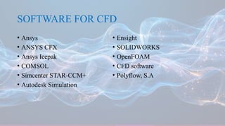
COMPUTATIONAL FLUID
DYNAMICS
BY
DHARANI M
M.PHARM 2ND
SEM
DEPARTMENT OF PHARMACEUTICS
CONTENT
• Introduction
• CFD
• Advantage & Disadvantage
• Role of CFD
• Steps in CFD
• Application of CFD
• Previous work on CFD
• Reference
INTRODUCTION
• Fluid mechanics studies fluid performance at rest and in motion.
• It can be divided into:
fluid statics - the study of fluids at rest
fluid kinematics -the study of fluid in motions
fluid dynamics - effects of forces on fluid motion.
• With the evolution in computer technology, a branch of fluid dynamics called
computational fluid dynamics (CFD) has become a powerful and cost- effective tool for
simulating real fluid flow.
CFD
• CFD is an area of fluid dynamics that deals with finding numerical solutions to equations
describing the fluid flow to obtain a numerical description of the entire flow field.
• CFD offers significant time and cost savings, as well as comprehensive information about fluid
flow in the investigated system, whereas experimental methods are limited to measurements at
certain locations in the system.
• Moreover, numerical simulations allow testing of the system under conditions in which it is not
possible or is difficult to perform experimental tests.
• CFD software packages are based on highly complex nonlinear mathematical expressions derived
from fundamental equations of fluid flow, heat, and mass transfer, and can be solved by complex
algorithms built into the program.
• Fluid flow in a given system can be simulated for defined inlet and outlet conditions (also called
boundary conditions).Modeling outputs are usually presented numerically or graphically.
• The kind of equations describing fluid flow are differential equations, which represent the
relationship between flow variables and their evolution in time and space.
• Basic equations of fluid flow include
Euler’s equations - inviscid flow
Navier–Stokes equations - laminar flow of viscous fluid and turbulent flow
Path- lines of fl uid fl ow tracked with time for 5 seconds from an initial plane 0.5 mm above the
base of the USP paddle dissolution vessel at 25, 50, 100, and 150 rpm (reprinted from McCarthy
et al., 2004; with permission from Springer)
ADVANTAGES OF CFD
• A great time reduction and cost reduction in new designs.
• There is a possibility to analyze different problem whose experiments are very difficult and
dangerous.
• The CFD techniques offer the capacity of studying system under conditions over its limits.
• The level of detail is practically unlimited.
• The product gets added value.
• The possibility to generate different graph permits to understand the features of the result. This
encourages buying a new product.
• Hi-Tech CFD is a computer aided engineering company which provides total solutions to
engineering problems in the field of Computational Fluid Dynamics (CFD), Computational
Electromagnetic, Computational Structural Mechanics, Dynamics and Controls.
DISADVANTAGES OF CFD
• Accuracy in the result is doubted i.e. in certain situations we will not obtain successful result.
• It is necessary to simplify mathematically the phenomenon to facilitate calculus. If the
simplification has been good the result will be more accurate.
• There are several incomplete models to describe the turbulence, multiphase phenomenon, and
other difficult problems.
• Untrained user of CFD has the tendency to believe that the output of the pc is always true
ROLES OF CFD
STEPS IN PERFORMING CFD ANALYSIS
APPLICATION OF CFD IN
PHARMACEUTICS
The application of CFD to a few key unit operations and processes in the pharmaceutical
industry was described as follows:
• CFD for mixing
• CFD for solids handling
• CFD for separation
• CFD for dryers
• CFD for packaging
CFD FOR MIXING:
• CFD methods can be applied to examine the performance of static mixers and to predict the degree
of mixing achieved, thus indicating whether more mixing elements are required shows surface
mesh and blade orientation for a Kinecs mixer depicts the mass fraction concentration of the two
species being mixed.
• The degree of mixing is shown as the color proceeds from distinct inlet streams (red and blue) to
the fully mixed outlet stream (green).
• A CFD solution can be used to derive the pressure drop, hence the power required.
(a) Kinecs mixer, blade orientation (b) mass fraction
contours
CFD FOR SEPARATION:
• CFD techniques are used for analyzing separation devices such as cyclones and scrubbers.
• The following example incorporates CFD methods to optimize and predict performance of
an existing cyclone design.
• CFD solutions depict particle paths for various particle sizes.
• In this example, CFD techniques were used to perform what-if analysis for optimization of
the design.
• The performance computed with CFD closely matched that observed in physical testing
wherein 90% of 10-m particles were removed, but only 10% of 1-m particles were separated
from the air stream
(a) cyclone, pathline of 1-m particle (b) cyclone, pathline
of 10m particle.
CFD FOR DRYERS:
• We used CFD to analyze the performance of an industrial spray dryer before making major
structural changes to the dryer.
• This strategy minimizes the risk of lost profit during changeover, especially if the improvement
does not materialize.
• CFD was applied to examine configuration changes, thus minimizing risk and avoiding
unnecessary downtime during testing shows the velocity distribution (skewed flow).
• This flow is a result of uneven pressure distribution in the air dispersing head.
• CFD models were applied to determine optimum equipment configuration and process settings.
• CFD results provided the necessary confidence that the proposed modifications would work so
capital equipment would be ordered and field- testing could be scheduled
CFD FOR SPRAY DRYING
CFD FOR PACKAGING:
• CFD can be applied to conduct virtual experiments before changes are made to the filling lines or
to the package geometry.
• This method allows a wide range of conditions to be tested and leads to an optimized filling
process, depicts the filling of a container.
• The figures shown are typical of solution results that are used to optimize filling processes to
increase throughput and reduce foaming
a) filling process, liquid surface location, strong splash (b) filling process, liquid surface location, no splash.
CURRENT CHALLENGES/FUTURE
ASPECT
• The integration of CFD methods can shorten product-process development cycles, optimize
existing processes, reduce energy requirements, and lead to the efficient design of new products
and processes.
• Unit operations in the pharmaceutical industry handle large amounts of fluid. As a result, small
increments in efficiency, such as those created by implementing CFD solutions, can lead to
significant product cost savings.
• Key processes in the pharmaceutical industry can be improved with CFD techniques.
• The aerospace and automobile industries already have integrated CFD methods into their design
process.
• The chemical process and the pharmaceutical industries now are beginning to integrate this
technology.
• The full potential for process improvements using CFD solutions is yet to be realized.
PREVIOUS WORK ON CFD
1) Coates et al. have extensively investigated the influence of various design features on DPI
performance by using CFD (Coates et al., 2004, 2005, 2006, 2007).
• An interesting study conducted by this research group is related to the influence of grid structure
and mouthpiece length on device performance (Coates et al., 2004). A flow rate of 60 L/min,
which is the flow rate that can be easily achieved by the patient, was applied in this study, and
laser Doppler velocimetry techniques were used for validation of computational results.
• Changes were made in the structure of the complete grid, and two additional modified grids were
obtained. It was shown that grid structure significantly influenced the flow field in the mouthpiece.
• With the increase of grid voidage, the straightening effect of the grid on airflow decreased, leading
to an increased amount of powder retained within the device.
• The mouthpiece length was found to have less significant influence on inhaler performance, with
slightly reduced device retention in a shorter mouthpiece.
(a) full grid case (b) grid case 1 (c) grid case 2
CFD simulated particle tracks of dispersed powder:
(a) full grid case (b) grid case 1 (c) grid case
2
2) Extensive work has been carried out by a research group at the School of Pharmacy, Trinity
College, Dublin, to elucidate hydrodynamics in paddle dissolution apparatus by using CFD
simulations (McCarthy et al., 2003, 2004; D’Arcy et al., 2005). McCarthy et al. (2003) revealed the
presence of a low- velocity domain directly below the center of the rotating paddle.
3) Chua et al. (2011) used theoretical analysis coupled with CFD simulations to predict
granule–granule and droplet–granule collision rates of fluidized bed melt granulation in a top-
spray granulator.
• CFD simulations provided interesting information about hydrodynamics in the region
around the spray nozzle. Higher granular temperature was observed around the spray
nozzle, indicating higher collision rates in this region .
• Due to the atomizing air flow effects, granules within the spray zone are rapidly pushed
towards the bottom, resulting in solids concentrated at the walls.
• The range of granule–granule and droplet–granule collision rates was determined, and
droplet–granule collision was found to be much faster, but slowed exponentially when
moving away from the spray nozzle.
(a) granular temperature (b) solid velocity magnitude (c) solid
concentration
SOFTWARE FOR CFD
• Ansys
• ANSYS CFX
• Ansys Icepak
• COMSOL
• Simcenter STAR-CCM+
• Autodesk Simulation
• Ensight
• SOLIDWORKS
• OpenFOAM
• CFD software
• Polyflow, S.A
REFERENCE
• Blazek , J. ( 2005 ) Computational Fluid Mechanics: Principles and Application .Oxford, UK :
Elsevier .
• Fay , J.A. ( 1994 ) Introduction to Fluid Mechanics . Cambridge, MA : MIT Press .
• Fries , L. , Antonyuk , S. , Heinrich , S. , and Palzer , S. ( 2011 ) ‘ DEM–CFD modeling of a fl
uidized bed spray granulator ’, Chem. Eng. Sci. , 66 : 2340 – 55 .
• Lohner , R. , Cebral , J. , Soto , O. , Yim , P. , and Burgess , J.E. ( 2003 ) ‘ Applications of patient-
specifi c CFD in medicine and life sciences ’, Int. J. Numer. Meth. Fluids , 43 : 637 – 50 .

COMPUTATIONAL FLUID DYNAMICS [Autosaved] (1).pptx

  • 1.
    COMPUTATIONAL FLUID DYNAMICS BY DHARANI M M.PHARM2ND SEM DEPARTMENT OF PHARMACEUTICS
  • 2.
    CONTENT • Introduction • CFD •Advantage & Disadvantage • Role of CFD • Steps in CFD • Application of CFD • Previous work on CFD • Reference
  • 3.
    INTRODUCTION • Fluid mechanicsstudies fluid performance at rest and in motion. • It can be divided into: fluid statics - the study of fluids at rest fluid kinematics -the study of fluid in motions fluid dynamics - effects of forces on fluid motion. • With the evolution in computer technology, a branch of fluid dynamics called computational fluid dynamics (CFD) has become a powerful and cost- effective tool for simulating real fluid flow.
  • 4.
    CFD • CFD isan area of fluid dynamics that deals with finding numerical solutions to equations describing the fluid flow to obtain a numerical description of the entire flow field. • CFD offers significant time and cost savings, as well as comprehensive information about fluid flow in the investigated system, whereas experimental methods are limited to measurements at certain locations in the system. • Moreover, numerical simulations allow testing of the system under conditions in which it is not possible or is difficult to perform experimental tests. • CFD software packages are based on highly complex nonlinear mathematical expressions derived from fundamental equations of fluid flow, heat, and mass transfer, and can be solved by complex algorithms built into the program. • Fluid flow in a given system can be simulated for defined inlet and outlet conditions (also called boundary conditions).Modeling outputs are usually presented numerically or graphically.
  • 5.
    • The kindof equations describing fluid flow are differential equations, which represent the relationship between flow variables and their evolution in time and space. • Basic equations of fluid flow include Euler’s equations - inviscid flow Navier–Stokes equations - laminar flow of viscous fluid and turbulent flow Path- lines of fl uid fl ow tracked with time for 5 seconds from an initial plane 0.5 mm above the base of the USP paddle dissolution vessel at 25, 50, 100, and 150 rpm (reprinted from McCarthy et al., 2004; with permission from Springer)
  • 6.
    ADVANTAGES OF CFD •A great time reduction and cost reduction in new designs. • There is a possibility to analyze different problem whose experiments are very difficult and dangerous. • The CFD techniques offer the capacity of studying system under conditions over its limits. • The level of detail is practically unlimited. • The product gets added value. • The possibility to generate different graph permits to understand the features of the result. This encourages buying a new product. • Hi-Tech CFD is a computer aided engineering company which provides total solutions to engineering problems in the field of Computational Fluid Dynamics (CFD), Computational Electromagnetic, Computational Structural Mechanics, Dynamics and Controls.
  • 7.
    DISADVANTAGES OF CFD •Accuracy in the result is doubted i.e. in certain situations we will not obtain successful result. • It is necessary to simplify mathematically the phenomenon to facilitate calculus. If the simplification has been good the result will be more accurate. • There are several incomplete models to describe the turbulence, multiphase phenomenon, and other difficult problems. • Untrained user of CFD has the tendency to believe that the output of the pc is always true
  • 8.
  • 9.
    STEPS IN PERFORMINGCFD ANALYSIS
  • 10.
    APPLICATION OF CFDIN PHARMACEUTICS The application of CFD to a few key unit operations and processes in the pharmaceutical industry was described as follows: • CFD for mixing • CFD for solids handling • CFD for separation • CFD for dryers • CFD for packaging
  • 11.
    CFD FOR MIXING: •CFD methods can be applied to examine the performance of static mixers and to predict the degree of mixing achieved, thus indicating whether more mixing elements are required shows surface mesh and blade orientation for a Kinecs mixer depicts the mass fraction concentration of the two species being mixed. • The degree of mixing is shown as the color proceeds from distinct inlet streams (red and blue) to the fully mixed outlet stream (green). • A CFD solution can be used to derive the pressure drop, hence the power required. (a) Kinecs mixer, blade orientation (b) mass fraction contours
  • 12.
    CFD FOR SEPARATION: •CFD techniques are used for analyzing separation devices such as cyclones and scrubbers. • The following example incorporates CFD methods to optimize and predict performance of an existing cyclone design. • CFD solutions depict particle paths for various particle sizes. • In this example, CFD techniques were used to perform what-if analysis for optimization of the design. • The performance computed with CFD closely matched that observed in physical testing wherein 90% of 10-m particles were removed, but only 10% of 1-m particles were separated from the air stream
  • 13.
    (a) cyclone, pathlineof 1-m particle (b) cyclone, pathline of 10m particle.
  • 14.
    CFD FOR DRYERS: •We used CFD to analyze the performance of an industrial spray dryer before making major structural changes to the dryer. • This strategy minimizes the risk of lost profit during changeover, especially if the improvement does not materialize. • CFD was applied to examine configuration changes, thus minimizing risk and avoiding unnecessary downtime during testing shows the velocity distribution (skewed flow). • This flow is a result of uneven pressure distribution in the air dispersing head. • CFD models were applied to determine optimum equipment configuration and process settings. • CFD results provided the necessary confidence that the proposed modifications would work so capital equipment would be ordered and field- testing could be scheduled
  • 15.
  • 16.
    CFD FOR PACKAGING: •CFD can be applied to conduct virtual experiments before changes are made to the filling lines or to the package geometry. • This method allows a wide range of conditions to be tested and leads to an optimized filling process, depicts the filling of a container. • The figures shown are typical of solution results that are used to optimize filling processes to increase throughput and reduce foaming a) filling process, liquid surface location, strong splash (b) filling process, liquid surface location, no splash.
  • 17.
    CURRENT CHALLENGES/FUTURE ASPECT • Theintegration of CFD methods can shorten product-process development cycles, optimize existing processes, reduce energy requirements, and lead to the efficient design of new products and processes. • Unit operations in the pharmaceutical industry handle large amounts of fluid. As a result, small increments in efficiency, such as those created by implementing CFD solutions, can lead to significant product cost savings. • Key processes in the pharmaceutical industry can be improved with CFD techniques. • The aerospace and automobile industries already have integrated CFD methods into their design process. • The chemical process and the pharmaceutical industries now are beginning to integrate this technology. • The full potential for process improvements using CFD solutions is yet to be realized.
  • 18.
    PREVIOUS WORK ONCFD 1) Coates et al. have extensively investigated the influence of various design features on DPI performance by using CFD (Coates et al., 2004, 2005, 2006, 2007). • An interesting study conducted by this research group is related to the influence of grid structure and mouthpiece length on device performance (Coates et al., 2004). A flow rate of 60 L/min, which is the flow rate that can be easily achieved by the patient, was applied in this study, and laser Doppler velocimetry techniques were used for validation of computational results. • Changes were made in the structure of the complete grid, and two additional modified grids were obtained. It was shown that grid structure significantly influenced the flow field in the mouthpiece. • With the increase of grid voidage, the straightening effect of the grid on airflow decreased, leading to an increased amount of powder retained within the device. • The mouthpiece length was found to have less significant influence on inhaler performance, with slightly reduced device retention in a shorter mouthpiece.
  • 19.
    (a) full gridcase (b) grid case 1 (c) grid case 2 CFD simulated particle tracks of dispersed powder: (a) full grid case (b) grid case 1 (c) grid case 2
  • 20.
    2) Extensive workhas been carried out by a research group at the School of Pharmacy, Trinity College, Dublin, to elucidate hydrodynamics in paddle dissolution apparatus by using CFD simulations (McCarthy et al., 2003, 2004; D’Arcy et al., 2005). McCarthy et al. (2003) revealed the presence of a low- velocity domain directly below the center of the rotating paddle.
  • 21.
    3) Chua etal. (2011) used theoretical analysis coupled with CFD simulations to predict granule–granule and droplet–granule collision rates of fluidized bed melt granulation in a top- spray granulator. • CFD simulations provided interesting information about hydrodynamics in the region around the spray nozzle. Higher granular temperature was observed around the spray nozzle, indicating higher collision rates in this region . • Due to the atomizing air flow effects, granules within the spray zone are rapidly pushed towards the bottom, resulting in solids concentrated at the walls. • The range of granule–granule and droplet–granule collision rates was determined, and droplet–granule collision was found to be much faster, but slowed exponentially when moving away from the spray nozzle.
  • 22.
    (a) granular temperature(b) solid velocity magnitude (c) solid concentration
  • 23.
    SOFTWARE FOR CFD •Ansys • ANSYS CFX • Ansys Icepak • COMSOL • Simcenter STAR-CCM+ • Autodesk Simulation • Ensight • SOLIDWORKS • OpenFOAM • CFD software • Polyflow, S.A
  • 24.
    REFERENCE • Blazek ,J. ( 2005 ) Computational Fluid Mechanics: Principles and Application .Oxford, UK : Elsevier . • Fay , J.A. ( 1994 ) Introduction to Fluid Mechanics . Cambridge, MA : MIT Press . • Fries , L. , Antonyuk , S. , Heinrich , S. , and Palzer , S. ( 2011 ) ‘ DEM–CFD modeling of a fl uidized bed spray granulator ’, Chem. Eng. Sci. , 66 : 2340 – 55 . • Lohner , R. , Cebral , J. , Soto , O. , Yim , P. , and Burgess , J.E. ( 2003 ) ‘ Applications of patient- specifi c CFD in medicine and life sciences ’, Int. J. Numer. Meth. Fluids , 43 : 637 – 50 .