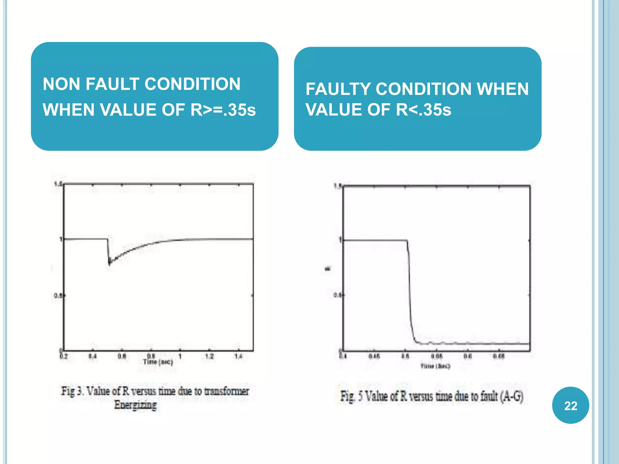
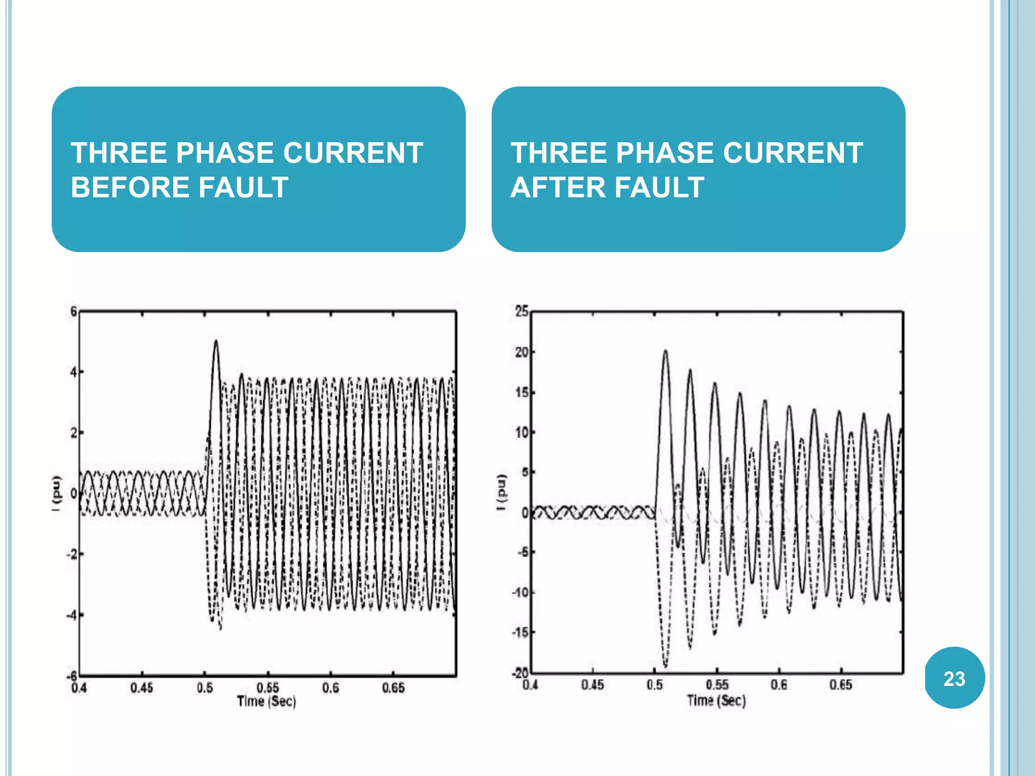
A SEMINAR PRESENTATION
ON
“CONCEPT OF SYMMETRICAL
COMPONENT AS A TECHNIQUE FOR
ANALYSIS OF FAULT AND
IMPROVEMENT OF OVERCURRENT
PROTECTION SCHEME”
Submitted to: Submitted by:
Mr. Ankush Tandon Saurabh Varshney
Mrs. Deepti Arela (10ESKEE106) 1
CONTENT
 INTRODUCTION
 PROTECTION SYSTEM
 SYMMETRICAL COMPONENT
 FAULT
 OVERCURRENT RELAY
 ALGORITHM
 SIMULATION DISTRIBUTION SYSTEM
 RESULTS
 CONCLUSION 2
INTRODUCTION
 Aim of my seminar topic is better
understanding the concept of symmetrical
components for enhancing protection
scheme by providing a practical technology
for understanding and analyzing power
system operation during unbalanced
condition.
3
PROTECTION SYSTEM
What is need of protective system ?
 In order to maintain steady state of
power system by taking correct and
quick remedial action during any faulty
condition.
Properties of a good protective system
Automatic
Quick
Minimum amount of disruption 4
SYMMETRICAL COMPONENT
 Unbalanced systems are difficult to handle.
 It provide balanced analysis of an unbalanced
system
 The unbalanced three phase system can be
transformed into three balanced phasors
 Positive Sequence
 Negative Sequence
 Zero Sequence
5
POSITIVE PHASE SEQUENCE
 Each have the same magnitude.
 Each positive sequence voltage or
current quantity is displaced 120
from one another.
 The positive sequence quantities
have a-b-c, counter clock-wise,
phase rotation.
6
NEGATIVE PHASE SEQUENCE
 Each have the same magnitude.
 Each negative sequence voltage
or current quantity is displaced 120
from one another.
 The negative sequence quantities
have a-c-b, counter clock-wise,
phase rotation.
7
ZERO PHASE SEQUENCE
 Each zero sequence quantity has the same magnitude.
 All three phasor with no angular
displacement between them, all in phase.
8
9
FAULT
o General Causes of fault
 Fault due to lightning
 Tree limbs falling on the line
 Wind damage
 Effects of fault
 Flow of excessive current
 Abnormal voltages
 Induces over voltages on neighbouring
equipments.
 Hazards to human, equipment and animals
TYPES OF FAULTS
• Balanced Faults :
– Three-phase fault
• Unbalanced Faults :
– Single line to ground fault
– Line to line fault
– Double line to ground fault
10
UNBALANCED FAULTS
11
SINGLE LINE TO GROUND FAULT
 The most common type of fault is the single line to
ground fault:
12
13
 The SLG fault can be described by the following
voltage and current relationship:
Ib=0 & Ic=0
Va=IaZf
 The Sequence current can be given as:
LINE TO LINE FAULT
 It occurs when two conductors are short circuited.
 There is no zero sequence component due to
absence of ground return path.
 The positive and negative sequence components
are connected in parallel.
14
DOUBLE LINE TO GROUND FAULT
 In double line to ground fault two line conductors
come in contact with each other and ground .
 The networks are connected in parallel.
 For the zero sequence component it requires to add
an external impedance of Zf+3Zg
15
OVER CURRENT RELAY
 Short-circuit currents are generally several times (5
to 20) full load current. Hence fast fault clearance is
always desirable on short circuits.
 A relay that operates or picks up when it’s current
exceeds a predetermined value (setting value) is
called Over current Relay.
 Over current includes short-circuit protection, and
short circuits can be:
 Phase faults
 Earth faults
 Winding faults
16
TYPES OF OVER CURRENT RELAY
I. Instantaneous Over current (Definite Current)
Relay
II. Definite Time Over current Relay
III. Inverse Time Over current Relay (IDMT
Relay)
i. Moderately Inverse
ii. Very Inverse Time
iii. Extremely Inverse
IV. Directional over current Relay
17
ALGORITHM
 The criterion function for discriminating fault from
non fault switching is defined as follows :
R= |I1|-|I2| / |I1|+|I2|
18
SIMULATED DISTRIBUTION SYSTEM
19
RESULTS
Several non faults events are applied to
this system along with some short circuit
events a different time.
The discrimination of fault from a non
fault event could be done by representing
two cases
 Transformer energizing
 Fault
20
TRANSFORMER ENERGIZING
 Various inrush current condition were simulated.
 Various parameters which have considerable effect
on the characteristic of the current signal were
changed and was analysed.
FAULT
 In this case a single line to ground fault occurs.
21
22
NON FAULT CONDITION
WHEN VALUE OF R>=.35s
FAULTY CONDITION WHEN
VALUE OF R<.35s
23
THREE PHASE CURRENT
BEFORE FAULT
THREE PHASE CURRENT
AFTER FAULT
CONCLUSION
 Simple method of improving over current relays
operation by algorithm, based on different
behaviour of the current amplitudes. Based on
the differences, a criterion function R is defined
such that undesirable operation of the over
current relays to the switching is prevented.
24
THANK YOU
ANY QUERIES?
25

CONCEPT OF SYMMETRICAL COMPONENT AS A TECHNIQUE FOR ANALYSIS OF FAULT AND IMPROVEMENT OF OVERCURRENT PROTECTION SCHEME

  • 1.
    A SEMINAR PRESENTATION ON “CONCEPTOF SYMMETRICAL COMPONENT AS A TECHNIQUE FOR ANALYSIS OF FAULT AND IMPROVEMENT OF OVERCURRENT PROTECTION SCHEME” Submitted to: Submitted by: Mr. Ankush Tandon Saurabh Varshney Mrs. Deepti Arela (10ESKEE106) 1
  • 2.
    CONTENT  INTRODUCTION  PROTECTIONSYSTEM  SYMMETRICAL COMPONENT  FAULT  OVERCURRENT RELAY  ALGORITHM  SIMULATION DISTRIBUTION SYSTEM  RESULTS  CONCLUSION 2
  • 3.
    INTRODUCTION  Aim ofmy seminar topic is better understanding the concept of symmetrical components for enhancing protection scheme by providing a practical technology for understanding and analyzing power system operation during unbalanced condition. 3
  • 4.
    PROTECTION SYSTEM What isneed of protective system ?  In order to maintain steady state of power system by taking correct and quick remedial action during any faulty condition. Properties of a good protective system Automatic Quick Minimum amount of disruption 4
  • 5.
    SYMMETRICAL COMPONENT  Unbalancedsystems are difficult to handle.  It provide balanced analysis of an unbalanced system  The unbalanced three phase system can be transformed into three balanced phasors  Positive Sequence  Negative Sequence  Zero Sequence 5
  • 6.
    POSITIVE PHASE SEQUENCE Each have the same magnitude.  Each positive sequence voltage or current quantity is displaced 120 from one another.  The positive sequence quantities have a-b-c, counter clock-wise, phase rotation. 6
  • 7.
    NEGATIVE PHASE SEQUENCE Each have the same magnitude.  Each negative sequence voltage or current quantity is displaced 120 from one another.  The negative sequence quantities have a-c-b, counter clock-wise, phase rotation. 7
  • 8.
    ZERO PHASE SEQUENCE Each zero sequence quantity has the same magnitude.  All three phasor with no angular displacement between them, all in phase. 8
  • 9.
    9 FAULT o General Causesof fault  Fault due to lightning  Tree limbs falling on the line  Wind damage  Effects of fault  Flow of excessive current  Abnormal voltages  Induces over voltages on neighbouring equipments.  Hazards to human, equipment and animals
  • 10.
    TYPES OF FAULTS •Balanced Faults : – Three-phase fault • Unbalanced Faults : – Single line to ground fault – Line to line fault – Double line to ground fault 10
  • 11.
  • 12.
    SINGLE LINE TOGROUND FAULT  The most common type of fault is the single line to ground fault: 12
  • 13.
    13  The SLGfault can be described by the following voltage and current relationship: Ib=0 & Ic=0 Va=IaZf  The Sequence current can be given as:
  • 14.
    LINE TO LINEFAULT  It occurs when two conductors are short circuited.  There is no zero sequence component due to absence of ground return path.  The positive and negative sequence components are connected in parallel. 14
  • 15.
    DOUBLE LINE TOGROUND FAULT  In double line to ground fault two line conductors come in contact with each other and ground .  The networks are connected in parallel.  For the zero sequence component it requires to add an external impedance of Zf+3Zg 15
  • 16.
    OVER CURRENT RELAY Short-circuit currents are generally several times (5 to 20) full load current. Hence fast fault clearance is always desirable on short circuits.  A relay that operates or picks up when it’s current exceeds a predetermined value (setting value) is called Over current Relay.  Over current includes short-circuit protection, and short circuits can be:  Phase faults  Earth faults  Winding faults 16
  • 17.
    TYPES OF OVERCURRENT RELAY I. Instantaneous Over current (Definite Current) Relay II. Definite Time Over current Relay III. Inverse Time Over current Relay (IDMT Relay) i. Moderately Inverse ii. Very Inverse Time iii. Extremely Inverse IV. Directional over current Relay 17
  • 18.
    ALGORITHM  The criterionfunction for discriminating fault from non fault switching is defined as follows : R= |I1|-|I2| / |I1|+|I2| 18
  • 19.
  • 20.
    RESULTS Several non faultsevents are applied to this system along with some short circuit events a different time. The discrimination of fault from a non fault event could be done by representing two cases  Transformer energizing  Fault 20
  • 21.
    TRANSFORMER ENERGIZING  Variousinrush current condition were simulated.  Various parameters which have considerable effect on the characteristic of the current signal were changed and was analysed. FAULT  In this case a single line to ground fault occurs. 21
  • 22.
    22 NON FAULT CONDITION WHENVALUE OF R>=.35s FAULTY CONDITION WHEN VALUE OF R<.35s
  • 23.
    23 THREE PHASE CURRENT BEFOREFAULT THREE PHASE CURRENT AFTER FAULT
  • 24.
    CONCLUSION  Simple methodof improving over current relays operation by algorithm, based on different behaviour of the current amplitudes. Based on the differences, a criterion function R is defined such that undesirable operation of the over current relays to the switching is prevented. 24
  • 25.