This document provides specifications and dimensions for "NEF" diesel engines including 3 and 4 cylinder configurations. It describes the lubrication, cooling, and turbocharging systems. Dimensions are given for engine blocks, crankshafts, cylinder heads, valves, camshafts, and other components. Torque specifications are also provided for various engine fasteners.
Comprehensive program for Agricultural Finance, the Automotive Sector, and Empowerment . We will define the full scope and provide a detailed two-week plan for identifying strategic partners in each area within Limpopo, including target areas.:
1. Agricultural : Supporting Primary and Secondary Agriculture
• Scope: Provide support solutions to enhance agricultural productivity and sustainability.
• Target Areas: Polokwane, Tzaneen, Thohoyandou, Makhado, and Giyani.
2. Automotive Sector: Partnerships with Mechanics and Panel Beater Shops
• Scope: Develop collaborations with automotive service providers to improve service quality and business operations.
• Target Areas: Polokwane, Lephalale, Mokopane, Phalaborwa, and Bela-Bela.
3. Empowerment : Focusing on Women Empowerment
• Scope: Provide business support support and training to women-owned businesses, promoting economic inclusion.
• Target Areas: Polokwane, Thohoyandou, Musina, Burgersfort, and Louis Trichardt.
We will also prioritize Industrial Economic Zone areas and their priorities.
Sign up on https://profilesmes.online/welcome/
To be eligible:
1. You must have a registered business and operate in Limpopo
2. Generate revenue
3. Sectors : Agriculture ( primary and secondary) and Automative
Women and Youth are encouraged to apply even if you don't fall in those sectors.
5 Warning Signs Your BMW's Intelligent Battery Sensor Needs AttentionBertini's German Motors
IBS monitors and manages your BMW’s battery performance. If it malfunctions, you will have to deal with an array of electrical issues in your vehicle. Recognize warning signs like dimming headlights, frequent battery replacements, and electrical malfunctions to address potential IBS issues promptly.
Fleet management these days is next to impossible without connected vehicle solutions. Why? Well, fleet trackers and accompanying connected vehicle management solutions tend to offer quite a few hard-to-ignore benefits to fleet managers and businesses alike. Let’s check them out!
What Does the PARKTRONIC Inoperative, See Owner's Manual Message Mean for You...Autohaus Service and Sales
Learn what "PARKTRONIC Inoperative, See Owner's Manual" means for your Mercedes-Benz. This message indicates a malfunction in the parking assistance system, potentially due to sensor issues or electrical faults. Prompt attention is crucial to ensure safety and functionality. Follow steps outlined for diagnosis and repair in the owner's manual.
Why Is Your BMW X3 Hood Not Responding To Release CommandsDart Auto
Experiencing difficulty opening your BMW X3's hood? This guide explores potential issues like mechanical obstruction, hood release mechanism failure, electrical problems, and emergency release malfunctions. Troubleshooting tips include basic checks, clearing obstructions, applying pressure, and using the emergency release.
What Exactly Is The Common Rail Direct Injection System & How Does It WorkMotor Cars International
Learn about Common Rail Direct Injection (CRDi) - the revolutionary technology that has made diesel engines more efficient. Explore its workings, advantages like enhanced fuel efficiency and increased power output, along with drawbacks such as complexity and higher initial cost. Compare CRDi with traditional diesel engines and discover why it's the preferred choice for modern engines.
In this presentation, we have discussed a very important feature of BMW X5 cars… the Comfort Access. Things that can significantly limit its functionality. And things that you can try to restore the functionality of such a convenient feature of your vehicle.
𝘼𝙣𝙩𝙞𝙦𝙪𝙚 𝙋𝙡𝙖𝙨𝙩𝙞𝙘 𝙏𝙧𝙖𝙙𝙚𝙧𝙨 𝙞𝙨 𝙫𝙚𝙧𝙮 𝙛𝙖𝙢𝙤𝙪𝙨 𝙛𝙤𝙧 𝙢𝙖𝙣𝙪𝙛𝙖𝙘𝙩𝙪𝙧𝙞𝙣𝙜 𝙩𝙝𝙚𝙞𝙧 𝙥𝙧𝙤𝙙𝙪𝙘𝙩𝙨. 𝙒𝙚 𝙝𝙖𝙫𝙚 𝙖𝙡𝙡 𝙩𝙝𝙚 𝙥𝙡𝙖𝙨𝙩𝙞𝙘 𝙜𝙧𝙖𝙣𝙪𝙡𝙚𝙨 𝙪𝙨𝙚𝙙 𝙞𝙣 𝙖𝙪𝙩𝙤𝙢𝙤𝙩𝙞𝙫𝙚 𝙖𝙣𝙙 𝙖𝙪𝙩𝙤 𝙥𝙖𝙧𝙩𝙨 𝙖𝙣𝙙 𝙖𝙡𝙡 𝙩𝙝𝙚 𝙛𝙖𝙢𝙤𝙪𝙨 𝙘𝙤𝙢𝙥𝙖𝙣𝙞𝙚𝙨 𝙗𝙪𝙮 𝙩𝙝𝙚 𝙜𝙧𝙖𝙣𝙪𝙡𝙚𝙨 𝙛𝙧𝙤𝙢 𝙪𝙨.
Over the 10 years, we have gained a strong foothold in the market due to our range's high quality, competitive prices, and time-lined delivery schedules.
Things to remember while upgrading the brakes of your carjennifermiller8137
Upgrading the brakes of your car? Keep these things in mind before doing so. Additionally, start using an OBD 2 GPS tracker so that you never miss a vehicle maintenance appointment. On top of this, a car GPS tracker will also let you master good driving habits that will let you increase the operational life of your car’s brakes.
Symptoms like intermittent starting and key recognition errors signal potential problems with your Mercedes’ EIS. Use diagnostic steps like error code checks and spare key tests. Professional diagnosis and solutions like EIS replacement ensure safe driving. Consult a qualified technician for accurate diagnosis and repair.
"Trans Failsafe Prog" on your BMW X5 indicates potential transmission issues requiring immediate action. This safety feature activates in response to abnormalities like low fluid levels, leaks, faulty sensors, electrical or mechanical failures, and overheating.
Ever been troubled by the blinking sign and didn’t know what to do?
Here’s a handy guide to dashboard symbols so that you’ll never be confused again!
Save them for later and save the trouble!
1. A3.2 Nectis 207 – 12.2005 – GB
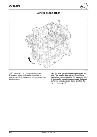
General specification
103vfm00 Fig. 1
"NEF" engines are 3 or 4 cylinder diesel units with
2 valves per cylinder, and may be atmospheric or
turbo-charged. They are equipped with mechanical rotary
injection pumps.
N.B.: The data, characteristics and outputs are only
valid if the installer observes the relevant Iveco
installation recommendations. Any equipment fitted
by the installer must also always respect the torque
and power outputs and rpm figures for which the
engine was designed.
2. A3.8 Nectis 207 – 12.2005 – GB
Lubrication
Operation
The pressurised lubrication system uses a lobe oil pump
located at the front of the block, driven by the splined ring
attached to the crankshaft cone. Oil is pumped from the
crankcase to the crankshaft, the camshaft and the
cylinder head (oil cooler, turbocharger).
Oil system layout (3-cylinder engine)
221vfm00 Fig. 3
Nomenclature
177 Turbocharger oil return line.
178 Oil filter.
179 Oil cooler element.
180 Oil cooler.
181 Oil pump.
Oil pressure feed.
Oil gravity return route.
177
178
179
180
181
4. A3.10 Nectis 207 – 12.2005 – GB
Cooling
Operation
The pressurised closed circuit engine cooling system has
the following components:
• Expansion tank.
• Radiator, to dissipate the heat extracted from the
engine by the coolant fluid.
• Visco-static cooling fan to increase the radiator's heat
dissipation capability, that also forms part of the engine's
specific build.
– An oil cooler to cool the lubricant oil
– A centrifugal-type water pump located at the front of the
engine block.
– A thermostat that controls the circulation of the coolant
fluid.
Cooling (3-cylinder engine)
251vfm05 Fig. 5
Nomenclature
A Radiator inlet.
B Radiator outlet.
Coolant leaving the thermostat.
Coolant recirculating within the engine.
Coolant entering the water pump.
A
B
5. Nectis 207 – 12.2005 – GB A3.11
Cooling
Cooling system (4-cylinder engine)
251vfm06 Fig. 6
Nomenclature
A Radiator inlet.
B Radiator outlet.
Coolant leaving the thermostat.
Coolant recirculating within the engine.
Coolant entering the water pump.
A
B
6. A3.12 Nectis 207 – 12.2005 – GB
Turbocharger
Operation
Turbo-charged version of the engine
167vfm00 Fig. 7
The air intake system consists of an air filter and an
exhaust-driven compressor (turbocharger).
Air from the compressor outlet is fed directly to the inlet
manifold.
Nomenclature
4 Exhaust.
209 Air filter.
210 Turbocharger. A 3 cylinder version.
B 4 cylinder version.
210
4
210
209
209
A
B
4
8. A3.14 Nectis 207 – 12.2005 – GB
DIMENSIONS
Type Atmospheric Turbo-charged
Engine block and crank assembly (mm)
Piston ring gap in cylinder
liner:
X1
X2
X3
0,25 – 0,55
0,30 – 0,55
0,30 – 0,55
0,30 – 0,40
0,60 – 0,80
0,30 – 0,55
Connecting rod
Bush housing in small end (ø
1)
40,987 – 41,013
Big-end bearing shell housing
(ø 2)
72,987 – 73,013
Small end bush dimensions
External (ø 4)
Internal (ø 3)
40,987 – 41,013
38,019 – 38,033
Replacement big-end bearing
shells supplied (S)
1,955 – 1,968
Gudgeon pin clearance - bush 0,019 – 0,039
Big-end bearing shells
(repair size)
0,250 – 0,500
Crankshaft
Main journals (ø 1) 82,990 – 83,010
Big-end journals (ø 2) 68,987 – 69,013
X1
X2
X3
ø 1
ø 2
S
ø 4
ø 3
ø 1 ø 2
9. Nectis 207 – 12.2005 – GB A3.15
DIMENSIONS
Type Atmospheric Turbo-charged
Engine block and crank assembly (mm)
Crankshaft main bearing
shells (S1)
2,456 – 2,464
Big-end bearing shells (S2) 1,955 – 1,968
Engine block
Main bearing
N° 1 - 4 (ø 3)
N° 2 - 3 (ø 3)
87,982 – 88,008
87,977 – 88,013
Set of bearing shells - main
bearing
N° 1 - 4
N° 2 - 3
0,064 – 0,095
0,059 – 0,100
Set of big-end bearing shells 0,033 – 0,041
Main bearing shells (repair
size)
Big-end bearing shells (repair
size)
+ 0,250 ; + 0,500
Main bearing with thrust
shoulder (X1)
37,475 – 37,550
Main bearing with thrust
shoulder (X2)
31,730 – 32,280
Thrust bearing shells (X3) 37,28 – 37,38
Crankshaft thrust bearing end
float
0,095 – 0,270
S1 S2
ø 3
X1
X2
X3
10. A3.16 Nectis 207 – 12.2005 – GB
DIMENSIONS
Type Atmospheric Turbo-charged
Cylinder head - valvegear (mm)
Valve
Valve guide housings in
cylinder head
See detail under "valves"
Valves: See detail under "valves"
Clearance between valve
stem and valve guide
0,039 – 0,079
Valve head recess below
cylinder head face
Intake (X)
0,336 – 1,072
Exhaust (X)
0,104 – 0,840
X
11. Nectis 207 – 12.2005 – GB A3.17
DIMENSIONS
Type Atmospheric Turbo-charged
Cylinder head - valvegear (mm)
Valve spring height
Spring unloaded: H 63,50
Spring under a load of:
32,9 daN (H1) 49,02
64,1 daN (H2) 38,20
Injector
Injector protrusion (X) Not adjustable
Camshaft
Camshaft bearing housings:
– Rear bearing diameter C
(3-cylinder engine).
– Rear bearing diameter C
and front bearing diameter A
(4-cylinder engine).
59,222 – 59,248
Camshaft bearing housings:
– 2 intermediate bearings
diameter B and front bearing
diameter A
(3-cylinder engine).
– 3 intermediate bearings
diameter B
(4-cylinder engine).
54,089 – 54,139
Camshaft bearings:
ø 53,995 – 54,045
Bearing internal diameter (ø) 54,083 – 54,147
H H1
H2
X
ø A ø B ø C
ø
ø
12. A3.18 Nectis 207 – 12.2005 – GB
DIMENSIONS
Type Atmospheric Turbo-charged
Cylinder head - valvegear (mm)
Clearance between bearings
and camshaft
0,038 – 0,152
Clearance between bearings
and engine block
0,044 – 0,144
Effective valve lift:
Exhaust (H) 11,02
Intake (H) 10,74
Cam followers
Cam follower housing in
block (ø 1)
16,000 – 16,030
Cam follower external
diameter:
Ø2 15,929 – 15,959
Ø3 15,965 – 15,980
Clearance between cam
follower and housing
0,020 – 0,065
Rockers
Rocker shaft (ø 1) 18,963 – 18,975
Rockers (ø 2) 19,000 – 19,026
Clearance between rockers
and rocker shaft
0,025 – 0,063
Adjusting the valve rockers
Inlet valves x (mm) 0,25 ± 0,05
Exhaust valves x (mm) 0,50 ± 0,05
H
ø 1
ø 2
14 32 50
ø 2
ø 3
ø 1
ø 2
X
15. Nectis 207 – 12.2005 – GB A3.21
Torque settings
Front chassis / engine link
A. 39 daN.m (4 M20 nuts).
Engine/transmission link
B. 8 daN.m + Frenetanch (242)
(4 screws HM12x125-65).
C. Locating pin.
D. 8 daN.m + Frenetanch (242)
(8 screws HM12x175-50).
103vfm02 Fig. 12
103vfm03 Fig. 13
A
A
B
C
D D
B
C
D D
17. Nectis 207 – 12.2005 – GB A3.23
Torque settings
See Figure 14.
Ref Attachment – Phase
3 cylinders 4 cylinders
Torque in daN.m
1 M8 x 1,25 x 10 1,5 ± 0,3
2
M8 x 1,25 x 50
2,4 ± 0,4
M8 x 1,25 x 35
3
M10 x 1,50 x 40/50 5 ± 0,5
M10 x 1,50 x 70/100 7 ± 0,5
4 (M8 x 1,25 x 20) x 2
2,4 ± 0,4
5 M8 x 1,25
6
M12 x 1,75 x 70 (2 phases) 5 ± 0,5 + 90°
M12 x 1,75 x 140 (3 phases) 4 ± 0,5 + 90° + 90°
M12 x 1,75 x 180 (3 phases) 7 ± 0,5 + 90° + 90°
7 M8 x 1,25
2,4 ± 0,4
8 M8 x 1,25 x 25
9 M8 x 1,25 x 100
10 M8 x 1,25 x 40
11 (M8 x 1,25 x 50) x 4
12 (M10 x 1,50 x 35) x 4
4,5 ± 0,5
13 (M10 x 1,50 x 25) x 2
14
(M12 x 1,15 x 75) x 6
First phase 5 ± 0,5
Second phase 90° ± 5°
15
(M12 x 1,75 x 100) x 2
8,0 ± 1,0
(M12 x 1,75 x 78) x 14
(M16 x 1,50 x 80) x 3
20 ± 2
(M16 x 1,50 x 100) x 2
16
(M12 x 1,25 x 31) x 8
First phase 3,0 ± 0,5
Second phase 60° ± 5°
17 Nut (rocker adjuster screw) 0,5 ± 0,1
18 M10 x 4 Nut 4,3 ± 0,6
19 Hydraulic coupling (M12 x 1,5) 3,5 ± 0,5
20 M8 x 3 Nut 2,4 ± 0,4
18. A3.24 Nectis 207 – 12.2005 – GB
Torque settings
Ref Attachment – Phase
3 cylinders 4 cylinders
Torque in daN.m
21
M10 x 1,5 x 40
4,5 ± 0,5
M10 x 1,5 x 130
22 (M10 x 1,50 x 35) x 3 4,3 ± 0,5
23
M12 Screw
First phase 5 ± 0,6
Second phase 8 ± 0,62
Third phase 90° ± 5°
24 M8 Screw 2,4 ± 0,4
25 (M8 x 1,25 x 35) x 6 3,6 ± 0,4
26
M11 Screw
First phase 6 ± 0,5
Second phase 60° ± 5°
27 M8 x 1,25 x 25 2,4 ± 0,4
28 (M10 x 1,50) x 8 3,2 ± 0,3
29 (M8 x 1,25 x 65) x 3
2,4 ± 0,4
30 (M8 x 1,25 x 35) x 12
31 (M10 x 1,5 x 50) x 3 4,8 ± 0,5
32 Engine temperature sensor 2,5 ± 0,5
33 Temperature sensor 3 ± 0,2
34 Oil pressure sensor 3,5 ± 0,2
35 Drain plug 5 ± 0,5
19. Nectis 207 – 12.2005 – GB A3.25
Checks/adjustments
Compression
N.B.: before starting the test, make sure that the
battery is fully charged and that the injector area is
perfectly clean.
– Start the engine and let it idle for 10 to 15 minutes to
achieve an oil temperature of 40 °C.
– Remove the injectors.
– Fit the dummy injector n° 00 11 301 120 (230) with
compression tester n° 60 05 721 169 (231) in place of
the injector from n° 1 cylinder (fan end).
– Disconect the engine shut down solenoid valve from
the injector pump.
– Connect the compression tester leads to the terminal
on the starter solenoid (232) with the red clip (233) to the
battery or the starter.
– Turn the engine on the starter by pressing button (234)
until the needle fully stabilises.
– Move ring (235) to depressurise the unit until the
needle returns to zero.
– Advance the record sheet (236) by pressing
button (237) on the side of the unit.
– Repeat the test on the remaining cylinders.
The compression should be between 18 and 22 bar.
Engine oil pressure
Remove the oil pressure sensor and fit pressure gauge
n° 77 01 388 204 (9) to the block in its place (Fig. 16).
Before checking the pressure, warm up the engine.
Engine oil pressure should be between 0,7 and 3,5 bar.
103vfm12 Fig. 15
103vfm06 Fig. 16
230
235
232
233
234
231
237
236
9
20. A3.26 Nectis 207 – 12.2005 – GB
Checks/adjustments
Turbocharger pressure
See chapter "A1".
Pressure test point for the turbocharger without mixture
limiter (Fig. 17).
103vfm13 Fig. 17
Pressure test point for the turbocharger with mixture
limiter.
103vfm14 Fig. 18
21. Thank you very much for
your reading. Please Click
Here. Then Get COMPLETE
MANUAL. NO WAITING
NOTE:
If there is no response to
click on the link above,
please download the PDF
document first and then
click on it.
22. Nectis 207 – 12.2005 – GB A3.27
Checks/adjustments
N.B.: To reduce the time taken to adjust the
tappet/valve clearance, proceed as follows: Position
cylinder n° 1 at the top of the compression stroke and
adjust the valves marked with an asterisk in the
following table.
• 3-cylinder engine
N.B.: Rotate the crankshaft 360° and adjust the valves
marked with an asterisk in the table.
Valves
Valve clearance
Condition: Engine cold.
– Turn the flywheel in the normal rotational sense until
piston n° 1 (radiator end) is at top dead centre (TDC). To
determine TDC position, see chapter A2 :
"Remove/Refit". "Injector Pump".
– Adjust clearance between rocker arms and valve
stems. The setting is:
– Inlet valves: 0,25 ± 0,05 mm.
– Exhaust valves: 0,50 ± 0,05 mm.
131vfm04 Fig. 19
13
11
12
Cylinder N° 1 2 3
Intake * * —
Exhaust * — *
Cylinder N° 1 2 3
Intake — — *
Exhaust — * —
23. A3.28 Nectis 207 – 12.2005 – GB
Checks/adjustments
• 4-cylinder engine
Note: Turn the crankshaft through 360° and adjust the
valves marked with an asterisk in the table.
Valve lift (Engine cold)
N.B.: Measuring valve lift enables any wear in the cam
to be detected.
1. Rotate the engine and position the valves as described
the the "valve clearance" paragraph.
2. Reduce valve clearance to zero.
3. Place a dial gauge on the valve spring cup or on the
valve cap and then set to "0".
4. Turn the engine until the dial gauge reaches a
maximum value showing that the valve is fully open.
Check the values against the specifications at the
beginning of this chapter.
5. Measure valve lift as explained, then reset the tappet
clearance.
6. If the specification figures are not met, remove the
camshaft and check its condition.
Cylinder N° 1 2 3 4
Intake * * — —
Exhaust * — * —
Cylinder N° 1 2 3 4
Intake — — * *
Exhaust — * — *
24. Nectis 207 – 12.2005 – GB A3.29
Checks/adjustments
Dimensional check
Checking and repairing the valves
– Remove all carbon deposits using the recommended
wire brush.
– Check that there are no signs of seizure, cracking or
burning on the valves.
131vfm06 Fig. 20
Using a micrometer gauge (14) measure the valve stem
diameter (15). Refer to the chapter "Dimensional
specifications".
131vfm07 Fig. 21
Clearance between stem and guide and
valve centering
These checks are carried out using a dial gauge (18) with
magnetic stand positioned as shown. The play should be
between 0,052 and 0,092 mm. Turn the valve (15) and
check that the play does not exceed 0,03 mm.
131vfm08 Fig. 22
15
14
18
15