The document provides instructions for inspecting and servicing various components of the cylinder head and valves for an Arion 640-510 engine, including removing and refitting the cylinder head cover, thermostat cover and manifold, alternator, turbocharger, exhaust manifold, EGR cooler and ducts, and other related components. Dimensions, specifications, and torque values are provided for components like the valves, springs, rockers, valve guides, and more. Detailed diagrams illustrate the procedures.
Claas arion 600 (type a19) tractor service repair manualfjkskedmme
1. The document provides instructions for inspecting, measuring, and removing/refitting various components of the cylinder head and valves of an Arion 640-510 engine, including the valve bridges, rocker pins, rockers, valves, springs, cylinder head, guides, seats, and turbocharger.
2. Dimensions and specifications are provided for comparing wear limits and clearances. Instructions specify cleaning, marking, and replacing worn parts.
3. The removal and refitting process for several accessories is described, including the alternator, viscous coupling, fan hub, and turbocharger. Torques and directions are noted.
Claas arion 540 510 (type a18) tractor service repair manualfjskeazqkkdmme
The document provides instructions for servicing components of the cylinder head and valves for an Arion 640-510 engine. It describes how to inspect, measure, and replace various parts including the cylinder head, valves, valve guides, springs, rockers, and related components. Procedures are outlined for removing and refitting the cylinder head cover, thermostat cover, exhaust manifold, turbocharger, and other parts. Tolerances and specifications are provided to check wear limits and clearances.
Claas arion 600 c (type a20) tractor service repair manualfjkskedmme
1) The document provides instructions for inspecting, measuring, and removing/refitting various cylinder head and valve components of an Arion 630-610 C engine, including the cylinder head, valves, rockers, turbocharger, alternator, fan hub, and exhaust manifold.
2) Specified values are provided for dimensions, clearances, and torque specifications when removing or tightening components.
3) Detailed steps and diagrams illustrate the inspection, measurement, removal and refitting processes for each component. Cautions and notes are included throughout.
Claas arion 540 510 (type a18) tractor service repair manualikdkkdmdmdm
The document provides instructions for servicing components of the cylinder head and valves for an Arion 640-510 engine. It describes how to inspect, measure, and replace various parts including the cylinder head, valves, valve guides, springs, rockers, and related components. Procedures are outlined for removing and refitting the cylinder head cover, thermostat cover and manifold, exhaust manifold, turbocharger, and other parts. Tolerances and specifications are provided to check wear limits and clearances.
Claas arion 540 510 (type a18) tractor service repair manualfhsejkdkmen
The document provides instructions for servicing components of the cylinder head and valves for an Arion 640-510 engine. It describes how to inspect, measure, and replace various parts including the cylinder head, valves, valve guides, springs, rockers, and related components. Procedures are outlined for removing and refitting the cylinder head cover, thermostat cover and manifold, exhaust manifold, turbocharger, and other parts. Tolerances and specifications are provided to check wear limits and clearances.
Mc cormick mtx series (2002 2007) - mtx3 - mtx135 b power tractor service rep...fjskeazqkkdmme
This document provides parts listings and descriptions for engine, cooling system, hydraulic system, air intake, and exhaust components for MTX Series tractors from 2002-2007, including the MTX3, MTX120, MTX135, and MTX150 models. Over 50 individual parts are listed along with quantities required and additional identifying information. Replacement and technical specifications are also provided at the end.
Mc cormick mtx series (2002 2007) - mtx3 - mtx120 b power tractor service rep...fjskeazqkkdmme
This document provides parts lists and diagrams for engine, cooling system, hydraulic system, air intake, and exhaust components for MTX Series tractors from 2002-2007, including the MTX3, MTX120, MTX135, and MTX150 models. It lists over 50 individual part numbers, quantities, and brief descriptions for replacement of components.
Mc cormick mc power4 tier 3 restyling (2009 2013) - rpb2 - 130 tractor servic...fjskeazqkkdmme
This document contains parts lists and component information for engines. It includes lists of components with part numbers, serial number ranges they are applicable to, and labels like "engine" or "pump". Replacement parts are noted, along with labels for components like "cylinder head" or "piston". The parts are associated with McCormick Power4 Tier 3 engines from 2009-2013.
Mc cormick mc power4 tier 3 restyling (2009 2013) - rpb2 - 115 tractor servic...fjskeazqkkdmme
This document provides parts information for various engine components. It includes lists of parts with identification numbers, quantities and reference numbers. The parts listed are for engines, pumps, cylinders, pistons, rods and other internal engine components. Next to each part is information on whether it is serviced or requires replacement, and serial number ranges that part is applicable to.
Mc cormick mc power4 tier 3 restyling (2009 2013) - rpb2 - 110 tractor servic...fjskeazqkkdmme
These documents provide parts lists and component information for Perkins engines. They include lists of engine parts with item numbers, part names and numbers, quantities, and notes. References are made to other documents for additional information on components that are part of larger assemblies.
Mc cormick mc power4 tier 3 (2008 2009) - rpb1 - 105110 tractor service repai...fjskeazqkkdmme
This document contains parts listings and component information for an engine. It lists 22 individual parts with reference numbers, descriptions, and other identifying information. It indicates that this is a component of a larger assembly and provides instructions on references, replacements, and ordering of parts. The parts listed are for various engine systems like the cylinder head, injection pump, rocker assembly, and sump.
Mc cormick mc power4 tier 3 (2008 2009) - rpb1 - 130 tractor service repair m...fjskeazqkkdmme
This document provides component part listings and replacement kit information for various engine systems. It includes lists of parts for the cylinder head, fuel pump, pistons, crankshaft, flywheel, and other engine subassemblies. Each part is identified by number and name, and replacement kits are specified. The document also provides engine serial number ranges for some component assemblies.
Mc cormick mc power4 tier 3 (2008 2009) - rpb1 - 115 tractor service repair m...fjskeazqkkdmme
This document contains a list of components that make up various engine assemblies. Each component is listed with its reference number, description, and notes indicating whether it is serviced or replaced as part of an overhaul. The document also provides assembly level information to identify the components' context within larger assemblies.
Mc cormick mc common rail tier 3 (2007 2008) - mc01 - 115 tractor service rep...fjskeazqkkdmme
The document provides parts information for engine components. It lists part numbers, descriptions, and specifies that the parts are for McCormick tractors with a Common Rail Tier 3 engine from 2007-2008. It also notes that some parts are not serviced and to order replacements, and includes the engine serial number range for applicability of certain parts.
Mc cormick mb series tier 2 (limited market) (2005 ) - rt61 - mb85 tractor s...fjskeazqkkdmme
This document contains parts information for engine components. It lists part numbers, descriptions, application details and indicates whether parts are for replacement or repair. It also provides engine serial number ranges for some components and indicates color coding for similar parts. The document contains technical specifications for pistons, rods, bearings, valves, springs, seals and other engine parts.
Mc cormick mb series tier 2 (limited market) (2005 ) - rt61 - mb55 tractor s...fjskeazqkkdmme
This document contains parts information for an engine, including part numbers, descriptions, and other technical details. It lists individual engine components and assemblies with replacement part numbers. Notes indicate some parts are only available as part of assemblies and not as individual components.
Mc cormick g max tier 3 new cab (2012- ) - rp75 - 165 tractor service repair ...fjskeazqkkdmme
This document provides parts information for an engine, including:
1. Lists of parts with reference numbers and descriptions in multiple pages of diagrams and tables.
2. Information on replacement parts, alternatives, and shims for certain components.
3. References to other documents for additional information on some parts.
Mc cormick g max tier 3 new cab (2012- ) - rp75 - 145 tractor service repair ...fjskeazqkkdmme
This document provides exploded views and part lists for engine components. It includes 3 pages summarizing parts for the crankcase, 3 pages for the cylinder head, and additional pages for other engine systems like the valve train, turbocharger, and fuel system. Each component lists the part number, description, and quantity used. Reference numbers link between diagrams and callouts for replacement parts.
Mc cormick g max tier 3 new cab (2012- ) - rp75 - 135 tractor service repair ...fjskeazqkkdmme
This document provides parts information for an engine. It includes a list of over 100 individual engine parts with descriptions and part numbers. The parts are grouped into categories like the crankcase, head, valves, pistons, and others. Additional information provided includes markets the part is applicable for and replacement/alternative parts.
Massey ferguson mf8260 lst tractor parts catalogue manualfjskeazqkkdmme
This document provides parts information for an MF 8260 LST tractor from 2001, including:
- The engine and various engine parts like the clutch, fan, alternator, belts, starter motor.
- Detailed listings of individual parts with part numbers, quantities, descriptions and other details.
- Specifications and illustrations for components like the cylinder block, pistons, valves, gaskets, seals and other internal engine parts.
- Information is provided on which part numbers apply to different serial number ranges for the tractor.
In summary, this document contains highly detailed technical specifications and exploded diagrams of engine parts for an MF 8260 tractor from 2001. It provides the part numbers, descriptions
Massey ferguson mf8250 tractor parts catalogue manualfjskeazqkkdmme
This document provides parts information for the engine of a Massey Ferguson 8250 tractor. It includes detailed lists and diagrams of engine parts, labeled with part numbers. The parts are grouped into sections covering the cylinder block, timing gear housing, flywheel housing, crankshaft/pistons/connecting rods, and valve mechanism/camshaft. Each item lists the part number, quantity, description, and any additional comments or specifications. This level of detail is intended to support maintenance and repair of the tractor engine.
Massey ferguson mf8180 tractor parts catalogue manualfjskeazqkkdmme
This document contains parts lists and diagrams for various components of a Massey Ferguson 8180 tractor, including the engine, alternator, starter, heater block, cylinder block, cylinder block equipment, timing gear housing, flywheel housing, crankshaft, pistons, connecting rods, and main bearings. Over 150 individual part numbers are listed along with quantities and descriptions. Diagrams visually depict the components and their assembly.
Kubota b2910 hsd tractor parts catalogue manualfjskeazqkkdmme
This document provides part numbers and descriptions for a crankcase. It includes the following information for each part: reference number, part number, description, quantity used, applicable serial number range, interchangeability code, remarks, weight in kilograms, and weight in pounds. The serial number range indicates whether a part is compatible with equipment above or below a certain serial number.
Kubota b2710 hsd tractor parts catalogue manualfjskeazqkkdmme
This document provides instructions for using a parts book and summarizes the column headings found on parts book pages. It explains that the column headings include the reference number, part number, description, quantity, serial number range information, interchangeability codes, and remarks. It also provides notes about country codes that may be included to indicate if a part is different for certain countries.
Kubota b2410 hse tractor parts catalogue manualfjskeazqkkdmme
The document provides instructions and part numbers for a parts book. It defines the column headings used on part number pages, including the reference number, part number, description, quantity, serial number range and interchangeability. It also notes country codes that may be included and their meanings.
Komatsu wa200 pz 6 wheel loader service repair manual snh00051 and upfjskeazqkkdmme
This document provides information about Komatsu wheel loaders, including:
- The shop manual covers models WA200-6 and WA200PZ-6.
- Sections include specifications, maintenance procedures, testing and adjustments, troubleshooting, and electrical systems.
- Technical details are provided for the engine, power train, steering, brakes, hydraulics, work equipment and electrical systems.
- Testing, adjustment and troubleshooting procedures are described for components like the engine, hydraulics, electrical systems and more.
Cub cadet 3186 tractor service repair manualfjskeazqkkdmme
The document is a service manual for the Cub Cadet 3000 series. It contains sections on pre-delivery checks, engineering updates for 1999 models, procedures for removing and replacing parts like fenders and hydraulic cylinders, and troubleshooting hydraulic and electrical systems. The table of contents lists 18 sections that provide step-by-step instructions for maintenance, repairs, and inspections of the tractor.
Cub cadet 3185 tractor service repair manualfjskeazqkkdmme
The document is a service manual for the Cub Cadet 3000 series. It contains sections on pre-delivery checks, engineering updates for 1999 models, procedures for removing and replacing parts like fenders and hydraulic cylinders, and troubleshooting hydraulic and electrical systems. The table of contents lists 18 sections that provide step-by-step instructions for maintenance, repairs, and inspections.
The Octavia range embodies the design trend of the Škoda brand: a fusion of
aesthetics, safety and practicality. Whether you see the car as a whole or step
closer and explore its unique features, the Octavia range radiates with the
harmony of functionality and emotion
Welcome to ASP Cranes, your trusted partner for crane solutions in Raipur, Chhattisgarh! With years of experience and a commitment to excellence, we offer a comprehensive range of crane services tailored to meet your lifting and material handling needs.
At ASP Cranes, we understand the importance of reliable and efficient crane operations in various industries, from construction and manufacturing to logistics and infrastructure development. That's why we strive to deliver top-notch solutions that enhance productivity, safety, and cost-effectiveness for our clients.
Our services include:
Crane Rental: Whether you need a crawler crane for heavy lifting or a hydraulic crane for versatile operations, we have a diverse fleet of well-maintained cranes available for rent. Our rental options are flexible and can be customized to suit your project requirements.
Crane Sales: Looking to invest in a crane for your business? We offer a wide selection of new and used cranes from leading manufacturers, ensuring you find the perfect equipment to match your needs and budget.
Crane Maintenance and Repair: To ensure optimal performance and safety, regular maintenance and timely repairs are essential for cranes. Our team of skilled technicians provides comprehensive maintenance and repair services to keep your equipment running smoothly and minimize downtime.
Crane Operator Training: Proper training is crucial for safe and efficient crane operation. We offer specialized training programs conducted by certified instructors to equip operators with the skills and knowledge they need to handle cranes effectively.
Custom Solutions: We understand that every project is unique, which is why we offer custom crane solutions tailored to your specific requirements. Whether you need modifications, attachments, or specialized equipment, we can design and implement solutions that meet your needs.
At ASP Cranes, customer satisfaction is our top priority. We are dedicated to delivering reliable, cost-effective, and innovative crane solutions that exceed expectations. Contact us today to learn more about our services and how we can support your project in Raipur, Chhattisgarh, and beyond. Let ASP Cranes be your trusted partner for all your crane needs!
Implementing ELDs or Electronic Logging Devices is slowly but surely becoming the norm in fleet management. Why? Well, integrating ELDs and associated connected vehicle solutions like fleet tracking devices lets businesses and their in-house fleet managers reap several benefits. Check out the post below to learn more.
What Could Be Behind Your Mercedes Sprinter's Power Loss on Uphill RoadsSprinter Gurus
Unlock the secrets behind your Mercedes Sprinter's uphill power loss with our comprehensive presentation. From fuel filter blockages to turbocharger troubles, we uncover the culprits and empower you to reclaim your vehicle's peak performance. Conquer every ascent with confidence and ensure a thrilling journey every time.
Ever been troubled by the blinking sign and didn’t know what to do?
Here’s a handy guide to dashboard symbols so that you’ll never be confused again!
Save them for later and save the trouble!
Claas arion 640 (type a19) tractor service repair manual
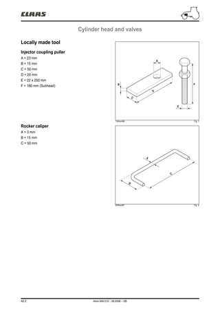
1. A2.2 Arion 640-510 – 09.2008 – GB
Cylinder head and valves
Locally made tool
Injector coupling puller
A = 23 mm
B = 15 mm
C = 50 mm
D = 20 mm
E = 22 x 250 mm
F = 180 mm (Subhead)
134hsm06 Fig. 1
Rocker caliper
A = 3 mm
B = 15 mm
C = 50 mm
324hsm97 Fig. 2
F
E
C
D
B
A
C
B
A
2. Arion 640-510 – 09.2008 – GB A2.3
Cylinder head and valves
Inspecting valve bridges
– Clean the valve bridges and check they are not
damaged.
– Measure the boreholes of the valve bridges (A) and
check that the gap between one bore and another does
not exceed the value specified.
Maximum gap between bores...............................0,1 mm
134hsm07 Fig. 3
Inspecting the rocker pin
Note: Mark the location of the rockers when removing
in order to facilitate refitting.
– Remove the caps (A) only to change them or to clean
the rocker axis.
– Disassemble and search for traces of wear or damage.
Change all parts which are damaged or non compliant
with specifications.
134hsm08 Fig. 4
Outer diameter of the axis ................19,962 - 20,038 mm
Wear limit..........................................................19,91 mm
134hsm09 Fig. 5
A
A
3. A2.4 Arion 640-510 – 09.2008 – GB
Cylinder head and valves
Inner diameter of the rocker..............20,065 - 20,115 mm
Wear limit..........................................................20,16 mm
134hsm10 Fig. 6
Inspecting the rockers
– Remove and clean the rockers (A). Mark them for
refitting.
134hsm11 Fig. 7
– Measure the outer diameter of the rockers. If it is below
the value recommended, change it.
Specified value:
Rocker outer diameter ..........................31,61 - 31,64 mm
– Measure rocker clearance in the bore.
Specified value:
Bore diameter
(in the block) .........................................31,70 - 31,75 mm
Rocker and borehole clearance................0,06 - 0,13 mm
– Check the head on the rocker journals. If it is flat or
concave, change the rocker and check the camshaft
lobes.
134hsm12 Fig. 8
A
4. Arion 640-510 – 09.2008 – GB A2.5
Cylinder head and valves
Measuring valve shrinkage
Measurements must be made at a maximum distance of
3 mm from the edge of the valve head.
– Compare the measurements (A) between the 2 inlet
and exhaust valves. Check that the gap does not exceed
the value specified.
Note: If a cylinder has uneven valve wear, check the
gap of boreholes on valve bridges.
Specified value:
• Intake valve
Shrinkage in the cylinder head .................0,77 - 1,27 mm
Wear limit............................................................1,77 mm
• Exhaust valve
Shrinkage in the cylinder head .................0,81 - 1,31 mm
Wear limit............................................................1,81 mm
Maximum gap for a pair of valves per
cylinder........................ .........................................0,3 mm
131hsm33 Fig. 9
Cylinder head flatness
– Check cylinder head flatness using a precision rule and
a set of shims. Check along the length, across and in
diagonal in several locations.
Specified value:
Maximum acceptable straightness error over the entire
length or width ....................................................0,08 mm
Maximum acceptable straightness error over the entire
length of 150 mm................................................0,03 mm
Note: If the straightness error exceeds the values
specified, rectify or change the cylinder head.
132hsm05 Fig. 10
A
5. A2.6 Arion 640-510 – 09.2008 – GB
Cylinder head and valves
Measuring cylinder head thickness
– Measure the cylinder head's thickness between the
parting of the cylinder head cover riser and the
combustion reaching.
Specified value:
New cylinder head ............................104,87 - 105,13 mm
Minimum acceptable cylinder head thickness 104,24 mm
Maximum ripple depth ......................................0,012 mm
Maximum material which can be removed when rectifying
0,76 mm
Note: If the cylinder head thickness is below the
minimum acceptable, do not rectify. Change the
cylinder head.
Important: Check cylinder head flatness using a
precision rule and a set of shims.
Valve guide measurement
– Measure wear on the valve guides.
Specified value:
Diameter of the valve guide borehole...............................
7,025 - 7,051 mm
Clearance between rod and guide
– Intake.................................................0,012 - 0,064 mm
– Exhaust..............................................0,025 - 0,077 mm
Wear limit between stem and guide....................0,15 mm
132hsm06 Fig. 11
132hsm07 Fig. 12
6. Arion 640-510 – 09.2008 – GB A2.7
Cylinder head and valves
Measuring the valve seat bore in the
cylinder head
If the dimensions of the boreholes do not comply with the
values specified, machine the cylinder head according to
the values.
Specified value:
• Seat insert valve borehole
– Exhaust
A. 36,436 - 36,462 mm.
B. Reference 2,34 mm.
C. 8,715 - 8,785 mm.
D. 38 - 42°.
E. Maximum radius 0,5 mm.
– Intake
A. 37,436 - 37,462 mm.
B. Reference 2,8 mm.
C. 9,715 - 9,785 mm.
D. 38 - 42°.
E. Maximum radius 0,5 mm.
Changing the outer diameter of seat insert valve
boreholes.
– Exhaust..........................................36,487 - 36,513 mm
– Intake.............................................37,487 - 37,513 mm
Measuring the valve springs
Check spring tension using a spring compression device.
Idle length .........................................................46,15 mm
Specified value:
Height comrpessed, spring tension............................. .46
mm from 18 to 27 N
Spring compressed at 166 N ............................37,21 mm
Spring compressed at 356 N ............................27,01 mm
132hsm08 Fig. 13
131hsm34 Fig. 14
7. A2.8 Arion 640-510 – 09.2008 – GB
Cylinder head and valves
Measuring the valves
– Clean and inspect the valves, the valve stems, the tips
of the stems and the retaining groove (A).
Specified value:
• Valve head diameter
– Intake.................................................36,87 - 37,13 mm
– Exhaust..............................................35,87 - 36,13 mm
Note: The intake valves have a larger outer diameter
and are recognized by a raised letter "O".
131hsm35 Fig. 15
131hsm36 Fig. 16
• Valve stem diameter
– Intake.................................................6,987 - 7,013 mm
– Exhaust..............................................6,984 - 7,000 mm
• Maximum ovalization
– Inlet and exhaust ...........................................0,038 mm
131hsm37 Fig. 17
A
0
8. Arion 640-510 – 11.2014 – EN A2.9
Cylinder head and valves
Check of the belt and the tensioner
spring
– Loosen and remove the tensioner belt.
– Loosen the tensioner and plot a mark (A).
– Measure 21 mm from (A) and make a mark (B).
– Using a torque wrench, align the 2 marks.
– The spring's tension must be 1,8 to 2,2 daN·m.
– Change the tensioner if required.
251msm04 Fig. 18
A
B
9. A2.10 Arion 640-510 – 09.2008 – GB
Cylinder head and valves
Removing the alternator and its bracket
– Disconnect the battery.
– Disconnect the alternator connections.
– Remove the alternator (A).
– Loosen the fastening screws on the bracket (B) and
pull it.
260hsm00 Fig. 21
Description
1 Pneumatic braking version (175 A alternator).
A B
1
10. Arion 640-510 – 09.2008 – GB A2.11
Cylinder head and valves
260msm00 Fig. 22
Description
2 Pneumatic braking version (120 A alternator).
260msm01 Fig. 23
Description
3 Version without air braking (120 and 175 ampere alternator).
A
B
2
B
A
3
11. A2.12 Arion 640-510 – 09.2008 – GB
Cylinder head and valves
Refitting the alternator and bracket
– Refit the alternator bracket (B).
– Tighten the screws to a torque of 7 daN.m.
– Refit the alternator (A).
Note: If the alternator pulley was removed, tighten the screw at a torque of 5 daN.m.
Removing the viscouc coupling
– Remove the screws from the radiator nozzle (A).
Note: The viscous coupler thread on the hub is a left-
hand thread.
– Using a pin wrench, hold the hub (B) and loosen the
viscous coupler (C) and remove it.
Refitting the viscous coupling
Note: The viscous coupler thread on the hub is a left-
hand thread.
– Refit the viscous coupler (C) on the hub (B).
– Using a pin wrench, tighten the viscous coupler at a
torque of 9 daN.m.
253hsm00 Fig. 24
C
B
A
12. Arion 640-510 – 09.2008 – GB A2.13
Cylinder head and valves
Removing the fan hub and bracket
251hsm29 Fig. 25
– Loosen the drive belt using the tensioner (A) and
remove it.
– Remove the hub of the viscous coupler (B).
– Remove the (C) pulley.
– Remove the pulley hub and its bracket (D).
Refitting the fan hub and bracket
– Refit the fan bracket and hub (D). Tighten the screws to
a torque of 7 daN.m.
– Refit the viscous coupler pulley (C) and hub (B).
Tighten the screws to a torque of 7 daN.m.
– Position the belt. Tighten the belt using the tensioner
(A).
C
B
D
A
13. A2.14 Arion 640-510 – 09.2008 – GB
Cylinder head and valves
Removing the turbocharger
Important: Let the exhaust circuit cool down before
removing the turbocharger.
Note: Carefully clean the outside of the turbocharger
and the surrounding area.
– Remove the air intake and exhaust ducts.
– Remove the coolant ducts (A).
– Disconnect electrical connections.
– Disconnect the oil inlet duct on the level of the oil filter
head (B).
– Disconnect the oil return duct (C).
– Unscrew the 4 screws (D) of the exhaust manifold and
remove the turbocharger.
Refitting the turbocharger
Important: Fill the oil return hole with clean motor oil
and turn the turbocharger by hand.
– Position the turbocharger onto the exhaust manifold
with a new gasket. Tighten the screws (D) to a torque of
7 daN.m.
– Connect the oil, air and coolant ducts.
– Connect the electric connections.
142hsm04 Fig. 26
142hsm00 Fig. 27
142hsm05 Fig. 28
D
C
A
B
15. A2.16 Arion 640-510 – 09.2008 – GB
Cylinder head and valves
Removing the exhaust manifold
– Remove the turbocharger (the turbocharger can be
removed with the exhaust manifold).
– Remove the oil return hose (C).
– Remove the exhaust manifold (A).
– Remove the exhaust connecting sleeves (B). Check
the sleeves.
142hsm09 Fig. 32
142hsm10 Fig. 33
Refitting the exhaust manifold
– Refit the exhaust connecting sleeves.
– Use centering studs to refit the exhaust manifold.
– Tighten the screws (D) of the cylinders 3 and 4 initially
at a torque of 7 daN.m.
142hsm11 Fig. 34
A C
B
D
16. Arion 640-510 – 09.2008 – GB A2.17
Cylinder head and valves
Removing the cooler and ducts
"EGR"
– Remove the screws (A). Remove the exhaust duct
"EGR" (B).
– Remove the cooling duct (C) by removing the screw (D)
and collar (E).
– Remove the cooler "EGR".
– Remove screw (G). Remove the coolant ducts (F).
Refitting the cooler and ducts "EGR"
– Refit the coolant duct (F). Replace the seals if required.
– Refit the cooler "EGR". Tighten the screw (G) to a
torque of 3,5 daN.m.
– Refit the coolant duct (C). Refit the collar (E).
– Tighten the screw (D) to a torque of 3,5 daN.m.
142hsm12 Fig. 35
142hsm13 Fig. 36
142hsm14 Fig. 37
A
C
E
B
D
GF
17. A2.18 Arion 640-510 – 09.2008 – GB
Cylinder head and valves
254hsm02 Fig. 39
Removing the thermostat cover
– Remove the screws (A). Remove the cover.
– Mark the position of the thermostats and remove them.
Refitting the thermostat cover
– Change the gaskets of the thermostats (B).
– Position the thermostats at their original location.
– Refit the cover. Tighten the screws (A) to a torque of
4,7 daN.m.
254hsm03 Fig. 38
A
A
B
18. Arion 640-510 – 09.2008 – GB A2.19
Cylinder head and valves
254hsm05 Fig. 41
Removing the thermostat manifold
– Remove the screws from the coolant duct (A).
– Remove the screws (B) from the manifold and remove
the manifold.
Refitting the thermostat cover
Note: Replace the seals.
– Refit the air intake manifold (C). Tighten the screws (B)
to a torque of 7 daN.m.
– Position the coolant ducts (A) on the cylinder head.
Tighten the screws (D) to a torque of 7 daN.m.
254hsm04 Fig. 40
AB
A
A
C
B
D
19. A2.20 Arion 640-510 – 09.2008 – GB
Cylinder head and valves
Removing the cylinder head cover
– Remove the caps (A) and the screws (B) from the cylinder head cover.
133hsm01 Fig. 42
– Remove the rocker cover (C).
133hsm00 Fig. 43
A
B
C
C
20. Arion 640-510 – 09.2008 – GB A2.21
Cylinder head and valves
133hsm03 Fig. 45
Refitting the cylinder head cover
Important: change the sealing gasket (A) whenever
removing the cylinder head cover.
– Fit the cylinder head cover (B).
– Fit the screws (C) and the O-rings (D). Tighten to
0,7 daN.m.
– Fit the caps (E).
133hsm02 Fig. 44
A
E
C
D
B
21. Thank you very much for
your reading. Please Click
Here. Then Get COMPLETE
MANUAL. NO WAITING
NOTE:
If there is no response to
click on the link above,
please download the PDF
document first and then
click on it.
22. A2.22 Arion 640-510 – 09.2008 – GB
Cylinder head and valves
Removing the rocker arm assembly
– Install the 6 locally made U-bolts (A) to hold the
rockers. See page 2 Locally made tool.
– Untighten the screws (B) and (C). Loosen the screws
on the flanges (D).
– Remove the bearings *1.
– Removing the valve rocker shaft assembly and push
rods (E). Mark the location of the rockers when removing
in order to facilitate refitting. Remove the bridges (F).
134hsm13 Fig. 46
134hsm14 Fig. 47
134hsm15 Fig. 48
DAB
CA
E
F
23. Arion 640-510 – 09.2008 – GB A2.23
Cylinder head and valves
Refitting the rocker shaft
Important: Loosen the rocker adjustment screws to
prevent damaging the rocker axis.
– Fit the bridges (A) while positioning the hole (B) on the
exhaust manifold side.
– Fit the rocker arm assembly.
– Lubricate the rockers using clean motor oil.
– Coat the screws (C), (D) lightly with Loctite (243).
– Fit the shim (E) and locking screw (D).
– Fit a new O-ring (F). Fit the bearing (G) and screw (C).
– Fit the flanges of the rocker arm assembly. Tighten the
screws (H) to a torque of 6 daN.m.
– Remove the U-bolts.
– Tighten the screws (C), (D) to a torque of 3 daN.m.
134hsm16 Fig. 49
134hsm17 Fig. 50
134hsm18 Fig. 51 134hsm19 Fig. 52
A
BA
C
G
F
D
E
H
24. A2.24 Arion 640-510 – 09.2008 – GB
Cylinder head and valves
Adjusting the valve rockers
Note: This check must be performed on a cold engine.
– Remove the plastic cover covering the rotation hole (A)
and the timing hole (B).
– Use tool n°60 05 005 528 to turn the engine in the
running direction, until cylinder 1 (timing side) reaches
top dead center of its compression stroke.
– Fit the timing gauge n° 60 05 005 576.
Note: If piston n°1 is at tope dead center of its
compression stroke, the rockers have play.
134hsm20 Fig. 53
– Check and adjust the rockers.
Inlet valves: 0,36 mm.
Exhaust valves: 0,46 mm.
– If adjusting the rockers is required, loosen the locknut
(D). Turn the adjustment screw (C) until the shim slides
with a slight resistance. Hold the adjustment screw (C).
Tighten the nut (A) to a torque of 2,7 daN.m.
– Check clearance.
134hsm21 Fig. 54
B
A
D
C