Download to read offline
![then cooled to 20°C before it enters the turbine. For a mass
flow rate of 0.2 kg/s, the net power input required is
(a) 9.3 kW (b) 27.6 kW (c) 48.8 kW
(d) 93.5 kW (e) 119 kW
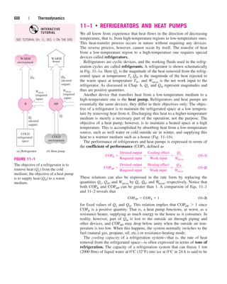
11–118 An absorption air-conditioning system is to remove
heat from the conditioned space at 20°C at a rate of 150 kJ/s
while operating in an environment at 35°C. Heat is to be sup-
plied from a geothermal source at 140°C. The minimum rate
of heat supply is
(a) 86 kJ/s (b) 21 kJ/s (c) 30 kJ/s
(d) 61 kJ/s (e) 150 kJ/s
11–119 Consider a refrigerator that operates on the vapor
compression refrigeration cycle with R-134a as the working
fluid. The refrigerant enters the compressor as saturated
vapor at 160 kPa, and exits at 800 kPa and 50°C, and leaves
the condenser as saturated liquid at 800 kPa. The coefficient
of performance of this refrigerator is
(a) 2.6 (b) 1.0 (c) 4.2
(d) 3.2 (e) 4.4
Design and Essay Problems
11–120 Design a vapor-compression refrigeration system
that will maintain the refrigerated space at 15°C while
operating in an environment at 20°C using refrigerant-134a
as the working fluid.
11–121 Write an essay on air-, water-, and soil-based heat
pumps. Discuss the advantages and the disadvantages of each
system. For each system identify the conditions under which
that system is preferable over the other two. In what situations
would you not recommend a heat pump heating system?
11–122 Consider a solar pond power plant operating on a
closed Rankine cycle. Using refrigerant-134a as the working
fluid, specify the operating temperatures and pressures in the
cycle, and estimate the required mass flow rate of refrigerant-
134a for a net power output of 50 kW. Also, estimate the sur-
face area of the pond for this level of continuous power
production. Assume that the solar energy is incident on the
pond at a rate of 500 W per m2 of pond area at noontime, and
that the pond is capable of storing 15 percent of the incident
solar energy in the storage zone.
11–123 Design a thermoelectric refrigerator that is capable
of cooling a canned drink in a car. The refrigerator is to be
powered by the cigarette lighter of the car. Draw a sketch of
your design. Semiconductor components for building thermo-
electric power generators or refrigerators are available from
several manufacturers. Using data from one of these manu-
facturers, determine how many of these components you need
in your design, and estimate the coefficient of performance of
your system. A critical problem in the design of thermoelec-
tric refrigerators is the effective rejection of waste heat. Dis-
cuss how you can enhance the rate of heat rejection without
using any devices with moving parts such as a fan.
648 | Thermodynamics
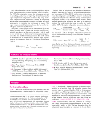
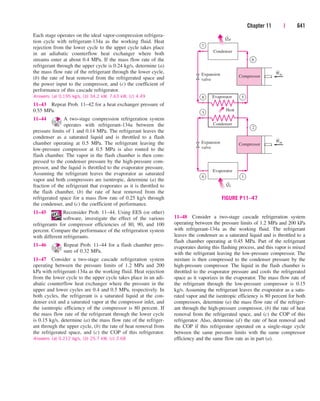
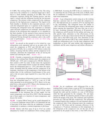
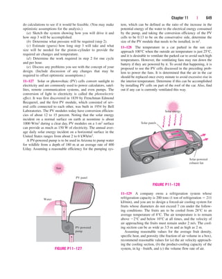
11–124 It is proposed to use a solar-powered thermoelectric
system installed on the roof to cool residential buildings. The
system consists of a thermoelectric refrigerator that is pow-
ered by a thermoelectric power generator whose top surface
is a solar collector. Discuss the feasibility and the cost of
such a system, and determine if the proposed system installed
on one side of the roof can meet a significant portion of the
cooling requirements of a typical house in your area.
Thermoelectric
refrigerator
Thermoelectric
generator
Electric
current
Solar
energy
Waste
heat
SUN
FIGURE P11–124
11–125 A refrigerator using R-12 as the working fluid
keeps the refrigerated space at 15°C in an environment at
30°C. You are asked to redesign this refrigerator by replacing
R-12 with the ozone-friendly R-134a. What changes in the
pressure levels would you suggest in the new system? How
do you think the COP of the new system will compare to the
COP of the old system?
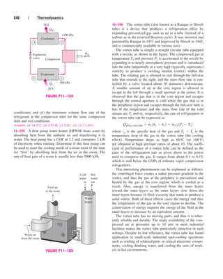
11–126 In the 1800s, before the development of modern
air-conditioning, it was proposed to cool air for buildings
with the following procedure using a large piston–cylinder
device [“John Gorrie: Pioneer of Cooling and Ice Making,”
ASHRAE Journal 33, no. 1 (Jan. 1991)]:
1. Pull in a charge of outdoor air.
2. Compress it to a high pressure.
3. Cool the charge of air using outdoor air.
4. Expand it back to atmospheric pressure.
5. Discharge the charge of air into the space to be
cooled.
Suppose the goal is to cool a room 6 m 10 m 2.5 m.
Outdoor air is at 30°C, and it has been determined that 10 air
changes per hour supplied to the room at 10°C could provide
adequate cooling. Do a preliminary design of the system and
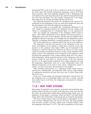
cen84959_ch11.qxd 4/4/05 4:48 PM Page 648](https://image.slidesharecdn.com/chapter11-220425210815/85/CHAPTER11-PDF-42-320.jpg)


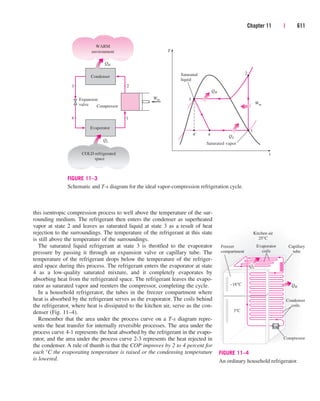
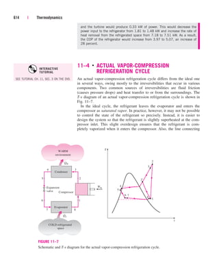
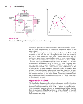
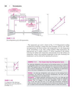
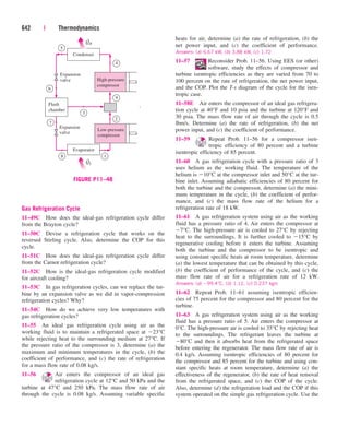
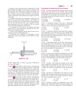
The document summarizes the ideal vapor-compression refrigeration cycle, which is the most widely used refrigeration cycle. It consists of four processes: (1) isentropic compression, (2) heat rejection in the condenser, (3) throttling, and (4) heat absorption in the evaporator. The refrigerant is compressed from a saturated vapor to a superheated vapor, rejects heat as a saturated liquid, throttles to a low-quality mixture, and fully evaporates by absorbing heat. This cycle is not internally reversible due to the throttling process but provides a realistic model for actual vapor-compression refrigeration systems.


