Cont…..
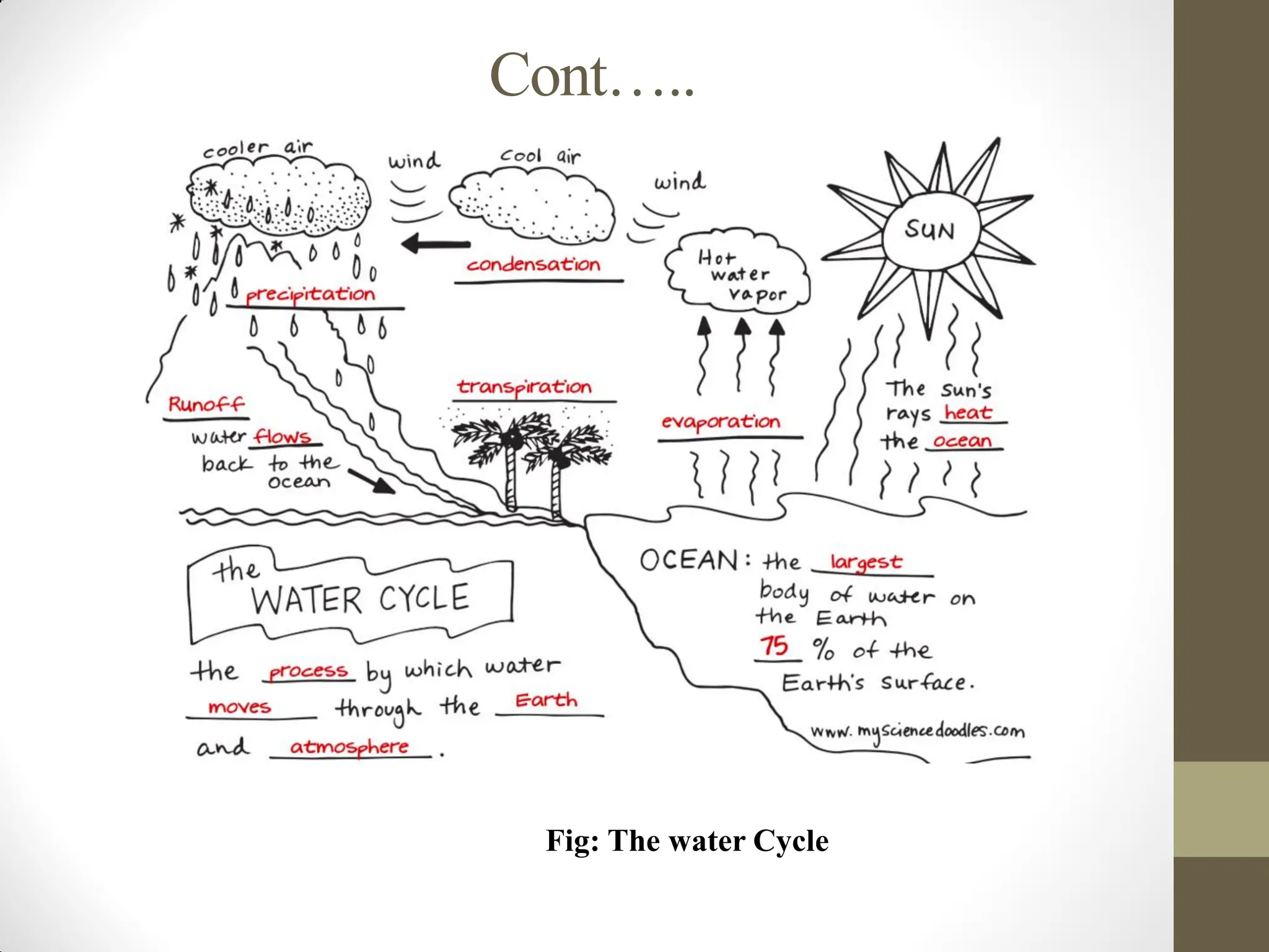
• THE WATERCYCLES
The origin of all water is rainfall.
Water can be collected:
as it falls as rain before it reaches the ground;
as surface water when it flows over the
ground; or is pooled in lakes or ponds;
as ground water when it percolates in to the
ground and flows or collects as ground water;
from the sea (ocean) in to which it finally
flows.
Cont…..
• Types ofwater sources
sources of water can be broadly divided into:
1. Surfaces sources and
2. Sub surface sources
1. surface sources
The surface sources further divided into:
i. Streams and rivers
ii. Ponds and Lakes
iii.Impounding reservoirs etc.
I. Streams and Rivers
A stream or river is a body of running water on the surface of
the earth, from higher to lower ground.
Rivers are the surface sources of water from which maximum quantity
of water can be easily taken.
5.
Cont…..
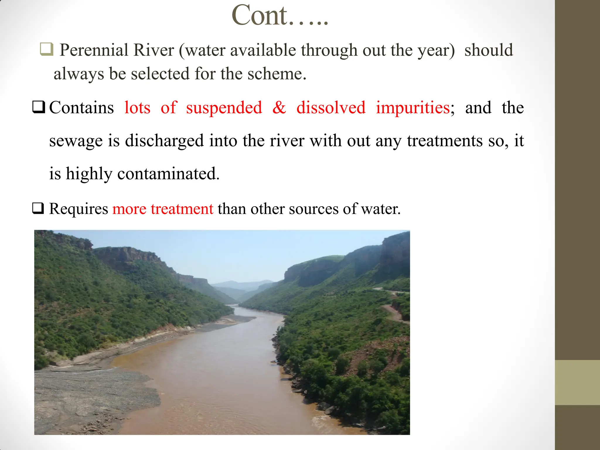
Perennial River(water available through out the year) should
always be selected for the scheme.
Contains lots of suspended & dissolved impurities; and the
sewage is discharged into the river with out any treatments so, it
is highly contaminated.
Requires more treatment than other sources of water.
6.
Cont…..
2. Ponds andLakes
A lake is a natural depression/hollow filled with water,
while a pond is an artificial depression filled with water,
often created by digging the ground.
The quantity of water in the lakes depends on its basin
capacity, catchments area, annual rainfall, porosity of the
ground, etc.
It is a standing water and hence the quality is very low:
(turbidity, bacteria and pollutants, thermal stratification
for deep lakes)
7.
Cont…..
ponds formeddue to construction of houses, road, and
railways contains large amount of impurities and therefore
cannot be used for water supply purposes.
The pond water can be used only for bathing, washing of
clothes or for animals.
3. Impounding Reservoirs
In some rivers the flow becomes very small and cannot meet
the requirements of hot weather.
In such cases, the water can be stored by constructing weir or a
dam across the river at such places where minimum area of
land is submerged in the water and maximum quantity of water
to be stored.
8.
Cont…..
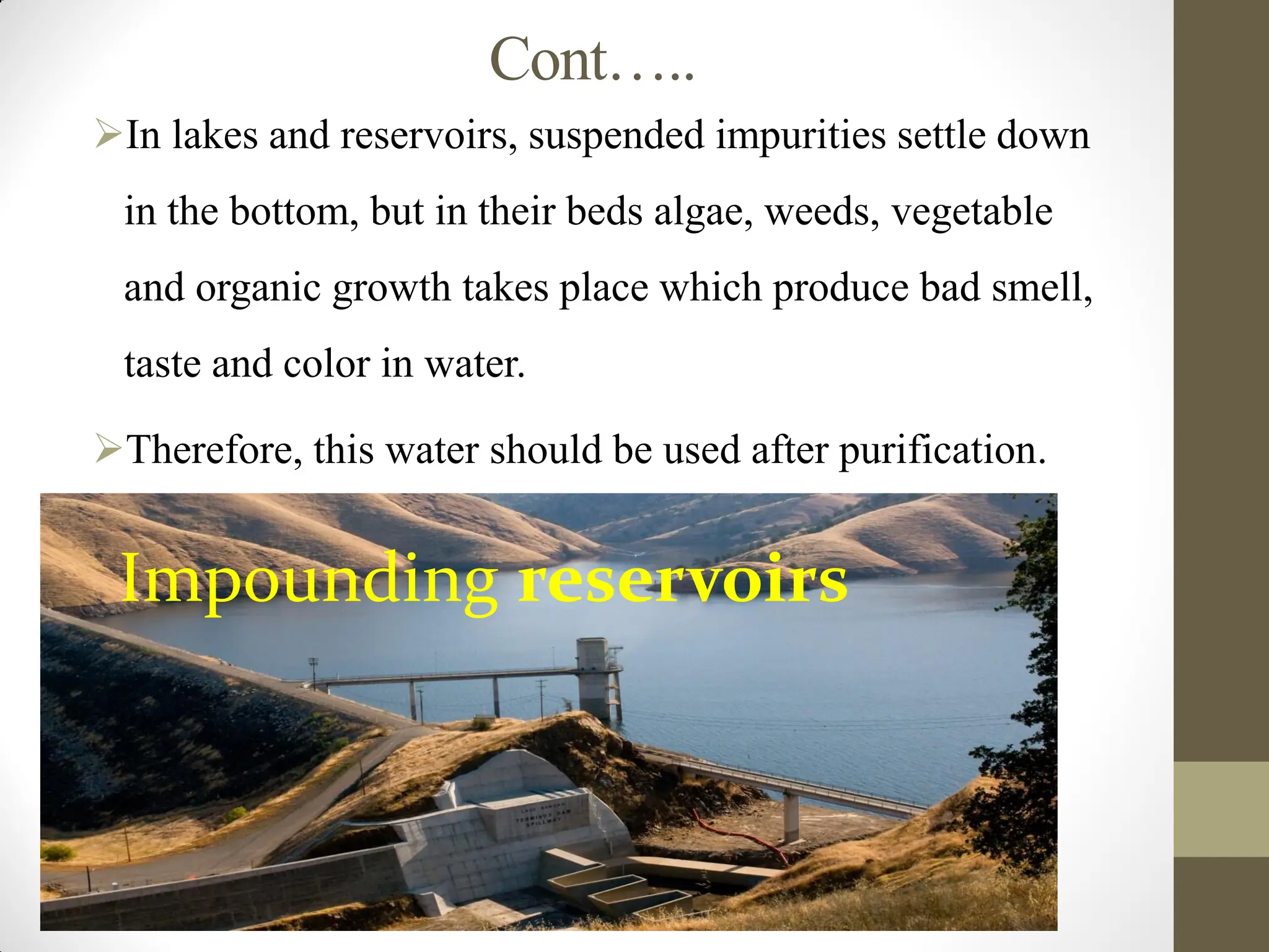
In lakes andreservoirs, suspended impurities settle down
in the bottom, but in their beds algae, weeds, vegetable
and organic growth takes place which produce bad smell,
taste and color in water.
Therefore, this water should be used after purification.
Impounding reservoirs
9.
Cont…..
2. SUB-SURFACE SOURCES
•These are further divided into
I. Springs
II. Infiltration galleries
III.Infiltration wells
IV.Well
1. Spring
Sometimes ground water reappears at the ground surface
in the form of springs.
Springs generally supply small quantity of water and
hence suitable for the hill towns.
Cont…..
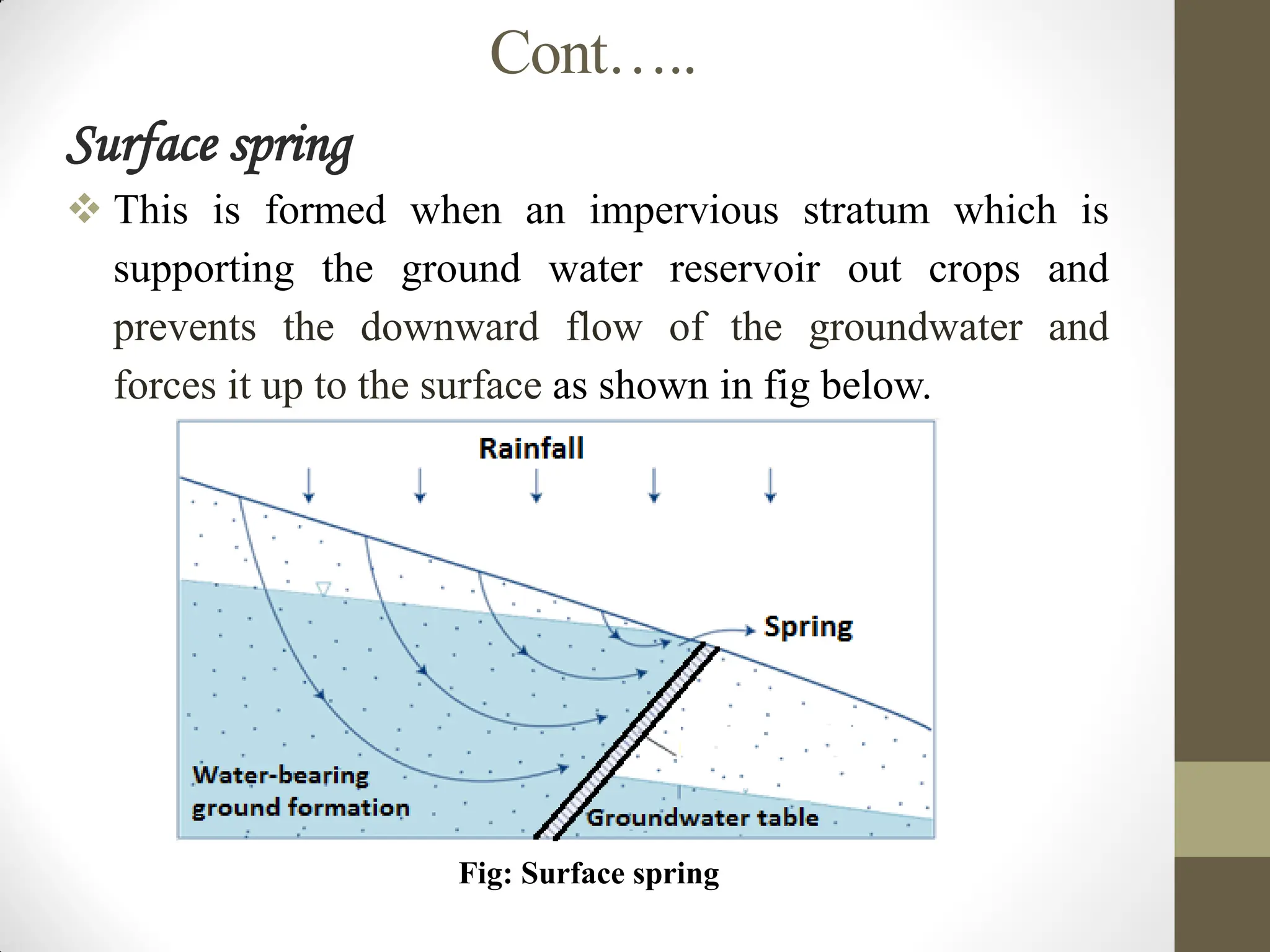
Surface spring
Thisis formed when an impervious stratum which is
supporting the ground water reservoir out crops and
prevents the downward flow of the groundwater and
forces it up to the surface as shown in fig below.
Fig: Surface spring
12.
Cont….
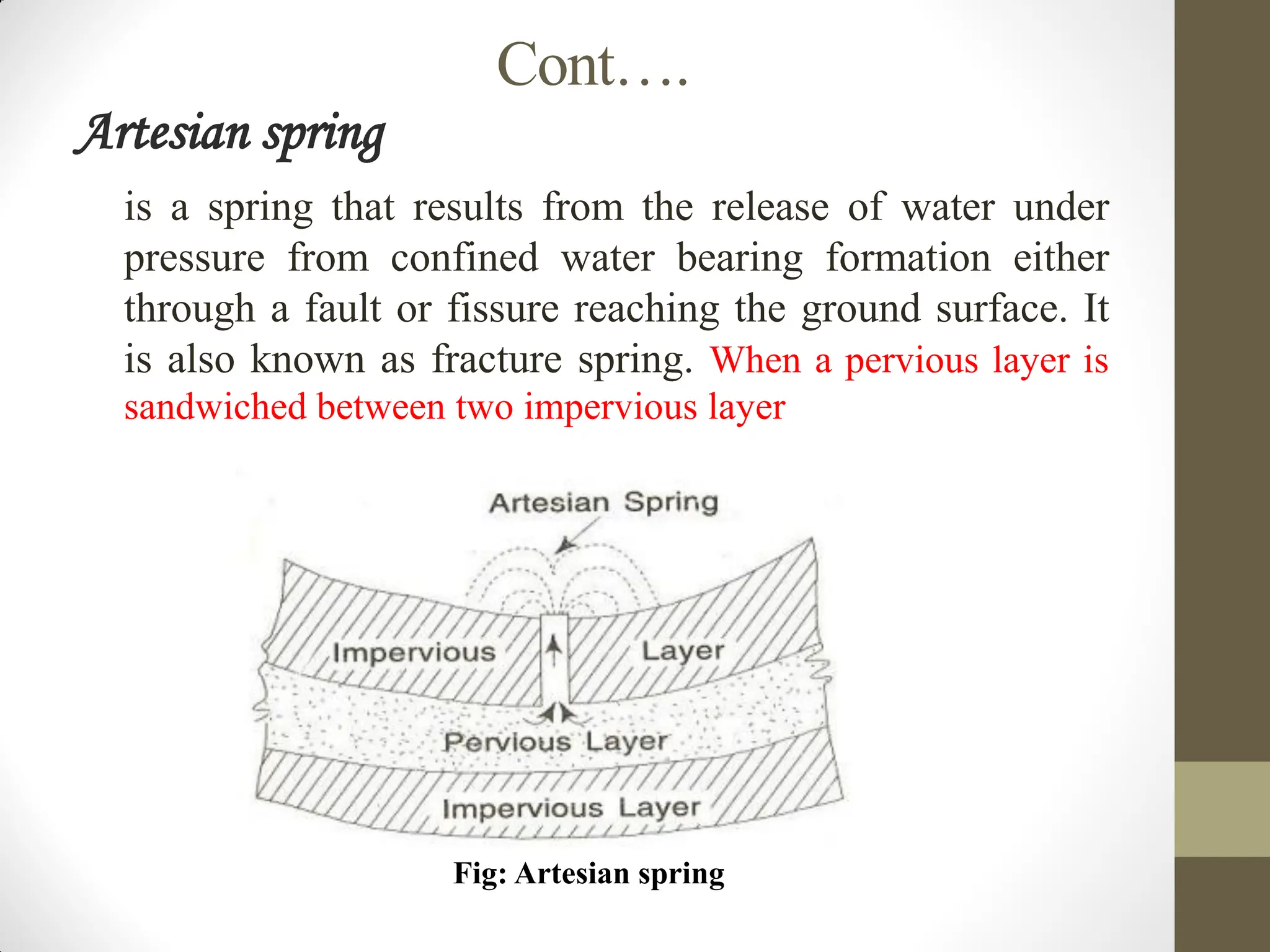
Artesian spring
isa spring that results from the release of water under
pressure from confined water bearing formation either
through a fault or fissure reaching the ground surface. It
is also known as fracture spring. When a pervious layer is
sandwiched between two impervious layer
Fig: Artesian spring
13.
Cont…..
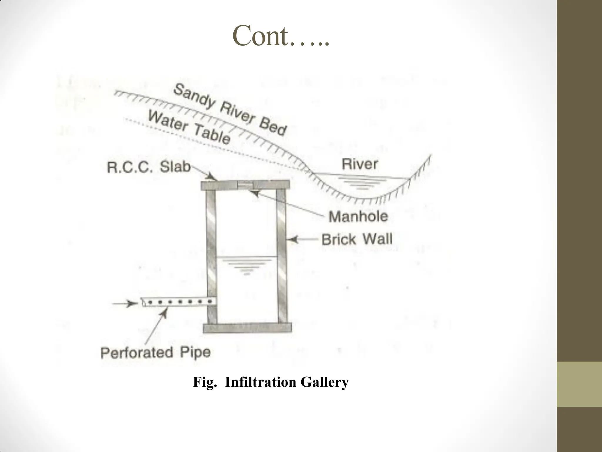
2. Infiltration Gallery:
Ahorizontal or nearly horizontal tunnel which is constructed
through water bearing strata for tapping underground water
near rivers, lakes or streams are called “Infiltration galleries”.
It is sometimes referred as horizontal well.
For maximum yield the galleries may be placed at full depth
of the aquifer.
Infiltration galleries may be constructed with masonry or
concrete with weep holes of 5cm x 10cm.
Cont…..
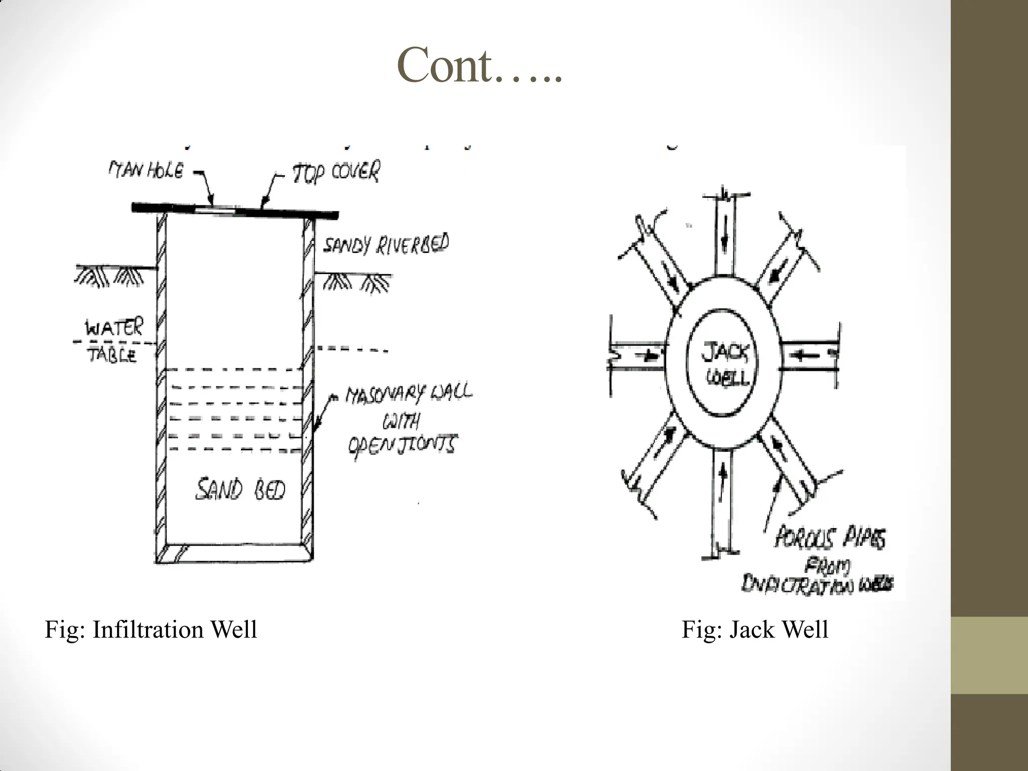
3. Infiltration wells
Theseare shallow wells constructed under the sandy river bed.
The wells are closed at top and open at bottom. They are
constructed by brick masonry with open joints as shown in fig.
below.
For the purpose of inspection of well, the manholes are
provided in the top cover.
The water filtrates through the bottom of such wells and as it
has to pass through sand bed, it gets purified to some extent.
The infiltration wells in turn are connected by porous pipes to
collecting sump called jack well and there water is pumped to
purification plant for treatment.
Cont…..
4. wells
• Awell is defined as artificial holes or pits vertically excavated for
bringing ground water to the surface.
• The three factors which form the basis of theory of wells are
1. Geological conditions of the earth’s surface.
2. Porosity of various layers.
3. Quantity of water, which is absorbed and stored in different
layers.
• The following are different types of wells
I. Open well
II. Tube wells
18.
Cont…..
Open well
• Itis constructed by digging the earth.
- It draws water from the topmost pervious layer.
- The diameter of this well varies from 1m to 2m and the depth
varies from 20m to 30m depending upon the nature of soil
& the water table.
Tube well:
• It is constructed by sinking G.I pipes.
- It draws water from the deeper most pervious layer.
- The diameter and the depth of this well varying from
37mm to 150 mm and 100m to 200m respectively,
depending upon the nature of soil and suitable water
bearing strata.
19.
Cont……
Alternatives water sources
a)Desalination: it makes saline or brackish water
drinkable.
Methods include distillation, reverse osmosis,
electrodialysis, freezing, and solar evaporation
b) Reuse of treated wastewater (WW): Treated
WW can be reused for non-potable purposes such as
irrigation, industrial processes, artificial groundwater
aquifer recharge, and toilet flushing after suitable
treatment.
20.
Cont…..
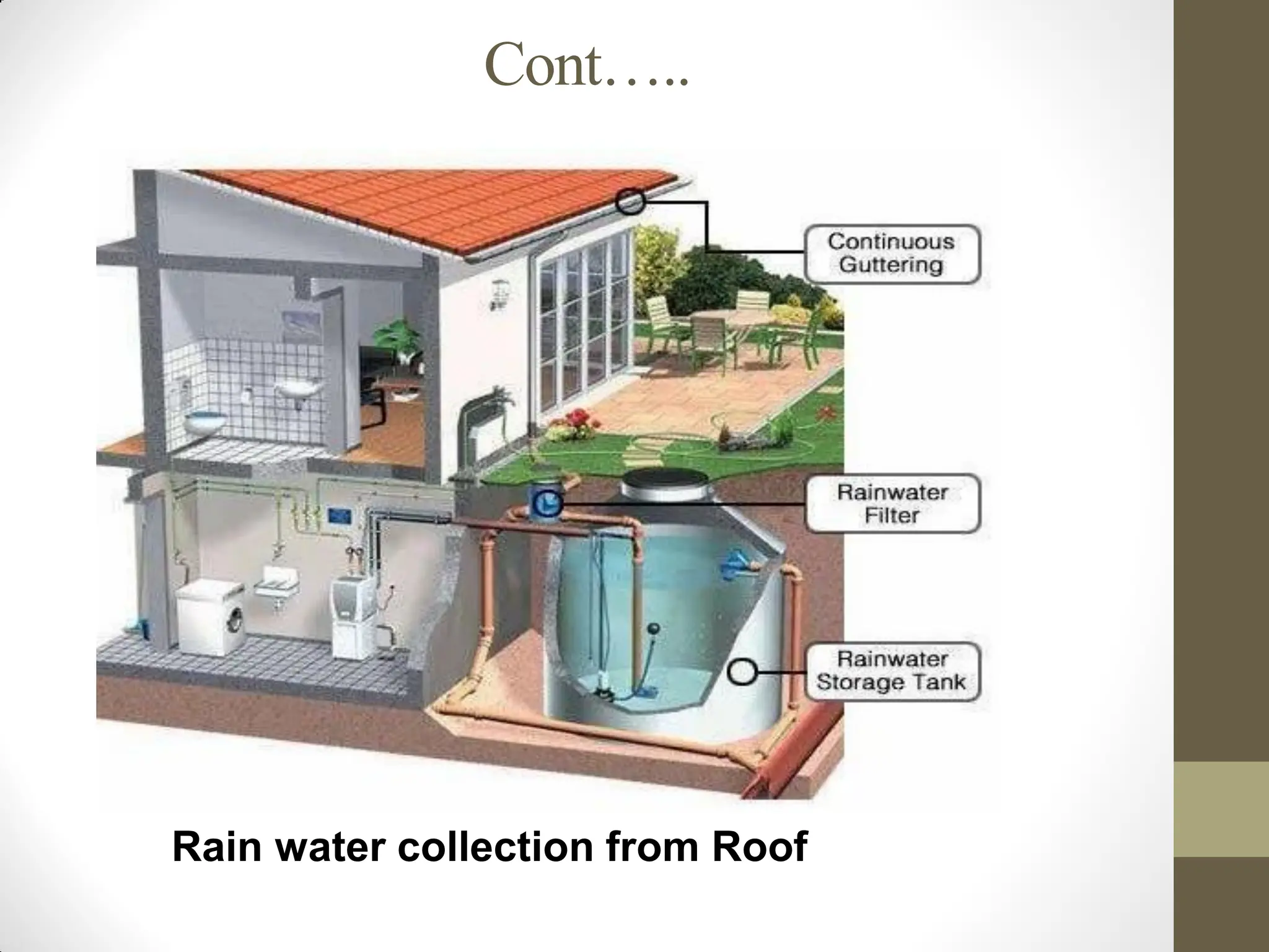
c) Rain waterharvesting:
Rain is the principal source of all water sources.
Rain water might contain dust, smoke, bacteria, carbon dioxide… as
falling from high altitude
Roofs are effective catchments for rainwater harvesting and can
be integrated with tanks.
Rainwater quality is better on open land than in urban
areas/cities.
Rain water is soft water but flat to the taste and corrosive in
nature.
Rainwater is not typically used as an immediate source of
municipal water.
Cont…..
WATER SOURCES SELECTIONCRITERIA
Location: The sources of water should be as near as to
the town as possible.
Quantity of water: the source of water should have
sufficient quantity of water to meet up all the water
demand through out the design period.
Quality of water: The quality of water should be good
which can be easily and cheaply treated.
Cost: The cost of the units of the water supply schemes
should be minimum.
Topography: The land between the water source and
the city should not have steep valleys or tall
mountains.
Elevation of the source: The water source should be
at a higher elevation than the city so that water can
flow to the city by gravity.
23.
Cont…..
SURFACE WATER INTAKES
An intake is a device/structure placed in a surface-water
source to withdraw water.
It discharges water into an intake conduit leading to the
treatment plant.
The structure can be made of stone masonry, brick
masonry, R.C.C., or concrete blocks.
It must be watertight and designed to withstand water
pressure, wave action, wind, and floating debris
24.
Cont…..
Location for Intakesstructures
The intake should not be placed downstream or near
where the city disposes of sewage or wastewater, or
in a location with pollution hazards.
The intake should be located at a place where it can
draw water even during the driest periods of the year.
It should be as near to treatment plant as possible
The intake structure site should allow for future
expansions to increase water withdrawal if needed.
25.
Cont…..
Magnitude anddirection of stream or current velocities
should not affect the function and stability of the intake
structure.
Reliable access roads and power sources should be
available should be near to treatment plant.
Major environmental impacts should be avoided.
The intake should not be near the navigation channel to
avoid pollution from ship and boat waste.
26.
Cont…..
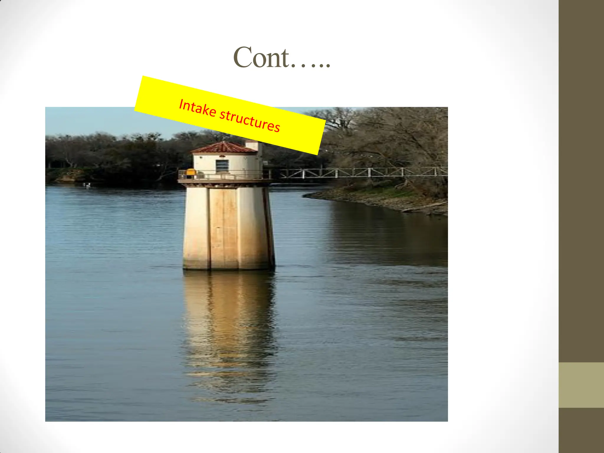
Types of Intakestructures
The common types of intakes used for surface-water
sources are:
1-River intake
2-Canal intake
3-Reservoir intake
4-Lake intake (Simple submerged intake)
27.
Cont…..
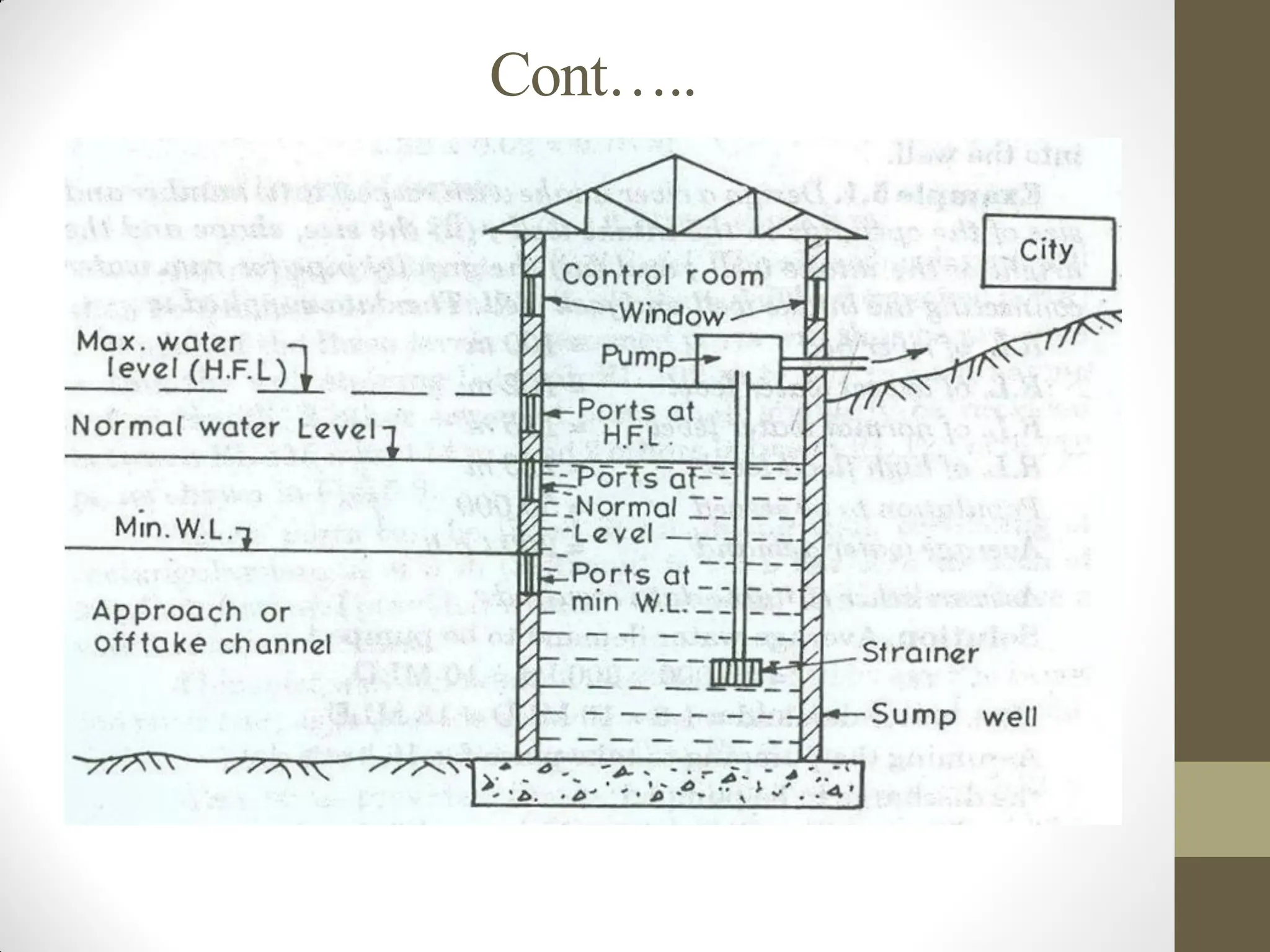
1. River Intake:
Always located on the upstream side of the town because
it is free from the contamination.
It is located on the river at a place where water can be
withdrawn in sufficient quantity even during the
minimum water level.
It is circular masonry tower of 4 to 7 m in diameter
constructed along the bank of the river.
Cont…..
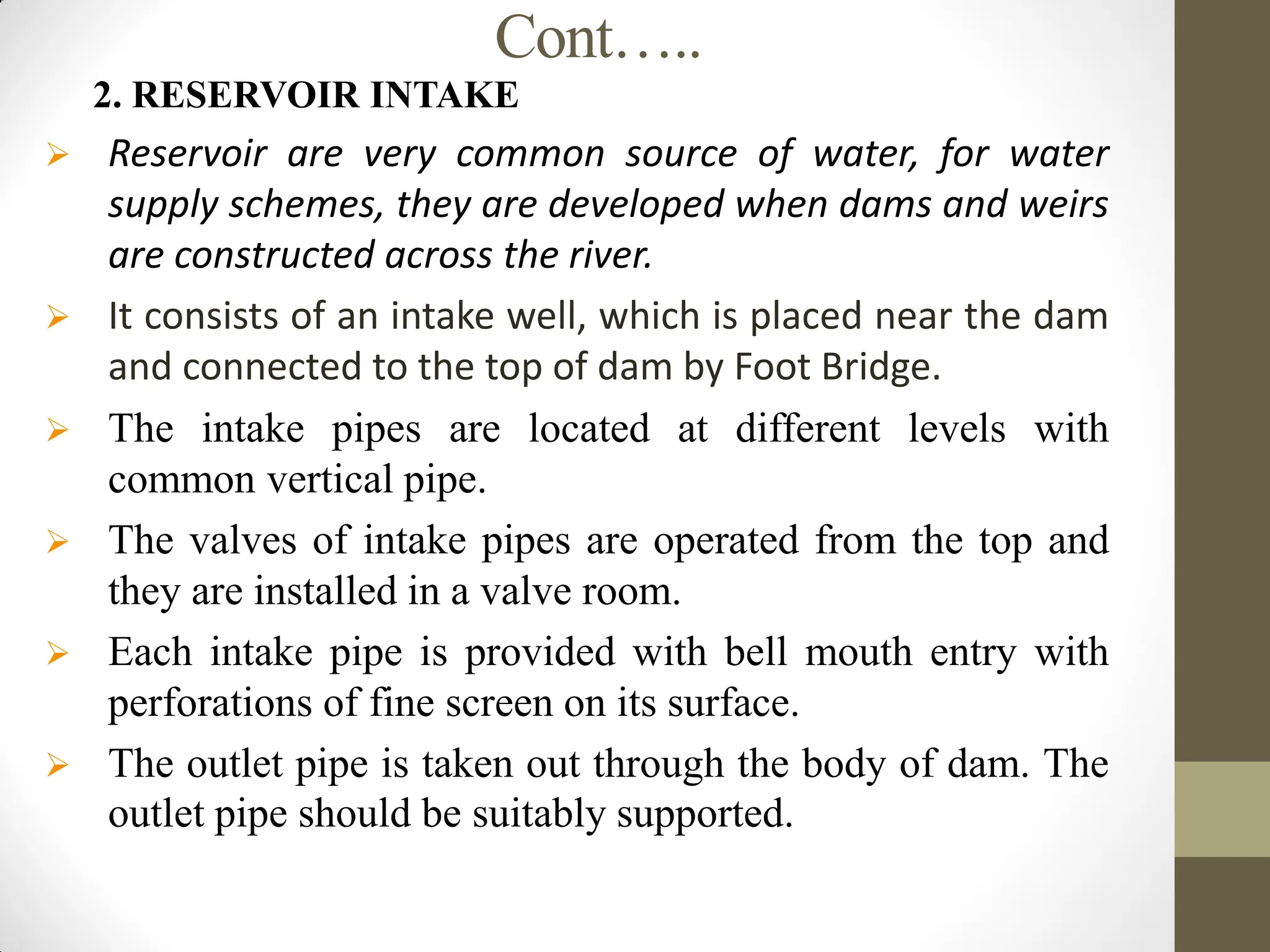
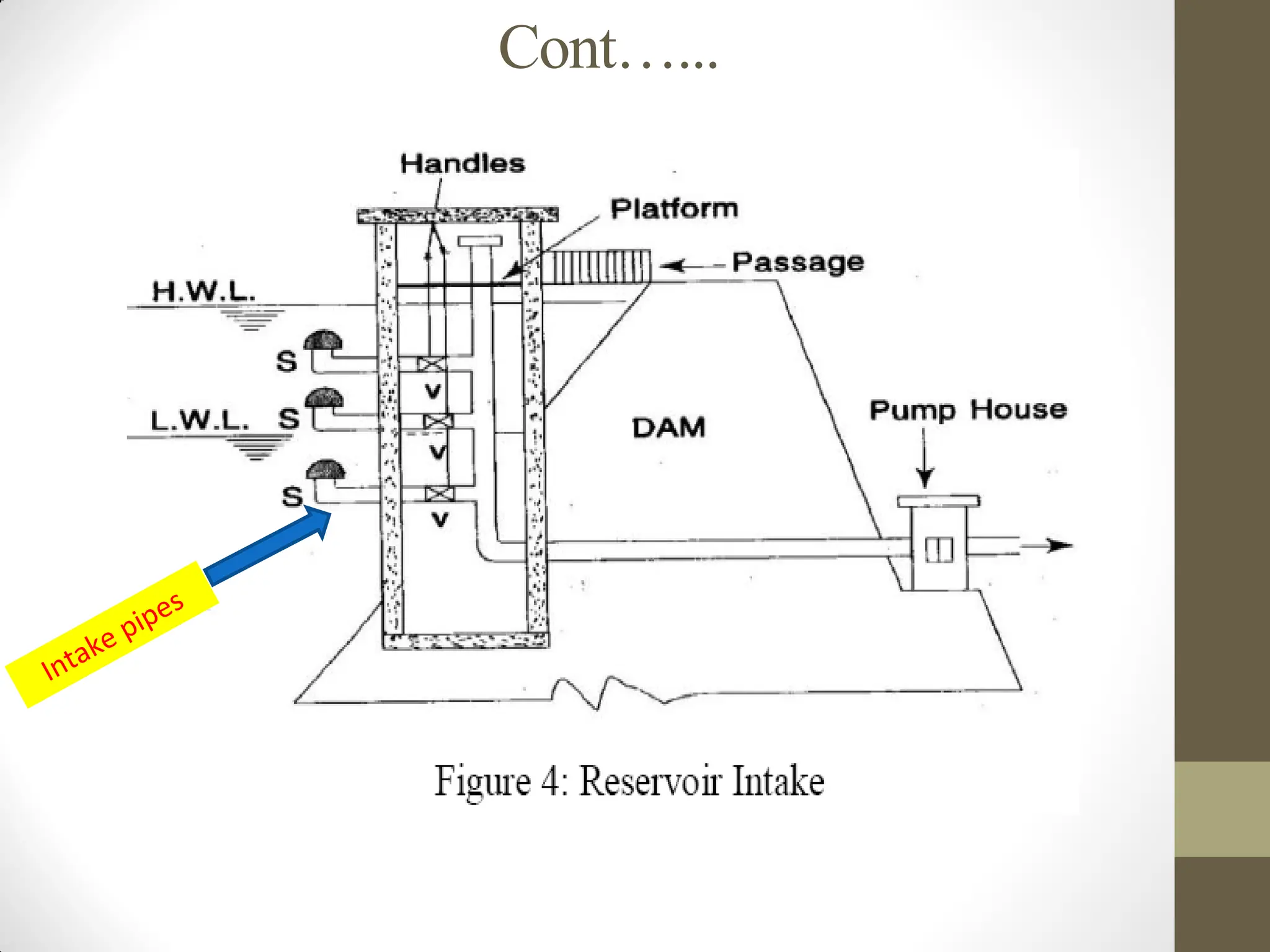
2. RESERVOIR INTAKE
Reservoir are very common source of water, for water
supply schemes, they are developed when dams and weirs
are constructed across the river.
It consists of an intake well, which is placed near the dam
and connected to the top of dam by Foot Bridge.
The intake pipes are located at different levels with
common vertical pipe.
The valves of intake pipes are operated from the top and
they are installed in a valve room.
Each intake pipe is provided with bell mouth entry with
perforations of fine screen on its surface.
The outlet pipe is taken out through the body of dam. The
outlet pipe should be suitably supported.
Cont…..
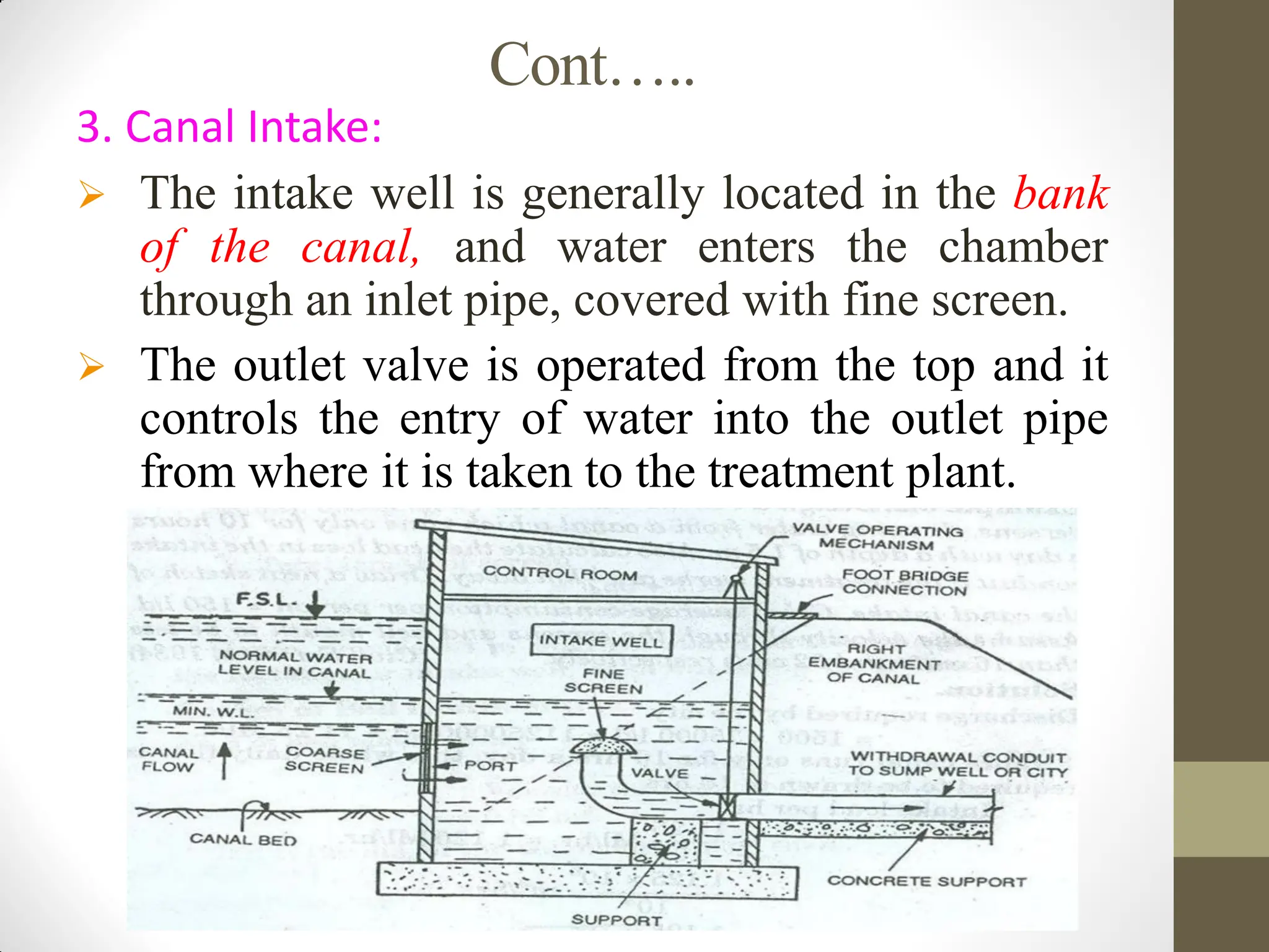
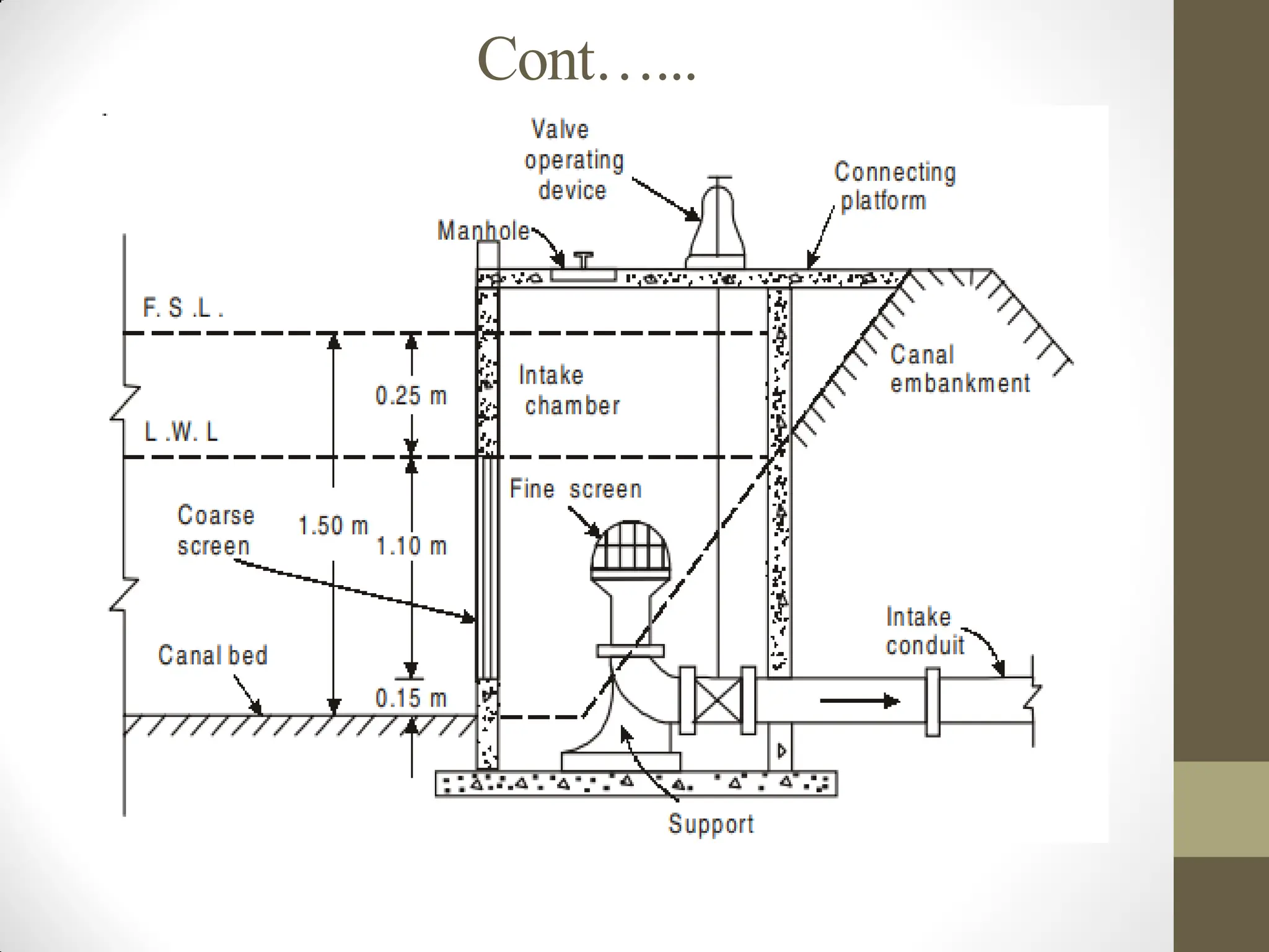
3. Canal Intake:
The intake well is generally located in the bank
of the canal, and water enters the chamber
through an inlet pipe, covered with fine screen.
The outlet valve is operated from the top and it
controls the entry of water into the outlet pipe
from where it is taken to the treatment plant.
33.
Cont…..
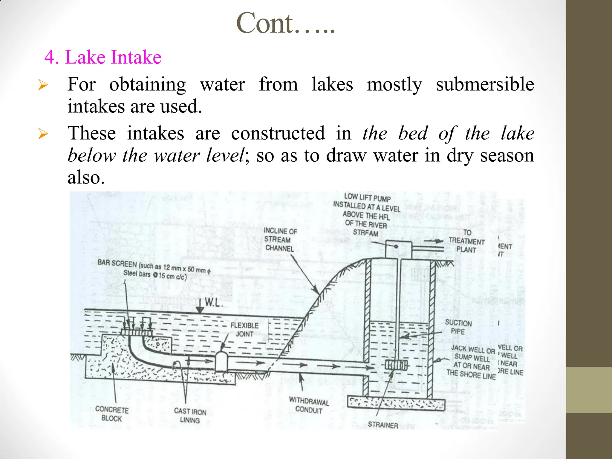
4. Lake Intake
For obtaining water from lakes mostly submersible
intakes are used.
These intakes are constructed in the bed of the lake
below the water level; so as to draw water in dry season
also.
34.
Cont…...
Design Consideration forIntake Structures:
Intake should be sufficiently heavy, so that, it may not float
due to up thrust of water.
All the forces which are expected to work on the intake should
be carefully analyzed and intake should be designed to with
stand all of them.
The foundation of the intake should be taken sufficiently deep.
This will avoid undermining and over turning of the structure.
Strainers in the form of wire mesh should be provided on all
the intake inlet.
Inlets should be such size and so located that sufficient
quantity of water can be availed from the intake in all the
circumstances.
35.
Cont…..
Design Criteria forintake structures
Design capacity = Q max-day
• Intake velocity should be <8 cm/s. Too low velocities
that require large intake ports should also be avoided.
• Vertical positions intake ports should be such that good
quality water is withdrawn.
• Locate the top intake port at a distance not less than 2 m
from the normal water level and the bottom port at least
1 m above the bottom.
36.
Cont…..
Intake design
Properdesign of the intake structure is one way of achieving
preliminary treatment.
An intake generally consists of a conduit with some protective screens
at open end and gates or valves for regulating the flow.
Bar Screens are provided to screen out larger size floating and
suspended materials. Sometimes two filters are provided successively
for coarse and fine screening.
Inlet pipe: Location below LWL in the stream should be ≈ 1m but
above stream bed ≈ from 0.3 to 0.5 m.
Sump=inlet well, height with FB of 0.5m
Volume of sump -detention time. A Td of at least 20min is
recommended.
At least two sumps -to avoid interruption of service.
Location of the bottom of the sump should be > 1.5m below the
lowest stream level or > 1m below stream bed.
37.
Cont…..
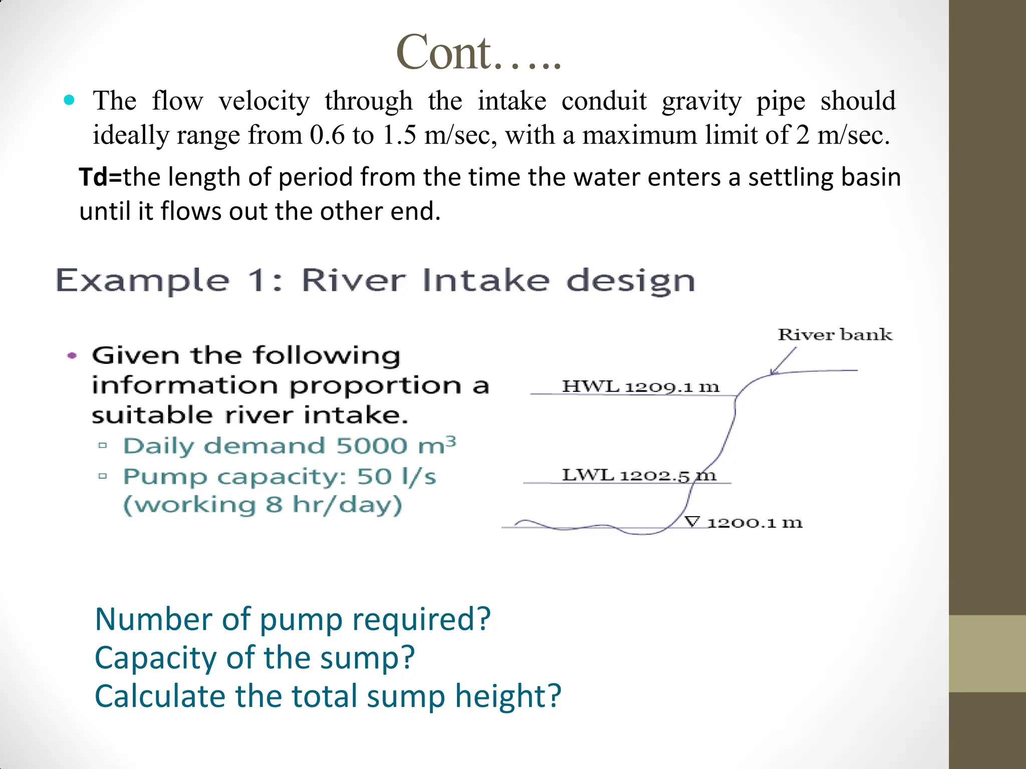
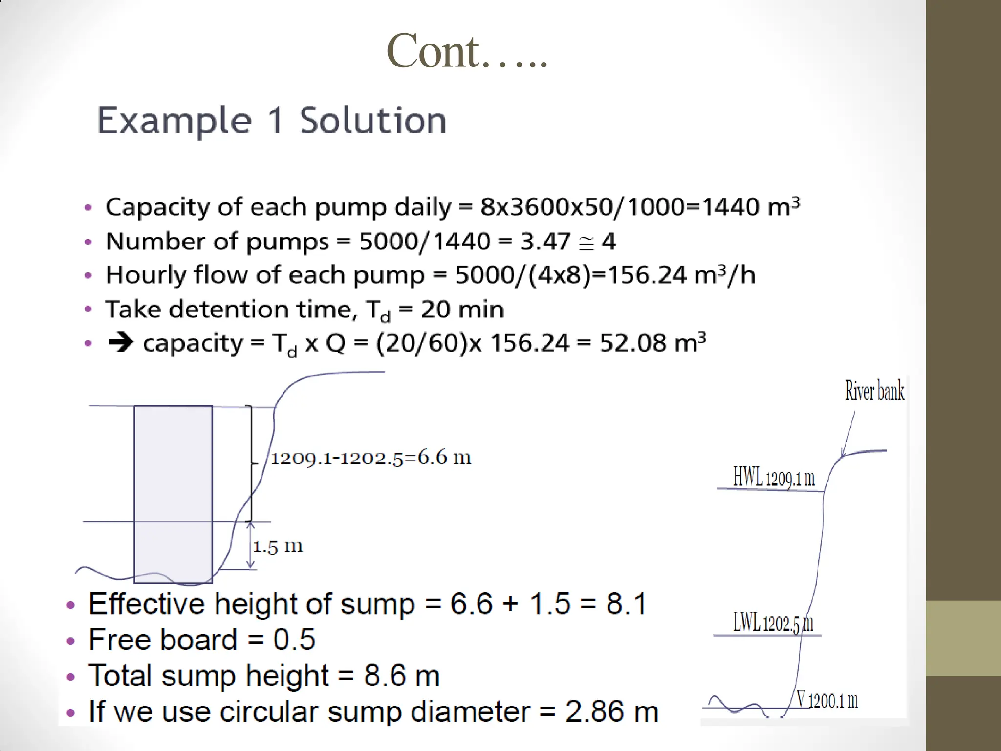
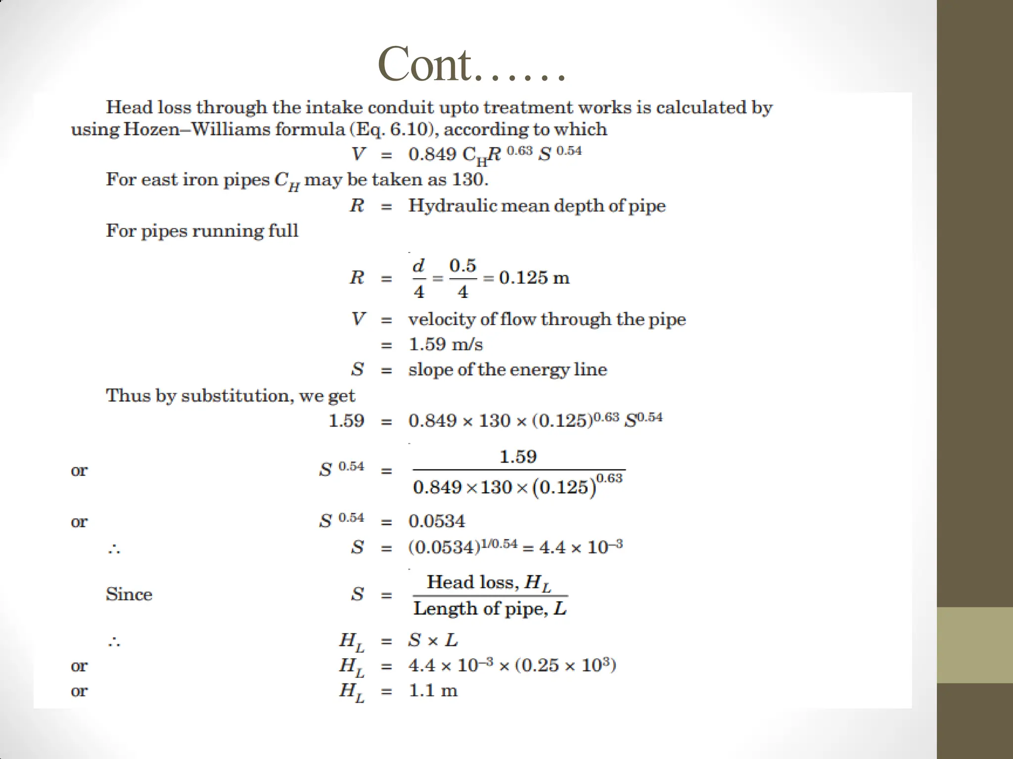
The flowvelocity through the intake conduit gravity pipe should
ideally range from 0.6 to 1.5 m/sec, with a maximum limit of 2 m/sec.
Td=the length of period from the time the water enters a settling basin
until it flows out the other end.
Number of pump required?
Capacity of the sump?
Calculate the total sump height?
Cont…..
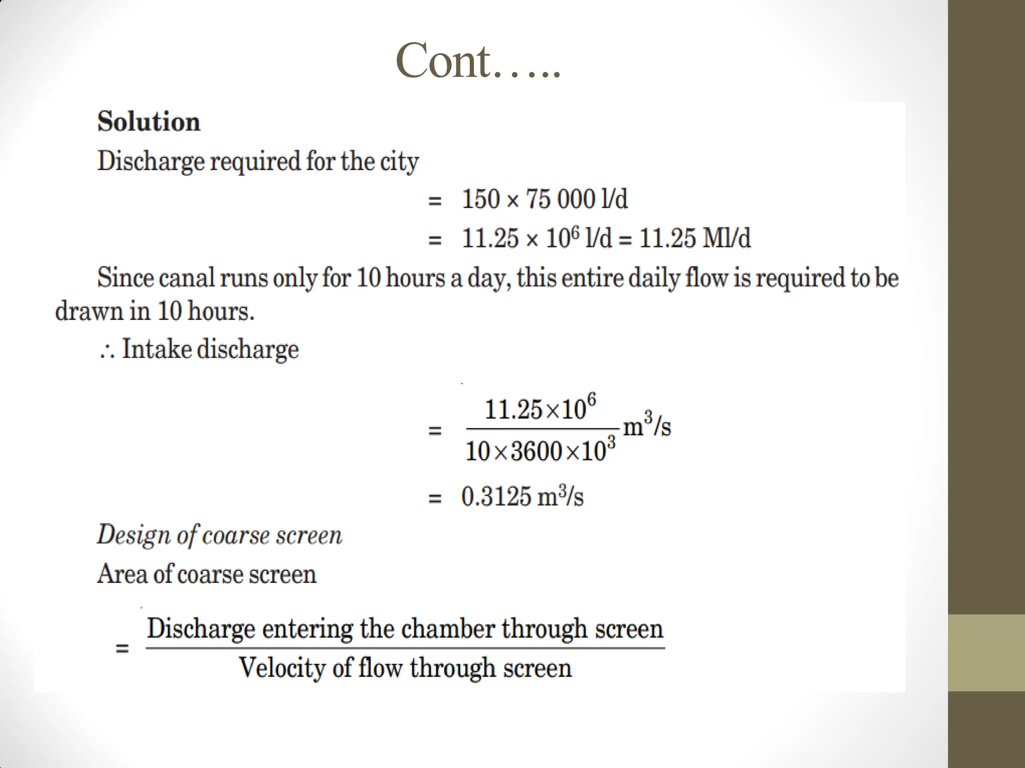
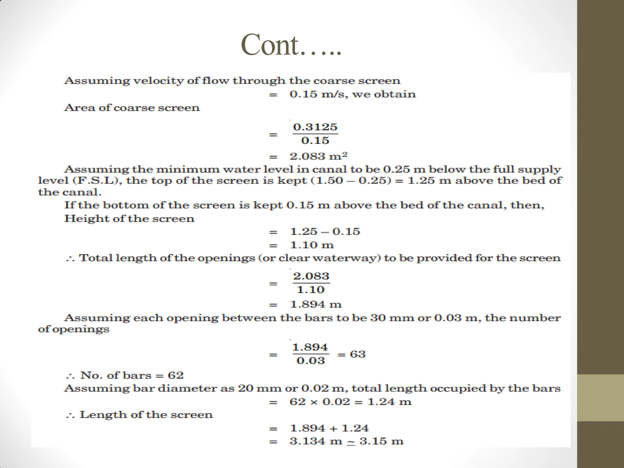
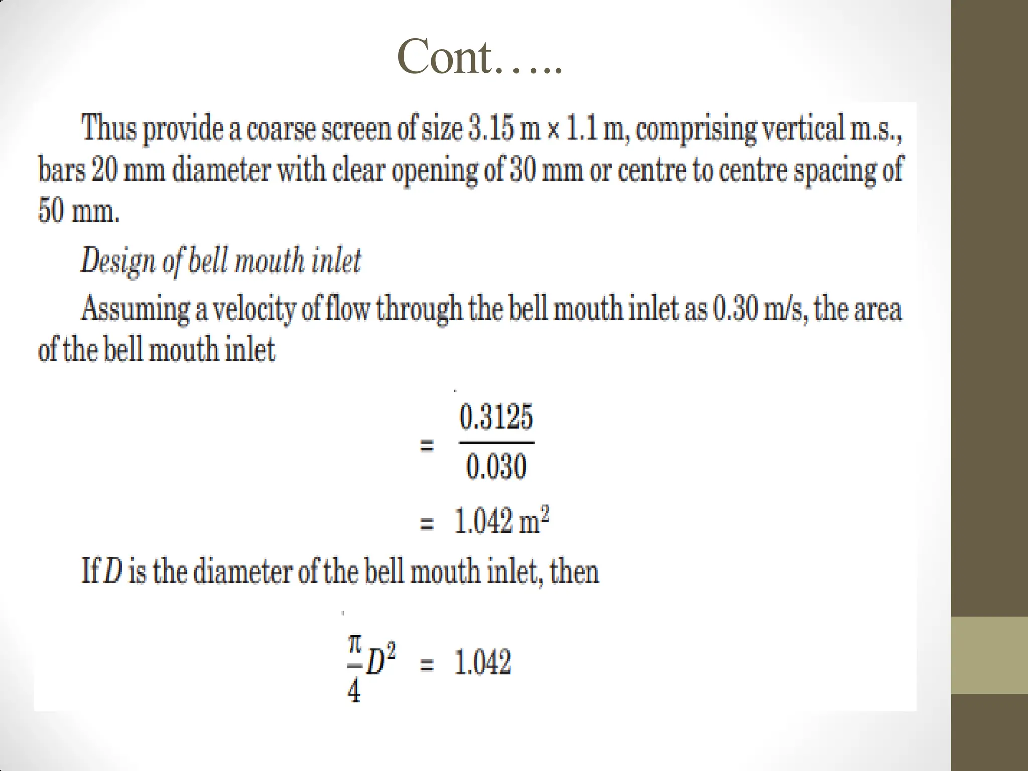
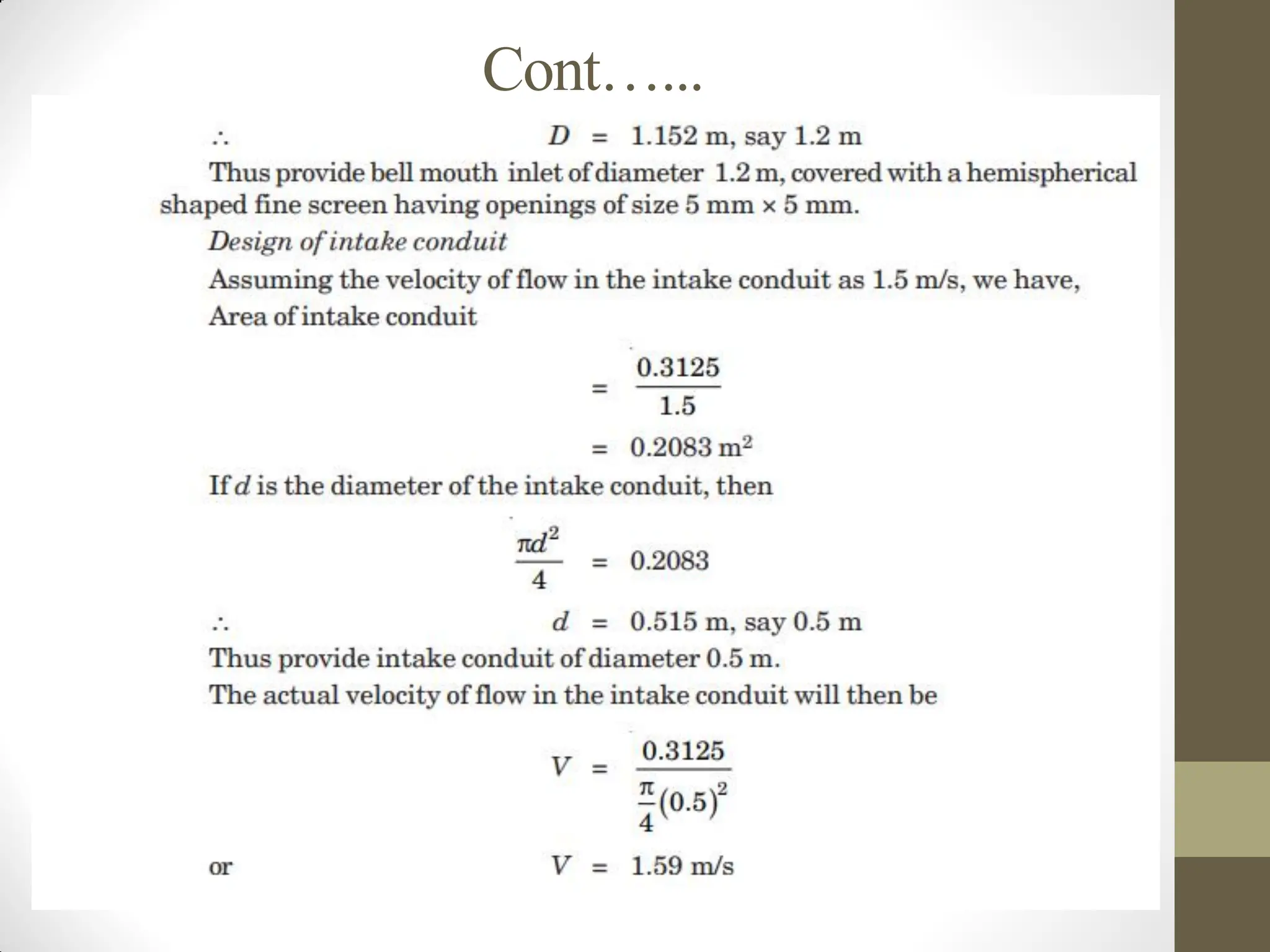
• Example 2.Design a bell mouth canal intake for a city of
population 75000, drawing water from a canal which runs
only for 10 hours a day with a flow depth of 1.5 m. Also
calculate the head loss in the intake conduit if the
treatment works are 0.25 km away. Draw a neat sketch of
the canal intake. Given the average consumption per
person = 150 litters/day. The velocity of flow through the
screen and bell mouth to be less than 0.16 m/s and 0.32
m/s respectively.
Cont…..
GROUND WATER FLOWHYDRAULICS
What is groundwater?
Groundwater is subsurface water which occurs beneath the
earth’s surface.
It comes from surface waters (precipitation, lake,
reservoir, river, sea, etc.) and percolates into the
ground beneath the water table.
The groundwater table is the surface of the groundwater
exposed to an atmospheric pressure beneath the ground surface
(the surface of the saturated zone).
47.
Cont……
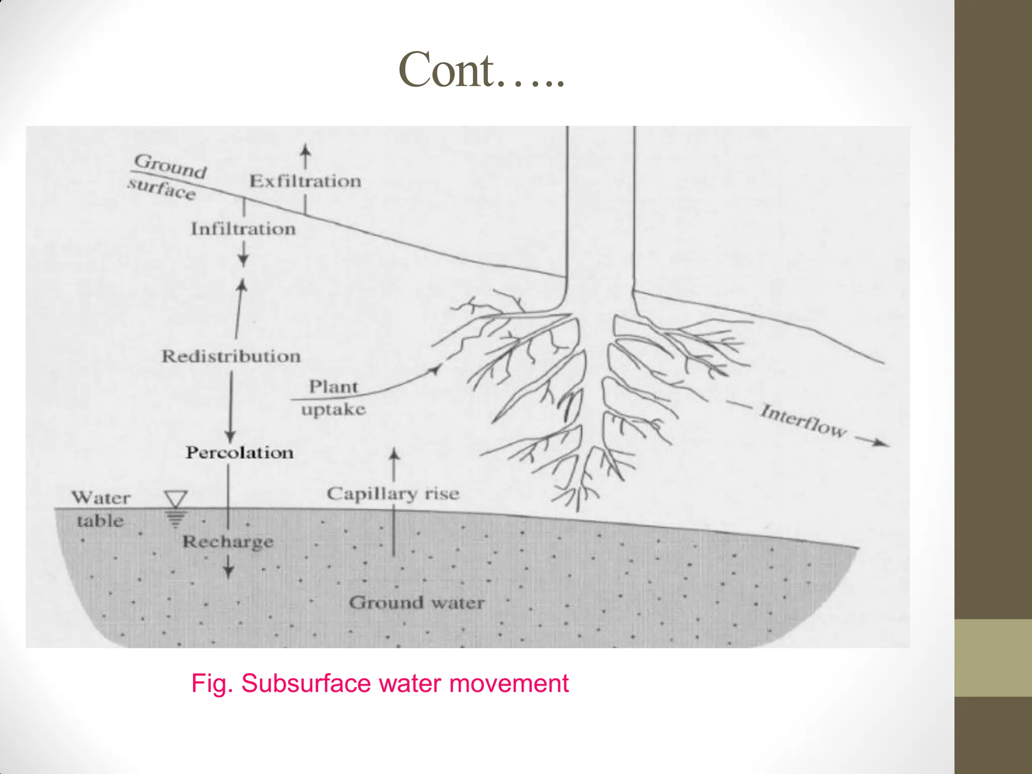
• Basic termsin ground water flow
The first entering of the water into the soil is called infiltration.
Downward transport of water in the unsaturated zone is called
percolation.
The upward transport of the water to the unsaturated zone is called
capillary rise.
oThe flow of water through saturated porous media is called
groundwater flow.
The lateral or horizontal flow of water from ground to surface is
called seepage.
Precipitation: Rain, snow, etc that falls.
Evaporation: the process of changing the liquid into vapour.
Transpiration: is the process of water passing out from the surface
of plant leaf.
Condensation: vapor changing into liquid.
48.
Cont……
Occurrence of Groundwater
After rain fall reach into the ground part of the rain falling
over the land surface infiltrates into the soil and the remaining
flows down as surface runoff.
Most of the water that infiltrates into the soil travels
down to recharge the vast groundwater stored at a
depth within the earth.
In fact, the groundwater reserve is actually a huge source of
fresh water and is many times that of surface water.
Cont…..
Two zones canbe distinguished in which water occurs in
the ground:
A) Unsaturated zone/ zone of aeration
B) Saturated zone
A) Unsaturated Zone: This is also known as zone of
aeration. In this zone the soil pores are only partially
saturated with water.
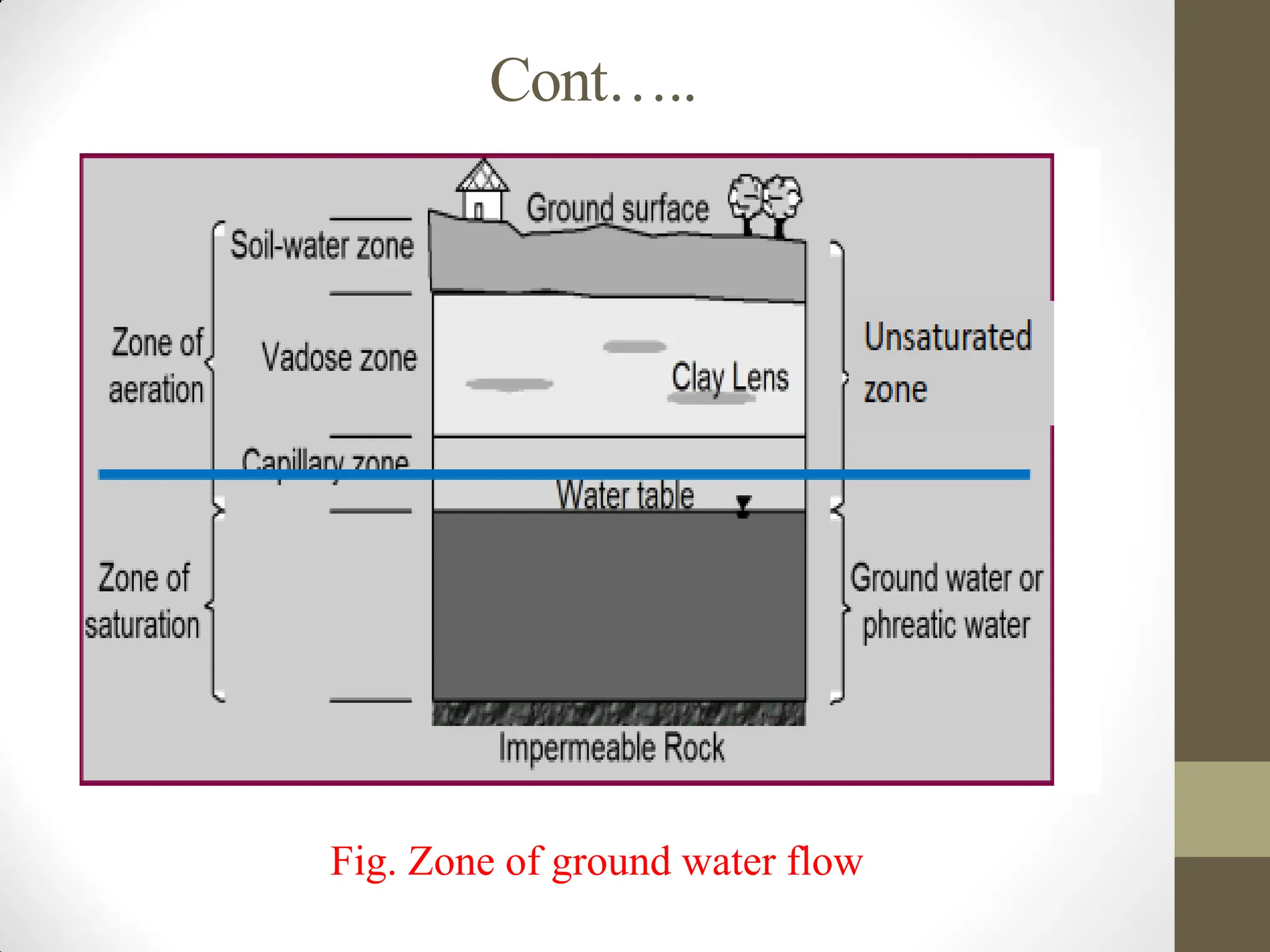
The zone of aeration has three sub zones:
a) Soil water zone
b) Capillary fringe and
c) Intermediate zone
51.
Cont……
The soilwater zone lies close to the ground surface in the
major root band of the vegetation from which the water is
lost to the atmosphere by evapotranspiration.
Capillary fringe hold water by capillary action. This zone
extends from the water table upwards to the limit of the
capillary rise.
The intermediate zone lies between the soil water zone
and the capillary fringe.
• The thickness of the zone of aeration and its constituent
sub-zones depend upon
- the soil texture,
- moisture content and vary from region to region.
• The soil moisture in the zone of aeration is of importance
in agricultural practice and irrigation engineering.
Cont……
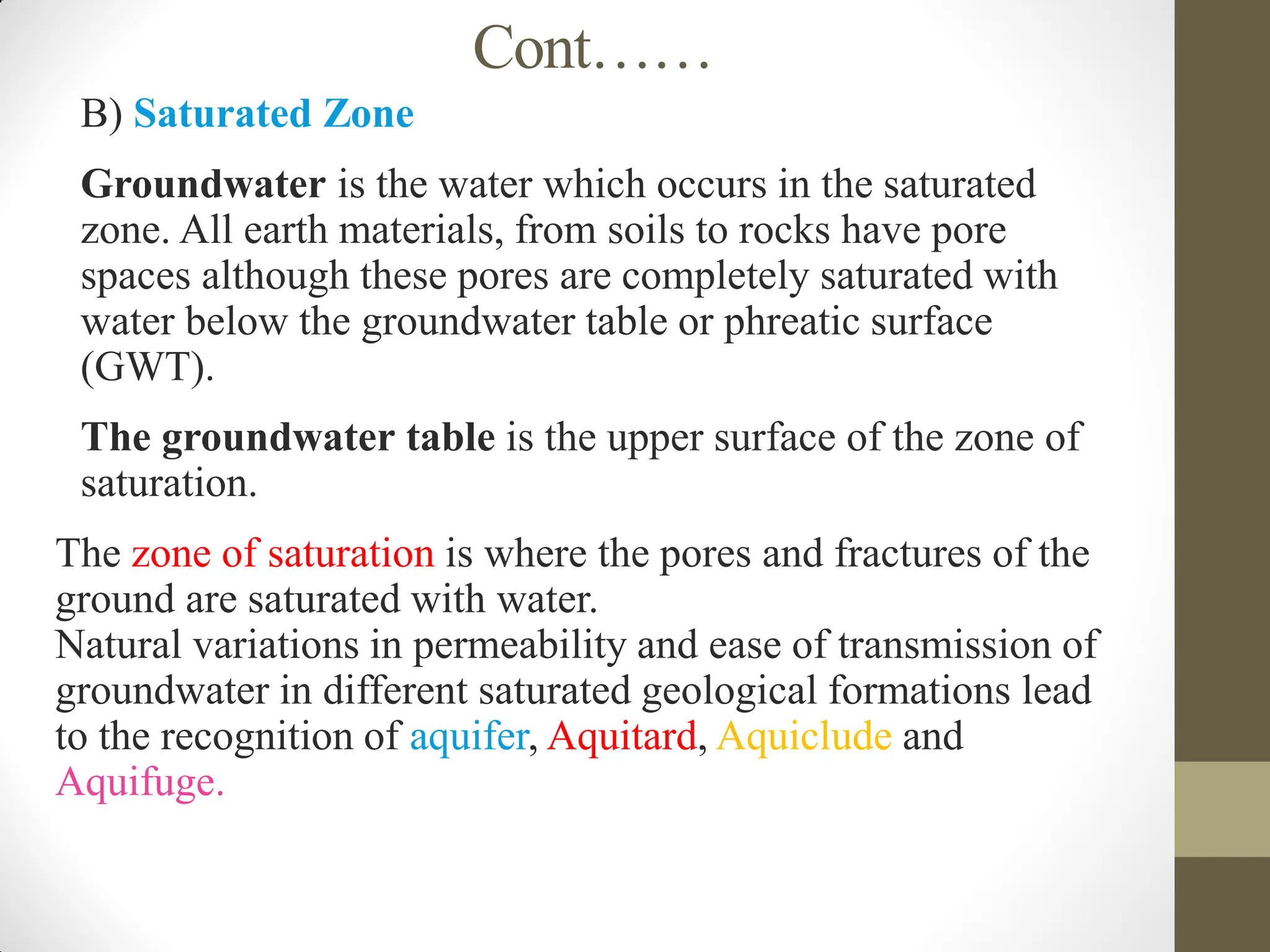
B) SaturatedZone
Groundwater is the water which occurs in the saturated
zone. All earth materials, from soils to rocks have pore
spaces although these pores are completely saturated with
water below the groundwater table or phreatic surface
(GWT).
The groundwater table is the upper surface of the zone of
saturation.
The zone of saturation is where the pores and fractures of the
ground are saturated with water.
Natural variations in permeability and ease of transmission of
groundwater in different saturated geological formations lead
to the recognition of aquifer, Aquitard, Aquiclude and
Aquifuge.
54.
Cont…...
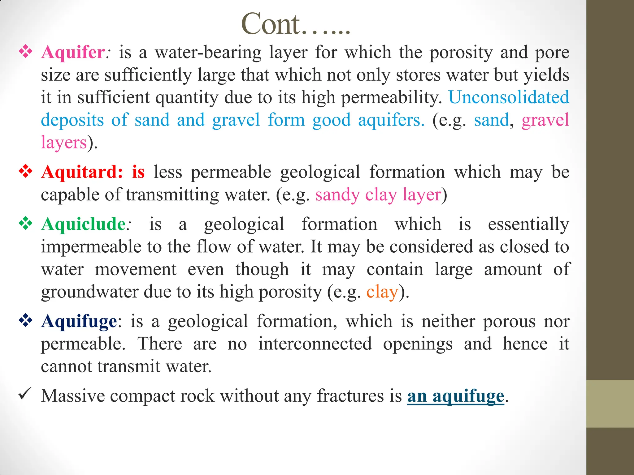
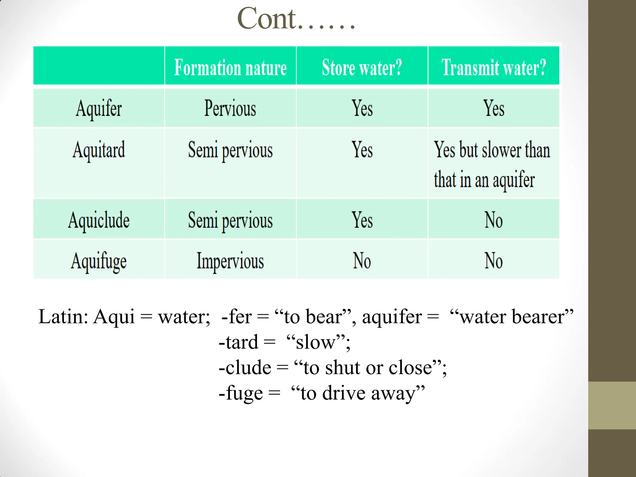
Aquifer: isa water-bearing layer for which the porosity and pore
size are sufficiently large that which not only stores water but yields
it in sufficient quantity due to its high permeability. Unconsolidated
deposits of sand and gravel form good aquifers. (e.g. sand, gravel
layers).
Aquitard: is less permeable geological formation which may be
capable of transmitting water. (e.g. sandy clay layer)
Aquiclude: is a geological formation which is essentially
impermeable to the flow of water. It may be considered as closed to
water movement even though it may contain large amount of
groundwater due to its high porosity (e.g. clay).
Aquifuge: is a geological formation, which is neither porous nor
permeable. There are no interconnected openings and hence it
cannot transmit water.
Massive compact rock without any fractures is an aquifuge.
Cont……
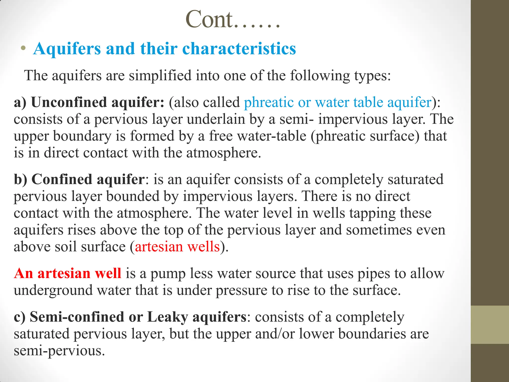
• Aquifers andtheir characteristics
The aquifers are simplified into one of the following types:
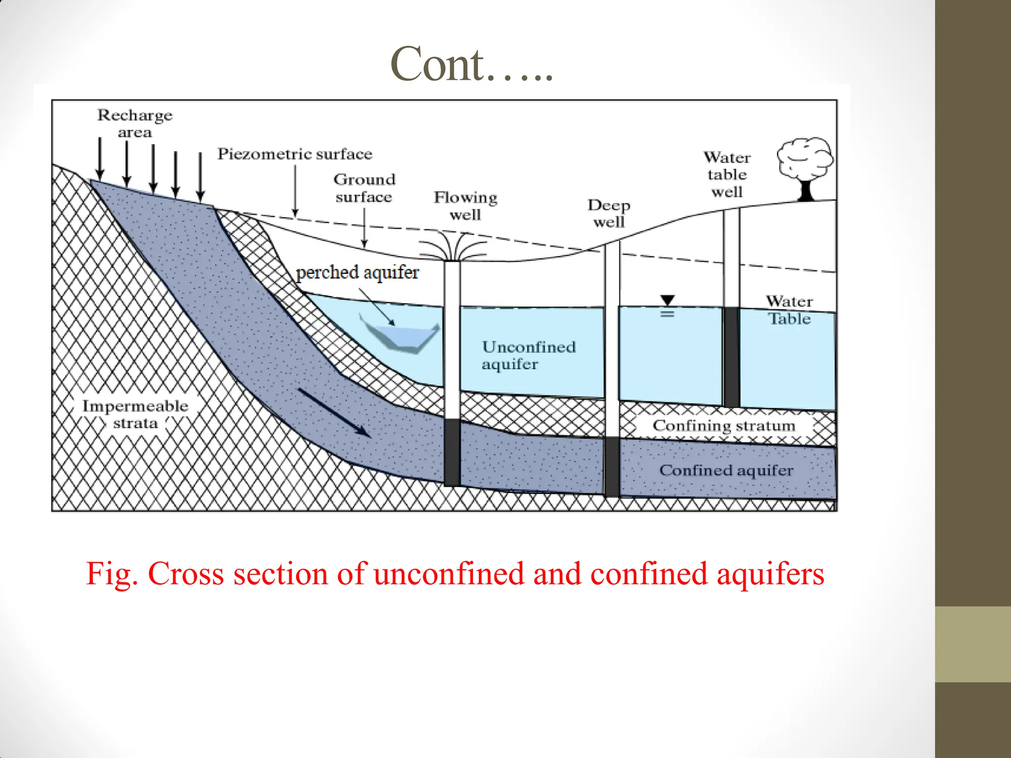
a) Unconfined aquifer: (also called phreatic or water table aquifer):
consists of a pervious layer underlain by a semi- impervious layer. The
upper boundary is formed by a free water-table (phreatic surface) that
is in direct contact with the atmosphere.
b) Confined aquifer: is an aquifer consists of a completely saturated
pervious layer bounded by impervious layers. There is no direct
contact with the atmosphere. The water level in wells tapping these
aquifers rises above the top of the pervious layer and sometimes even
above soil surface (artesian wells).
An artesian well is a pump less water source that uses pipes to allow
underground water that is under pressure to rise to the surface.
c) Semi-confined or Leaky aquifers: consists of a completely
saturated pervious layer, but the upper and/or lower boundaries are
semi-pervious.
57.
Cont…..
d) Perched aquifers:are unconfined aquifers of isolated in
nature. They are not connected with other aquifers.
The pressure of the water in an aquifer is measured with a
piezometer, which is an open ended pipe with a diameter of
3-10 cm.
Piezometer: is an instrument for measuring the pressure of
the water in the aquifer. Piezometers are often placed in
boreholes to monitor the pressure or depth of ground water.
The height to which the water rises with respect to a certain
reference level (e.g. the impervious base, mean sea level,
etc.) is called the hydraulic head.
hydraulic head(h)= z+ p/γw
where, z - the gravitational elevation head and
p/γw - pressure head.
Cont……
• Determination ofgroundwater flow parameters
The following are some of the groundwater flow parameters or
aquifer properties which are important in the storage and
transmission of water in aquifers.
1. Porosity (n): is the ratio of volume of the open space in the
rock or soil to the total volume of soil or rock.
n=Vv/Vt*100
Where, Vv = the pore volume or volume of voids
Vt = the total volume of the soil
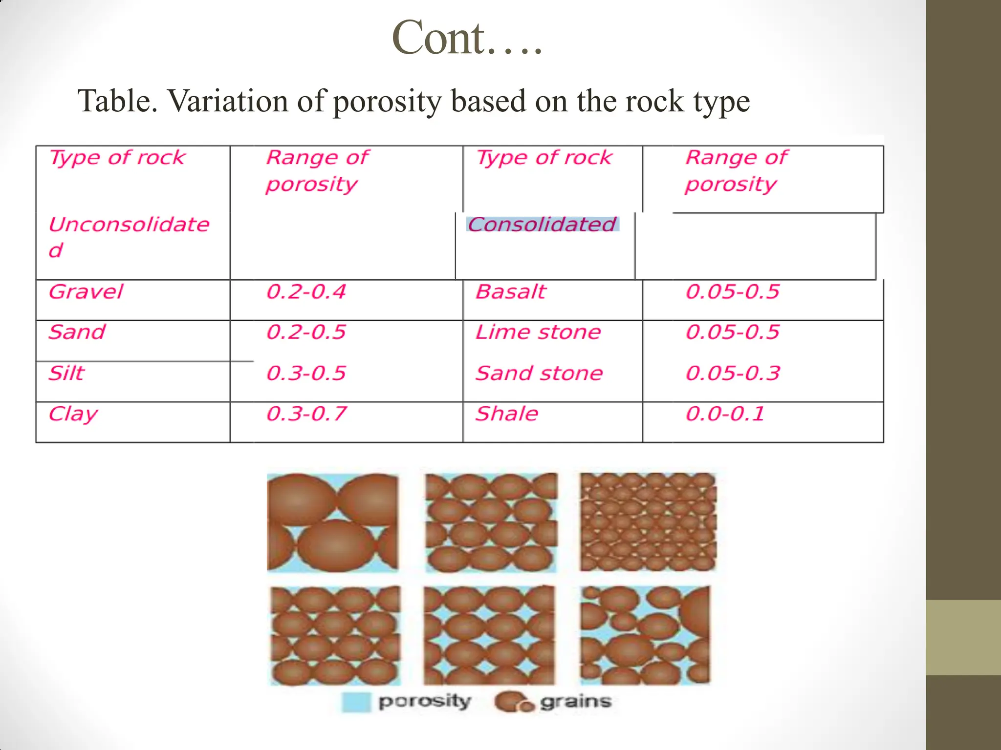
Porosity is also the measure of water holding capacity of the
geological formation. The greater the porosity means the larger is
the water holding capacity. It depends up on the shape, size, and
packing of soil particles. Porosity greater than 20% is considered
large; 5-20% medium and less than 5% is small.
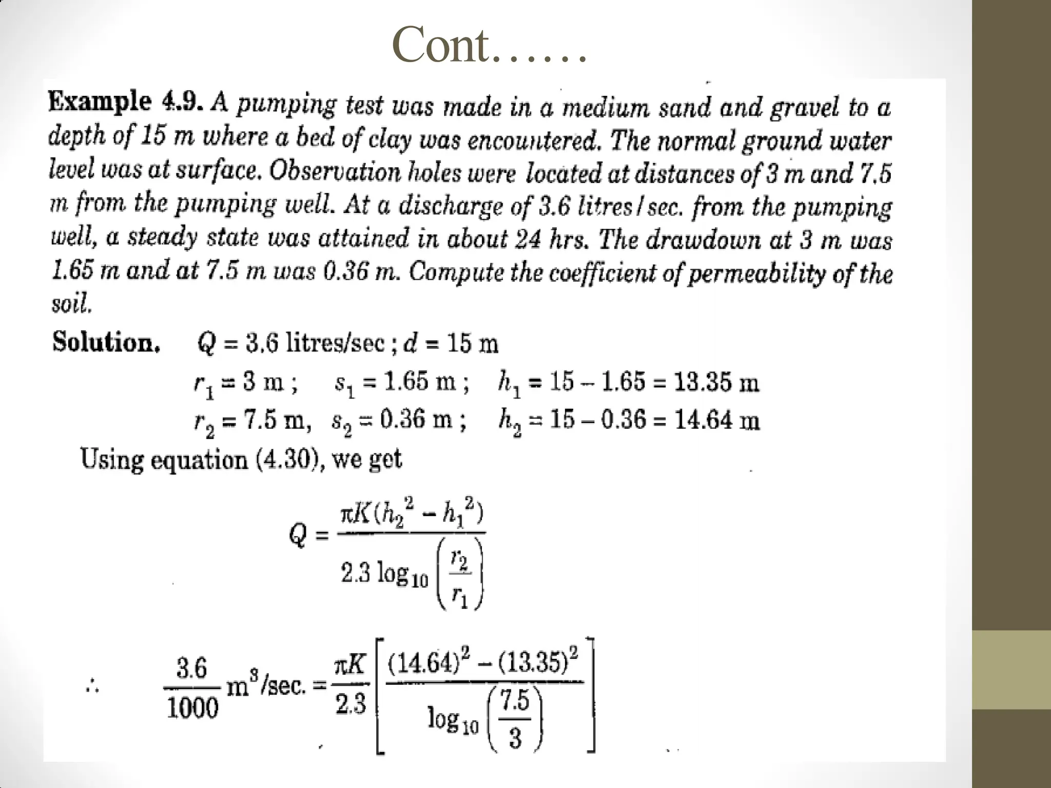
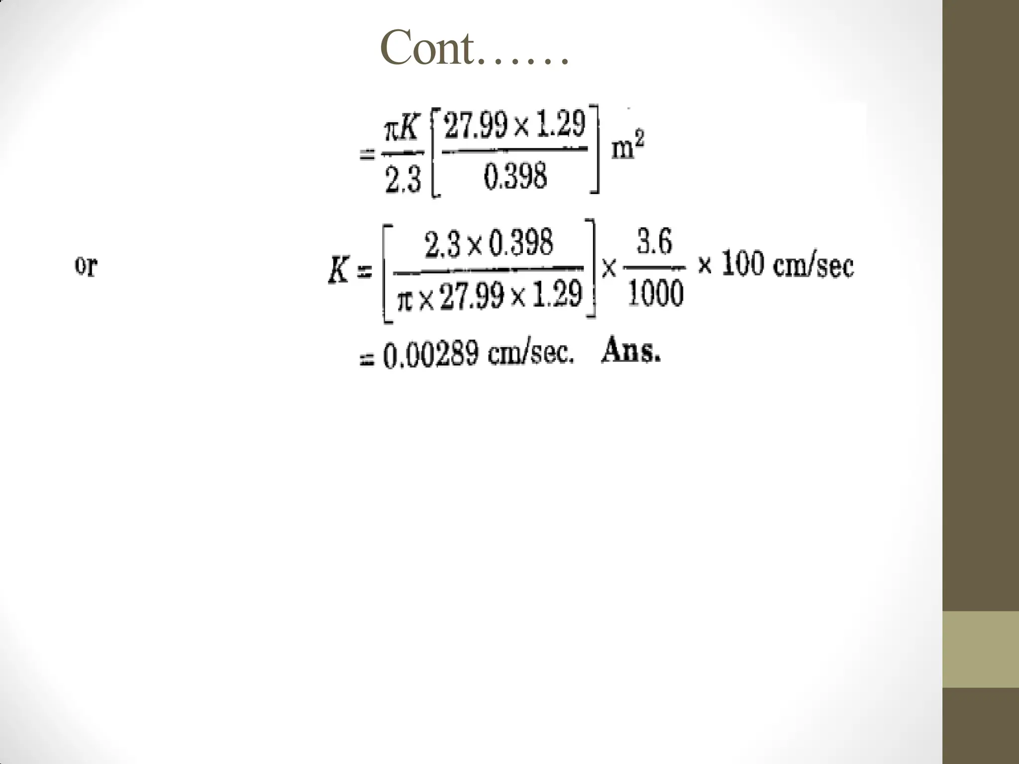
Cont…..
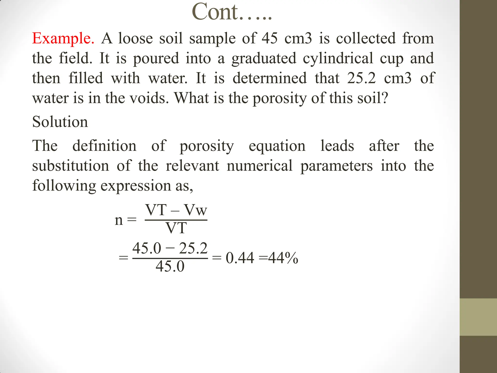
Example. A loosesoil sample of 45 cm3 is collected from
the field. It is poured into a graduated cylindrical cup and
then filled with water. It is determined that 25.2 cm3 of
water is in the voids. What is the porosity of this soil?
Solution
The definition of porosity equation leads after the
substitution of the relevant numerical parameters into the
following expression as,
n =
VT – Vw
VT
=
45.0 − 25.2
45.0
= 0.44 =44%
62.
Cont…..
2. Specific yield(Sy)
When water is drained by gravity from saturated material, only a
part of the total volumes is released. The ratio of volume of water in
the aquifer which can be extracted by the force of gravity or by
pumping wells to the total volume of saturated aquifer is called
Specific yield (Sy). Sy=Vw/Vt*100
Where:
Sy= Specific yield
Vw=the volume of extractible water
Vt = the total volume of the soil
All the water stored in the water bearing formations can’t be
extracted by gravity drainage or pumping; a portion of water
remains held in the voids of the aquifer by molecular and surface
tension forces.
For unconfined aquifers, the specific yield (Sy) is defined as the
amount of water stored or released in an aquifer column with a
cross-sectional area of 1square meter as a result of a 1m increase or
decrease in hydraulic head.
63.
Cont…..
3. Specific retention(Sr)
The water which is not drained or the ratio of volume of water that
cannot be drained (Vr) to the total volume (VT) of a saturated
aquifer is called specific retention (Sr).
Sr=Vr/Vt*100
In fine-grained material the forces that retain water against the
force of gravity are high due to the small pore size. Hence, the
specific retention of fine-grained material (silt or clay) is larger
than that of coarse material (sand or gravel).
The total volume of voids (Vv) equals to the sum of volume of
water drained out (Vw) and volume of water retained (Vr).
Vv=Vw+Vr
From the above expression we can get:
n = Vv/Vt*100=Vw/Vt*100+Vr/Vt*100 =Sy+Sr
Meaning sum of Sy and Sr is equal to the porosity. It should be
noted that;
• It is not necessarily the soil with a high porosity will have a
high specific yield because of its permeability.
64.
Cont……
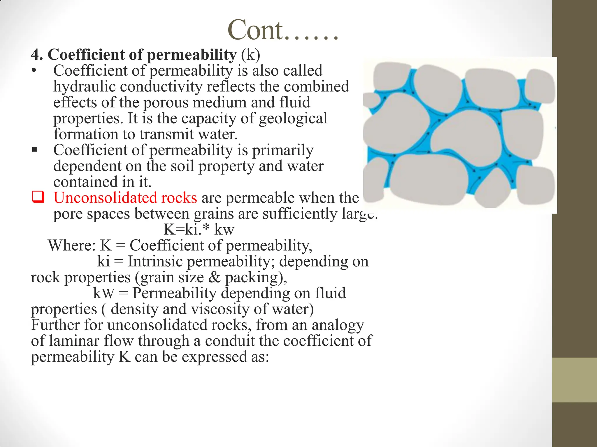
4. Coefficient ofpermeability (k)
• Coefficient of permeability is also called
hydraulic conductivity reflects the combined
effects of the porous medium and fluid
properties. It is the capacity of geological
formation to transmit water.
Coefficient of permeability is primarily
dependent on the soil property and water
contained in it.
Unconsolidated rocks are permeable when the
pore spaces between grains are sufficiently large.
K=ki.* kw
Where: K = Coefficient of permeability,
ki = Intrinsic permeability; depending on
rock properties (grain size & packing),
kW = Permeability depending on fluid
properties ( density and viscosity of water)
Further for unconsolidated rocks, from an analogy
of laminar flow through a conduit the coefficient of
permeability K can be expressed as:
65.
Cont……
𝑘=𝑐𝑑𝑚2
(ℽ/µ)=𝑐𝑑𝑚2
("ρ g/" µ)Where dm = Mean pore size of
the porous medium (m),
µ= dynamic viscosity of the fluid (kg/m.s),
ρ= density of the fluid (kg/𝑚3
),
ℽ= unit weight of the fluid (kg/𝑚2𝑠2)
g = acceleration due to gravity (m/𝑠2
)
C = a shape factor which depends on the porosity,packing,
shape of grains and grain-size distribution of the porous medium.
Thus, for a given porous material K α1/v where, v = kinematic
viscosity = µ/ ρ
5. Storage Coefficient (S)
The amount of water stored or released in an aquifer column
with a cross sectional area of 1 meter square for a 1m increase
or drop in head is known as storage coefficient. Storage
coefficient of unconfined aquifer is equal to the specific yield.
Because most of the water from storage is released by the
action of gravity with negligible part from the compression of
the aquifer and the expansion of the water.
Storativity is developed primarily for the analysis of well
hydraulics in a confined aquifer.
66.
Cont……
In confinedor semi-confined aquifers water is stored or released
from the whole aquifer column mainly as a result of elastic
changes in porosity and groundwater density.
• Common values for the storage coefficients for confined and
semi-confined aquifers range form 10−7 𝑡𝑜 10−3.
The volume of water drained from an aquifer, Vw may be
found from the following equation. Vw=SA h
where, A is horizontal area and
h is fall in head
6. Specific Storage (Ss)
Specific storage, often denoted by the symbol "Ss," is a measure
of the amount of water that an aquifer releases from storage per
unit volume of the aquifer per unit change in hydraulic head.
67.
Cont……
• Specific storagetakes into account the compressibility or expansibility of
the aquifer material. It reflects the ability of the aquifer to release water
when subjected to changes in hydraulic head, considering both the
porosity and compressibility of the aquifer material.
• It is also the storage coefficient per unit saturated thickness of an
aquifer.
For confined aquifer, the relation between the specific storage and the
storage coefficient is as follows:
Ss =
∆𝑉𝑤𝑎𝑡𝑒𝑟
𝑣𝑎𝑞𝑢𝑖𝑓𝑒𝑟∗∆ℎ
S = Ss*b
Where:
S = Storage coefficient (dimensionless),
b = aquifer thickness (m)
• Specific Storage is also called elastic storage coefficient and is
given by the following expression.
Ss= ρg ( α+nβ )
Where:
ρ =fluid (water) density,
g=gravitational acceleration,
α =aquifer compressibility,
n= porosity,
β =water compressibility
68.
Cont……
• DESIGN OFWATER WELL
water well is a hole or shaft, in most cases, vertical
excavated in the earth or sunk into the ground intercepting
one or more water bearing strata, for bringing ground water
to the surface.
Objectives of water well is:
- To provide water with good quality.
- To provide water at low cost.
- To provide sufficient quantity of water.
- To provide water for long time.
69.
Cont…...
• CLASSIFICATION OFWATER WELL
Wells can be classified as their methods of construction (dug
well and tube well), their depth (shallow and deep well) and
whether they are vertical or horizontal.
1. Dug well: is a traditional method of obtaining water which
is a shallow hole dug down into the water table.
2. Tube wells: are developed to increases their specific
capacity, prevent sanding and obtain maximum economic well
life.
Observation well is used to monitor important hydrologic
parameters in a geothermal system that can indicate
performance, longevity, and transient processes.
70.
Cont…..
Transmissivity (T) =KB
where, K= hydraulic conductivity
B= aquifer thickness
• Hydraulic conductivity (K): This term refers to the ability of a
porous medium to transmit water under a hydraulic gradient.
• Transmissivity (T): Transmissivity, on the other hand, is a measure
of the capacity of an aquifer to transmit water through its entire
thickness.
• This equation shows that h increases as r increases. Yet, the
maximum h is the initial uniform H. Thus, from theoretical point of
view, steady radial flow in an extensive aquifer does not exist b/c the
cone of depression must expand indefinitely with time. However,
from practical stand point, h approaches ho with distance from the
well, and the drawdown vary with the logarithm of the distance from
the well.
71.
Cont…..
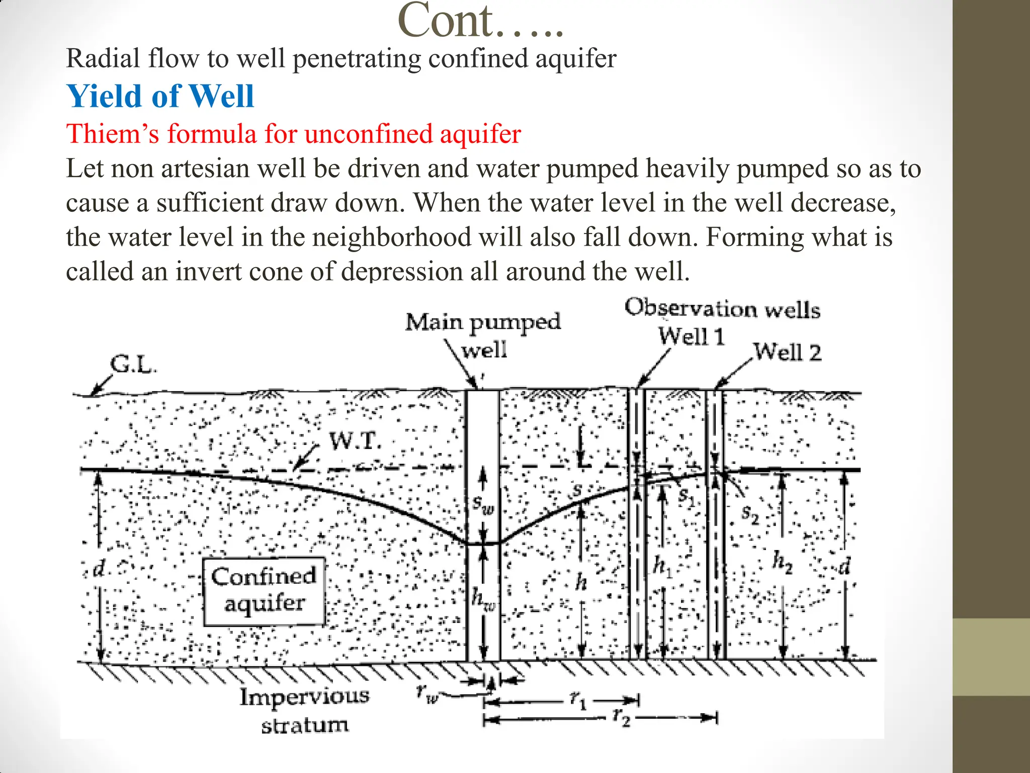
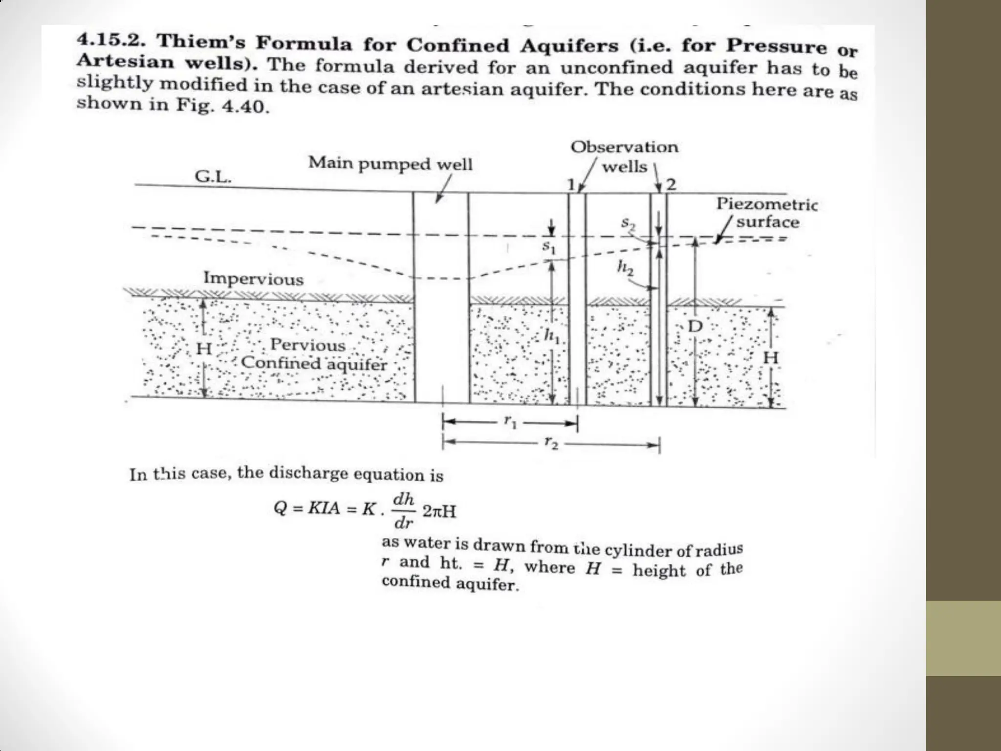
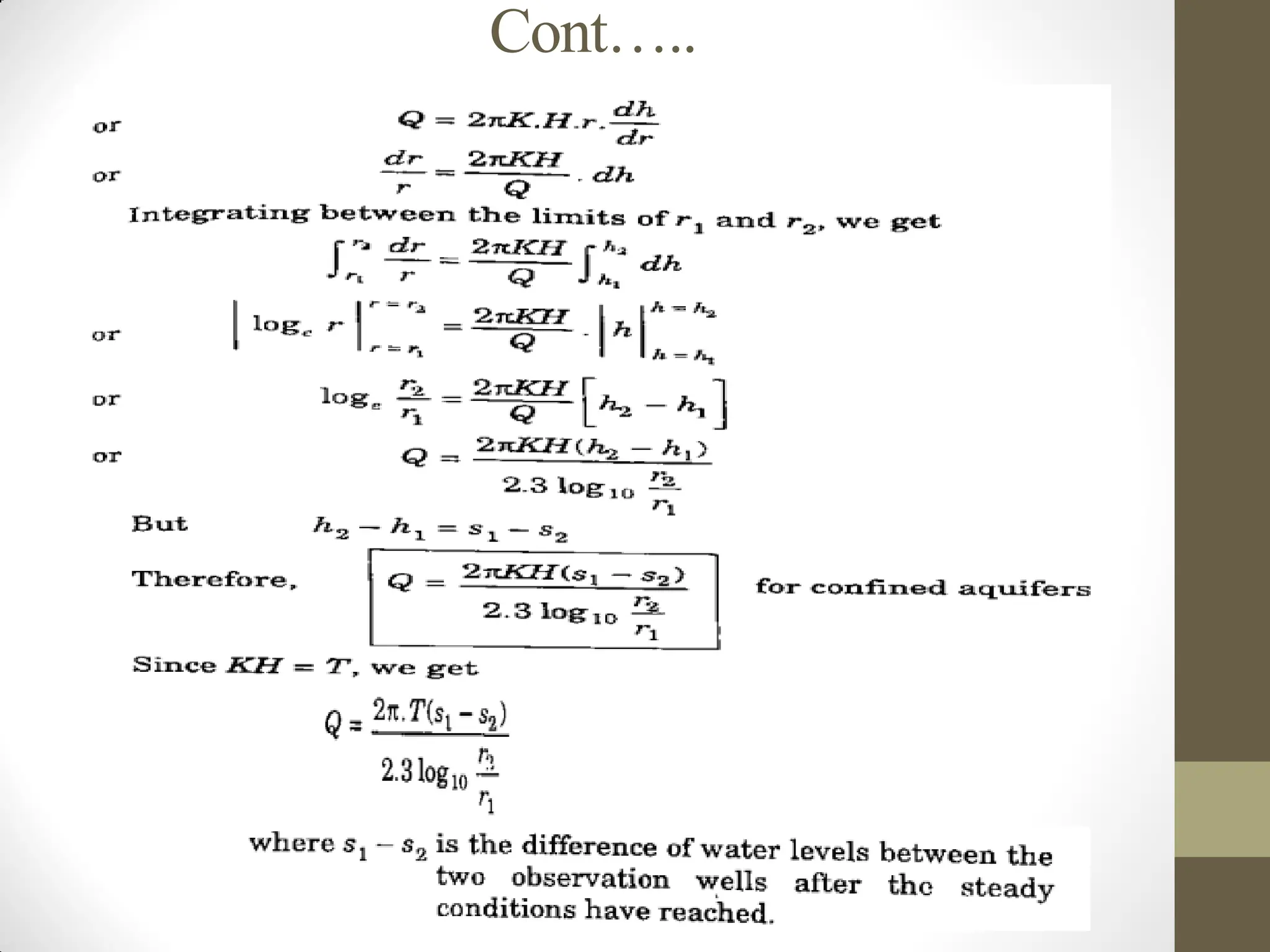
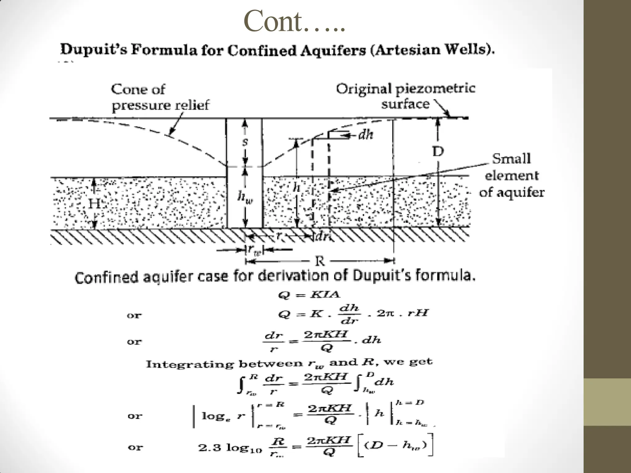
Radial flow towell penetrating confined aquifer
Yield of Well
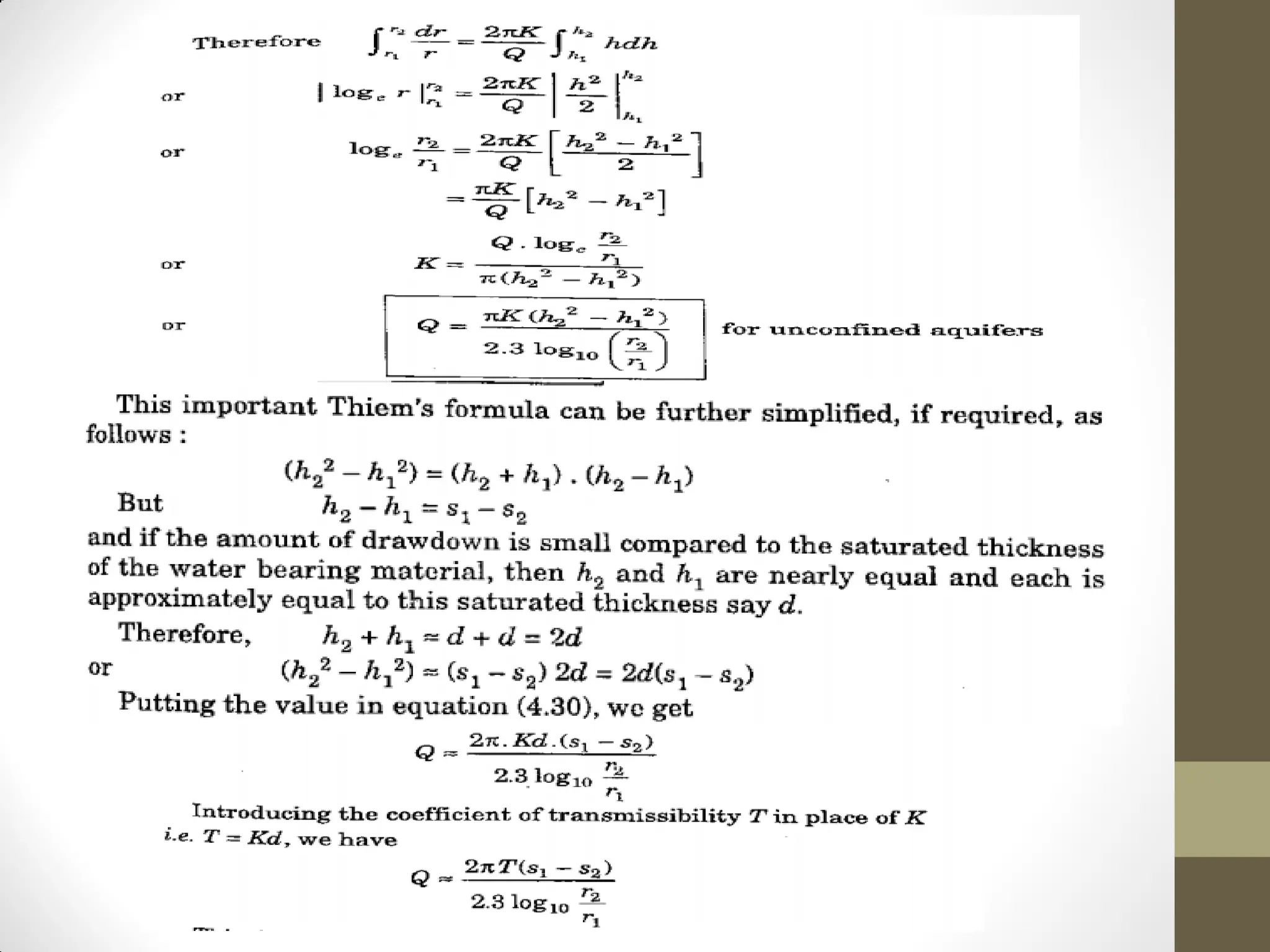
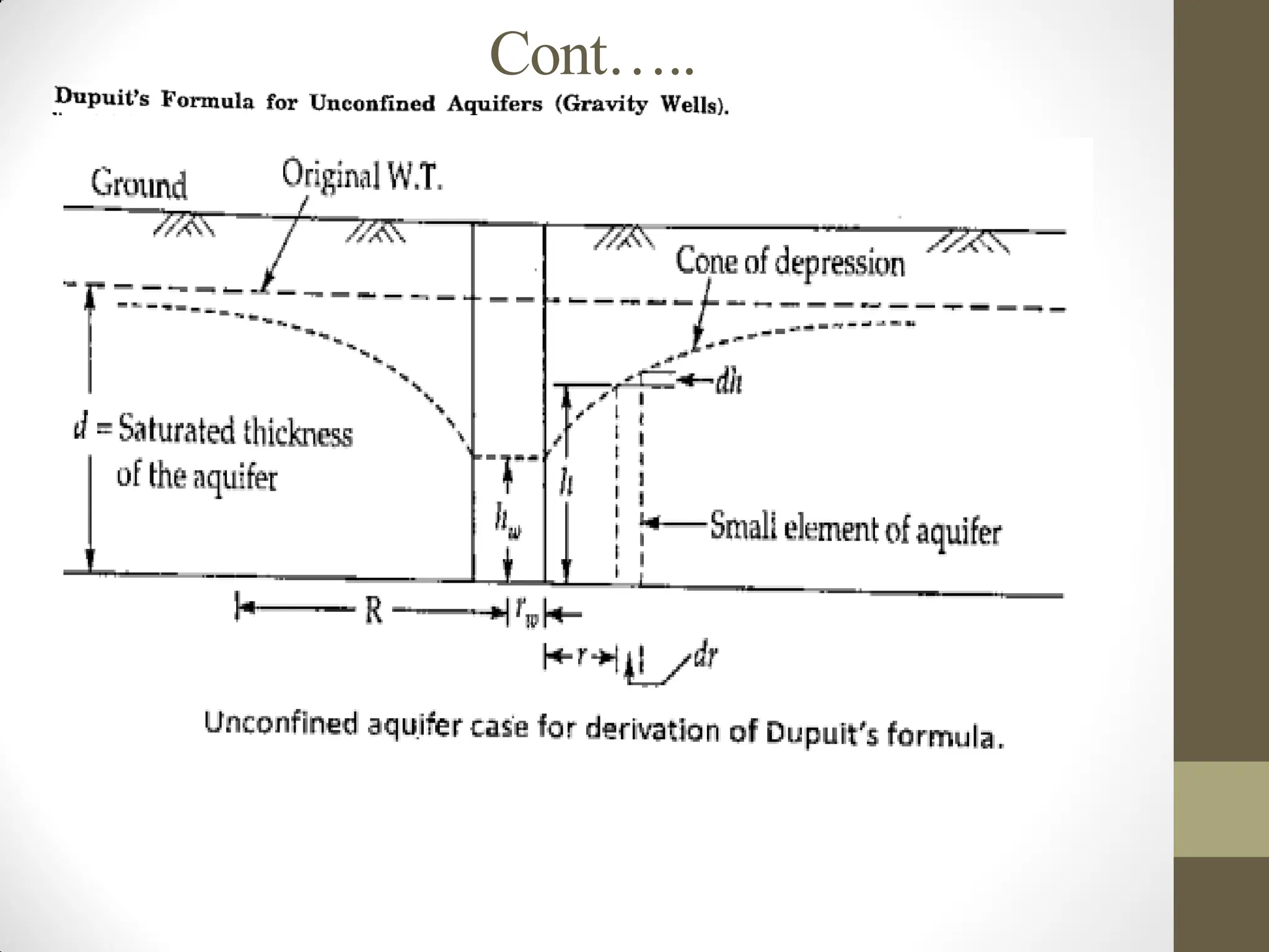
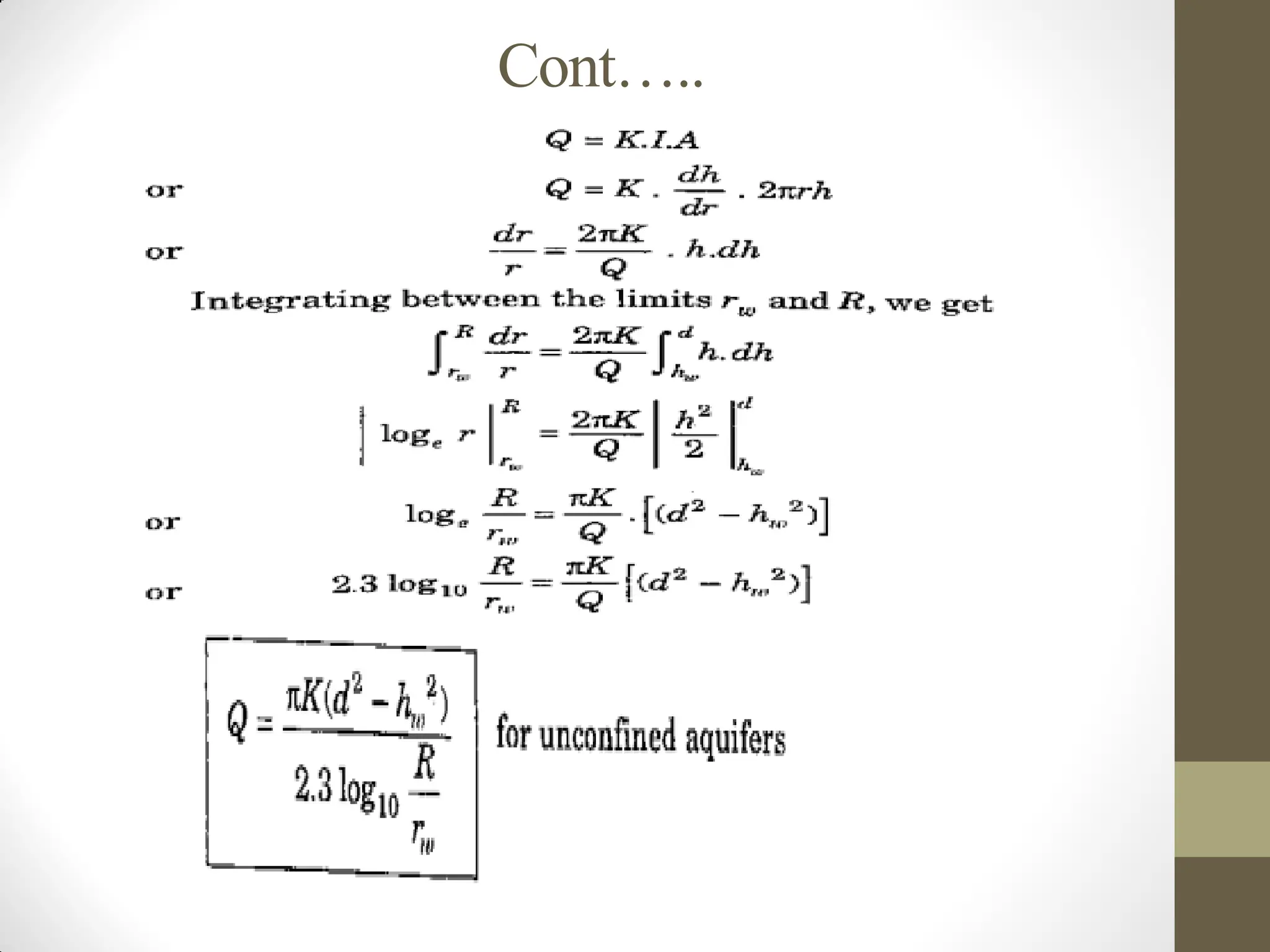
Thiem’s formula for unconfined aquifer
Let non artesian well be driven and water pumped heavily pumped so as to
cause a sufficient draw down. When the water level in the well decrease,
the water level in the neighborhood will also fall down. Forming what is
called an invert cone of depression all around the well.
Cont…..
Piezometric surface/potentiometricsurface: is the
imaginary surface to which groundwater rises under
hydrostatic pressure in wells or springs.
Drawdown curve: plot of the decline of water table or
piezometric level versus distance from a pumping well, or
versus time at a given distance from a pumping well,
resulting from the continuous pumping from a well
discharging at a known rate.
Radius of Influence(R) means the radial distance from the
center of a well bore to the point where there is no lowering
of the water table or potentiometric surface because of
pumping of the well; the edge of the cone of depression.
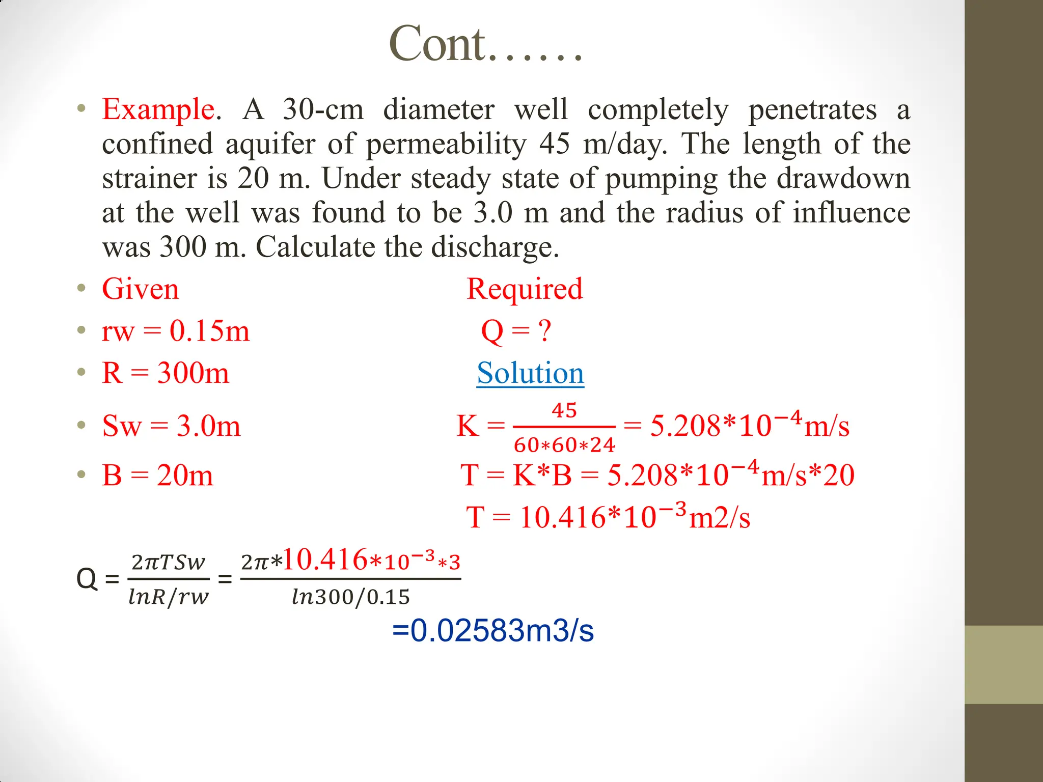
Cont……
• Example. A30-cm diameter well completely penetrates a
confined aquifer of permeability 45 m/day. The length of the
strainer is 20 m. Under steady state of pumping the drawdown
at the well was found to be 3.0 m and the radius of influence
was 300 m. Calculate the discharge.
• Given Required
• rw = 0.15m Q = ?
• R = 300m Solution
• Sw = 3.0m K =
45
60∗60∗24
= 5.208*10−4m/s
• B = 20m T = K*B = 5.208*10−4
m/s*20
T = 10.416*10−3m2/s
Q =
2𝜋𝑇𝑆𝑤
𝑙𝑛𝑅/𝑟𝑤
=
2𝜋∗10.416∗10−3∗3
𝑙𝑛300/0.15
=0.02583m3/s
84.
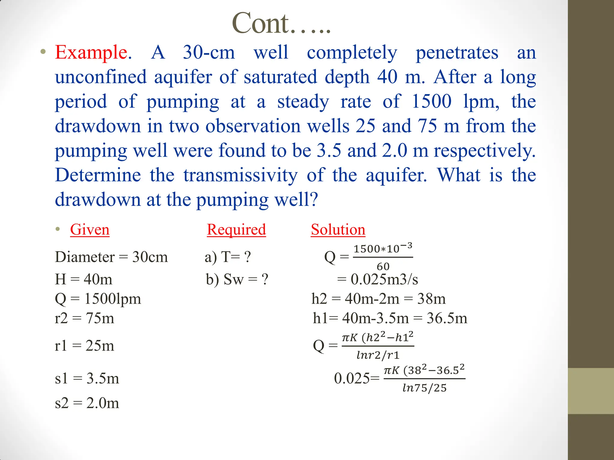
Cont…..
• Example. A30-cm well completely penetrates an
unconfined aquifer of saturated depth 40 m. After a long
period of pumping at a steady rate of 1500 lpm, the
drawdown in two observation wells 25 and 75 m from the
pumping well were found to be 3.5 and 2.0 m respectively.
Determine the transmissivity of the aquifer. What is the
drawdown at the pumping well?
• Given Required Solution
Diameter = 30cm a) T= ? Q =
1500∗10−3
60
H = 40m b) Sw = ? = 0.025m3/s
Q = 1500lpm h2 = 40m-2m = 38m
r2 = 75m h1= 40m-3.5m = 36.5m
r1 = 25m Q =
𝜋𝐾 (ℎ22−ℎ12
𝑙𝑛𝑟2/𝑟1
s1 = 3.5m 0.025=
𝜋𝐾 (382−36.52
𝑙𝑛75/25
s2 = 2.0m
85.
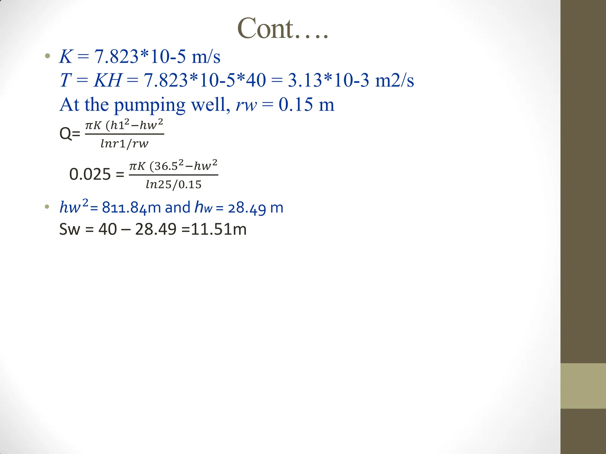
Cont….
• K =7.823*10-5 m/s
T = KH = 7.823*10-5*40 = 3.13*10-3 m2/s
At the pumping well, rw = 0.15 m
Q=
𝜋𝐾 (ℎ12−ℎ𝑤2
𝑙𝑛𝑟1/𝑟𝑤
0.025 =
𝜋𝐾 (36.52−ℎ𝑤2
𝑙𝑛25/0.15
• ℎ𝑤2
= 811.84m and hw = 28.49 m
Sw = 40 – 28.49 =11.51m
86.
Cont…..
Design parameters ofwell
The design parameters of well and collection system are based on the
information and data described below.
- Geological and geo-morphological studies of the well field
- Hydro-geological and geo-physical investigation reports
- Inventory and evaluation of existing wells
87.
Cont…..
1. Casing diameter
The size of casing diameter should be properly choosing
since it significantly affects the cost of the construction.
The diameter of casing is choosing to satisfy three
requirements: -
- It must be sufficient to accommodate the required
discharge from the well
- The casing must be large enough for installation and
efficient operation of the pump with enough clearance
- It must be sufficient to assure that the up-hole velocity is
equal to 1.5m/s or less.
88.
Cont……
Check velocity forthe sufficient of the casing
Q=AV
where A=area of casing
D= diameter of casing
Q=required discharge
V=up borehole velocity=Q/A
The velocity must be less than 1.5m/s.
2. Well diameter
• To facilitate the lowering of the casing pipe the diameter of the
well has to be at least 5cm bigger in diameter than the casing.
Well diameter=casing diameter+(5-15cm)
3. Well depth
• The depth of a tube well depends up on the locations of water
bearing formations, desired yields of the well and economic
considerations.
• The well is usually drilling up to the bottom of the aquifer so
that aquifer thickness is available, permitting greater well
yield.
89.
Cont……
4. Thickness ofaquifer
• The investigation of water wells is carrying out very close to
the matured river valley at the eastern side of the town, and
considerable thickness, about 60 meters of low resistivity layer
is finds below 15 meters. This indicates that the static water
level in the aquifer b/n 15m and 60m below the ground level.
Therefore, it is advisable to drill the wall more than depth of
60m to have a continuous yield of water.
Thickness of aquifer=15m - 60m
5. Water well screen
It is usually a pipe with slots or openings along its wall. A filter
device serves as the intake component of a constructed well.
It is uses to:
Permits water to enter the well from the saturated aquifer
Allows a maximum amount of water to enter the well with a
minimum hydraulic resistance
Prevents sand movement from entering into the well
90.
Cont…..
The basic requirementsof a well screen are:
It should be resistant to corrosion and deterioration, strong
enough to prevent collapse of a hole
It should no clogging in slots
It should have enough percentage of open area to enter the
water
Water well screen includes well screen length, diameter of well
screen, size and shape of open area, percentage of open area,
etc
a) Well screen length
The theory and experience have shown that screening the
bottom one-third of the aquifer thickness provides optimum
design.
well screen length=1/3*aquifer thickness
b. Well screen diameter
• Screen diameter is select to satisfy the required demand.
Enough open area must be provided so that the entrance
velocity of the water generally not exceeds the design standard
of 3cm/s.
91.
Cont……
• To checkthe accidence of the entrance velocity from the design
standard for the recommended screen diameter size:
𝑉𝑠 =
𝑄
𝜋𝑐𝐷𝐿𝑃
where, c= clogging coefficient (estimated
approximately 0.5)
Q=required discharge in m3/s
Vs=optimum screen entrance velocity
L=screen length
D=diameter of screen
P=percentage of opening in the screen
• The optimum entrance velocity must be less than the maximum
design standard of 3cm/s.
c. Well screen slot openings
• The size of the slot opening is determining by the size of gravel
pack or aquifer material; which the screen has to retain.
92.
Cont……
The volume offilter pack required(V)=
π 𝐷𝑔2 − 𝐷𝑤2
4
Where, Dg=diameter of gravel packed
Dw=diameter of well
𝑔𝑟𝑎𝑣𝑒𝑙 𝑡ℎ𝑖𝑐𝑘𝑛𝑒𝑠𝑠 =
𝐷𝑔 − 𝐷𝑠
4
where, Ds=screen diameter
• Gravel thickness must be greater than 7.5cm the minimum
recommended thickness.