This Security Mechanisms and Techniques presentation, explores the fundamental methods used to protect digital systems and data from threats. It delves into key security principles such as authentication, encryption, access control, and intrusion detection. The chapter provides an overview of cryptographic techniques, including symmetric and asymmetric encryption, hashing, and digital signatures, which ensure data confidentiality and integrity. Additionally, it discusses authentication methods like passwords, biometrics, and multi-factor authentication, emphasizing their role in verifying user identities and preventing unauthorized access.
Beyond encryption and authentication, the chapter examines access control models, including discretionary, mandatory, and role-based access control, which regulate user permissions within a system. It also covers intrusion detection and prevention systems, firewalls, and security protocols that safeguard networks and applications. The importance of secure software development, patch management, and regular security audits is highlighted to mitigate vulnerabilities. Overall, this chapter provides a comprehensive understanding of security mechanisms that form the foundation of modern cybersecurity strategies.

![7
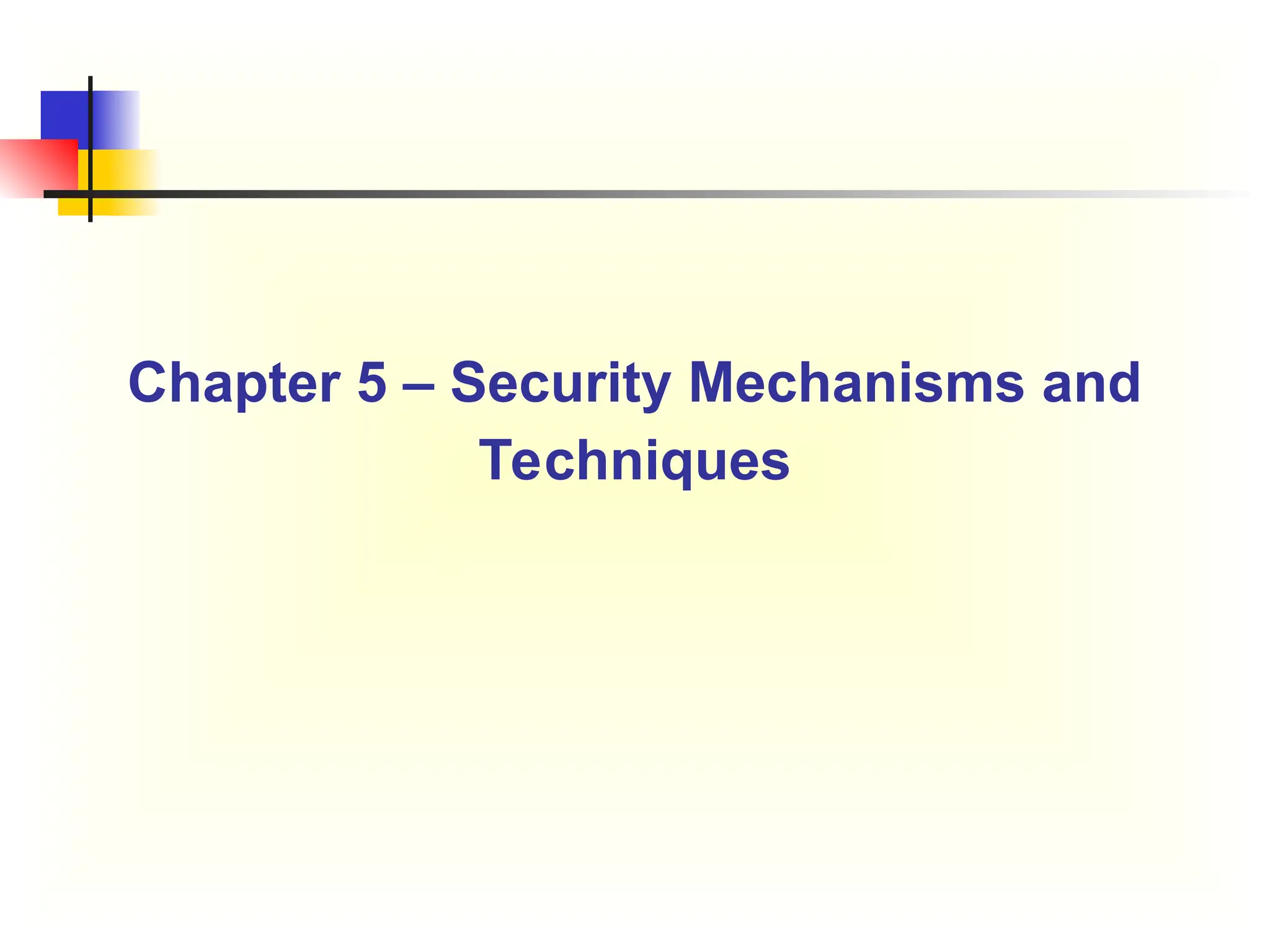
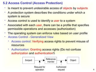
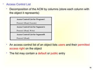
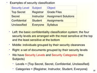
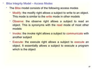
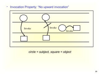
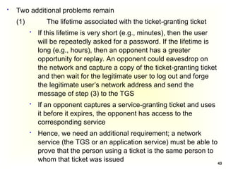
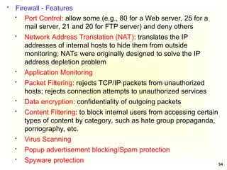
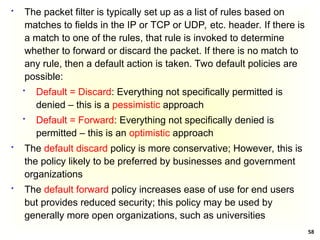
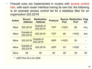
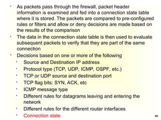
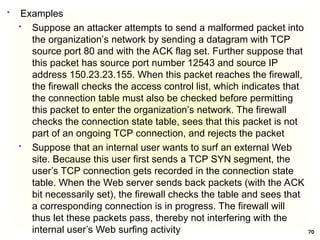
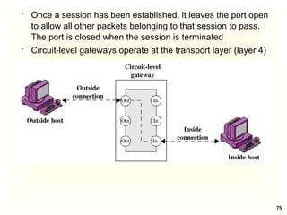
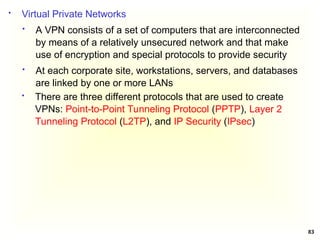
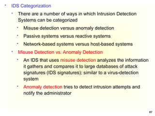
Access Control Matrix
Subject Object
In the ACM, each subject is represented by a row and each
object as a column
Capabilities: are stored row-wise - with the subjects
Permissions: are stored column-wise - with the objects
ACM [s, o] lists precisely which operations subject s can
request to be carried out on object o](https://image.slidesharecdn.com/chapter5-securitymechanismsandtechniques-250221044504-d17b5c81/85/Chapter-5-Security-Mechanisms-and-Techniques-ppt-7-320.jpg)


![38
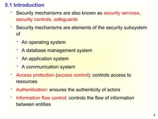
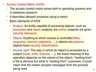
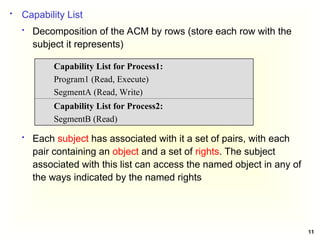
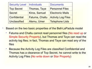
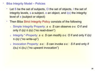
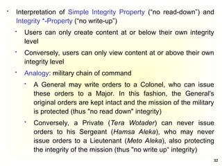
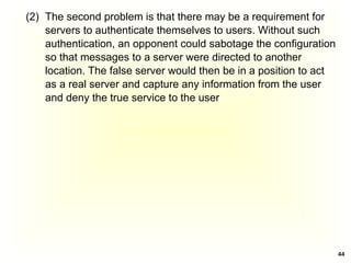
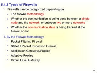
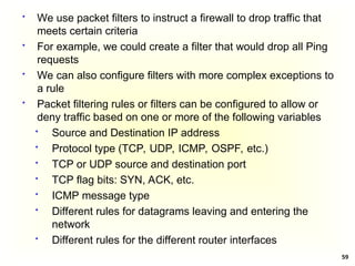
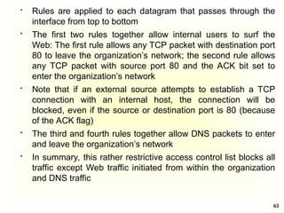
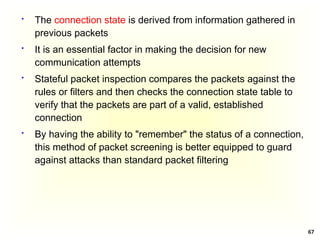
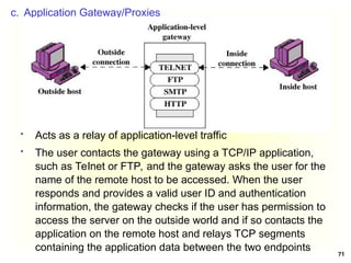
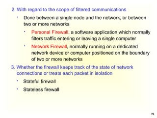
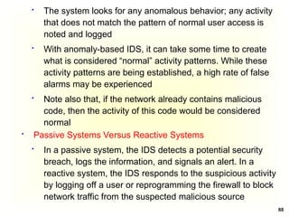
A Simple Authentication Dialogue; the user logs on to a
workstation and requests access to server V (3 steps)
(1) C AS: IDc || Pc || IDv
The client module C in the user’s workstation requests the
user’s password and then sends a message to the AS that
includes the user’s ID, the user’s password, and the
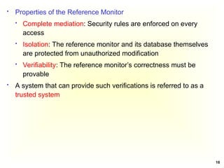
server’s ID
(2) AS C: Ticket
The AS checks its database to see if the user has supplied
the proper password for this user ID and whether this user
is permitted access to server V; then the AS creates a
ticket that contains the user’s ID and network address and
the server’s ID
Ticket = E(Kv, [IDc || ADc || IDv])
The ticket is encrypted using the secret key shared by the
AS and the server](https://image.slidesharecdn.com/chapter5-securitymechanismsandtechniques-250221044504-d17b5c81/85/Chapter-5-Security-Mechanisms-and-Techniques-ppt-38-320.jpg)
![40
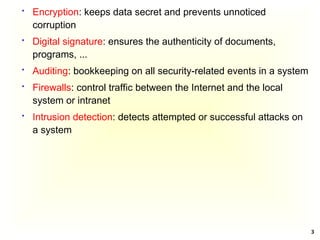
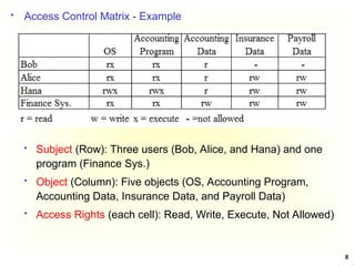
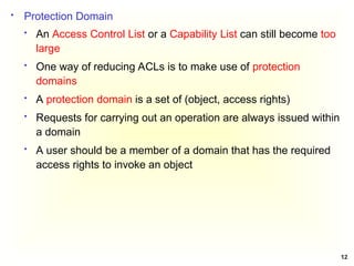
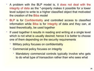
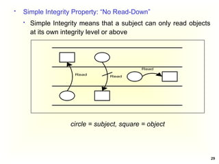
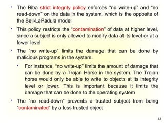
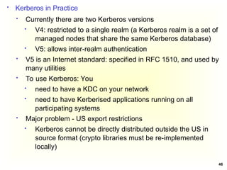
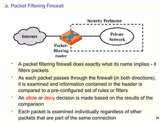
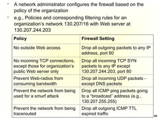
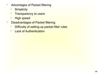
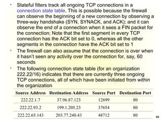
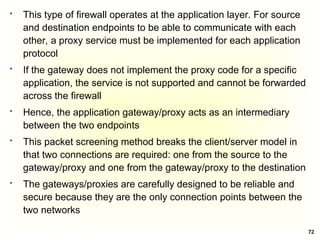
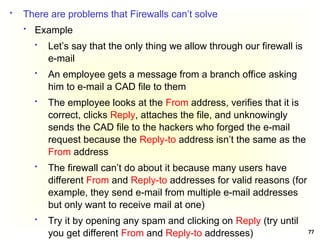
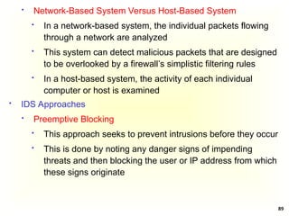
A More Secure Authentication Dialogue
Once per user login session
(1) C AS: IDc || IDtgs
The client requests a ticket-granting ticket (Tickettgs) on
behalf of the user by sending its user’s ID to the AS,
together with the TGS ID, indicating a request to use the
TGS service
(2) AS C: E(Kc, Tickettgs)
Tickettgs = E(Ktgs, [IDc||ADc||IDtgs||TS1|| Lifetime1])
The AS responds with a ticket that is encrypted with a key
that is derived from the user’s password (KC), which is
already stored at the AS
When the response arrives at the client, the client prompts
the user for his/her password, generates the key (Kc), and
attempts to decrypt the incoming message. If the correct
password is supplied, the ticket is successfully recovered
and saved](https://image.slidesharecdn.com/chapter5-securitymechanismsandtechniques-250221044504-d17b5c81/85/Chapter-5-Security-Mechanisms-and-Techniques-ppt-40-320.jpg)
![42
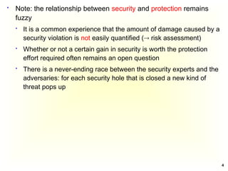
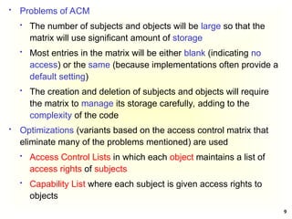
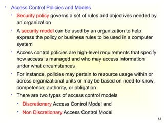
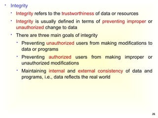
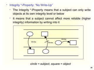
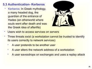
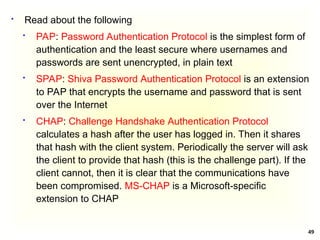
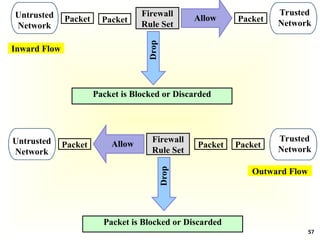
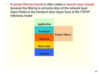
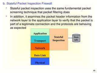
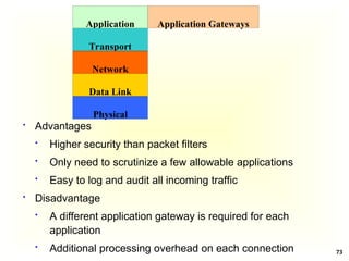
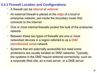
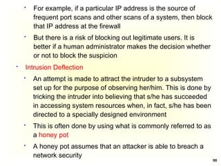
(4) TGS C: Ticketv
Ticketv = E(Kv, [IDc||ADc||IDv ||TS2|| Lifetime2]
The TGS decrypts the incoming ticket (of step 3) using Ktgs
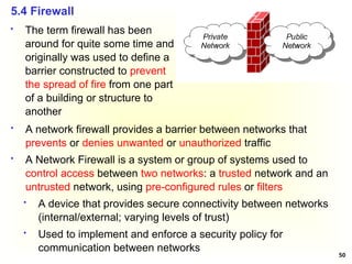
and verifies the success of the decryption by the presence of
its ID. It checks to make sure that the lifetime has not expired.
Then it compares the user ID and network address with the
incoming information to authenticate the user. If the user is
permitted access to the server V, the TGS issues a ticket to
grant access to the requested service
The client saves each service-granting ticket (Ticketv) and
uses it to authenticate its user to a server each time a
particular service is requested
Once per service session
(5) C V: IDc || Ticketv
The client requests access to a service on behalf of the user. It
transmits a message to the server containing the user’s ID and
the service granting ticket. The server authenticates by using
the contents of the ticket](https://image.slidesharecdn.com/chapter5-securitymechanismsandtechniques-250221044504-d17b5c81/85/Chapter-5-Security-Mechanisms-and-Techniques-ppt-42-320.jpg)
![45
Kc,tgs Session key accessible to client created by AS
to permit secure exchange between client and
TGS without requiring them to share a
permanent key
TS2 Informs client of time this ticket was issued
Lifetime2 Informs client of the lifetime of this ticket
Kerberos V4 Authentication Dialogue
Authentication Service Exhange: To obtain Ticket-Granting
Ticket
(1) C AS: IDc || IDtgs ||TS1
TS1 Allows AS to verify that client’s clock is synchronized
with that of AS
(2) AS C: E(Kc, [Kc,tgs|| IDtgs || TS2 || Lifetime2 || Tickettgs])
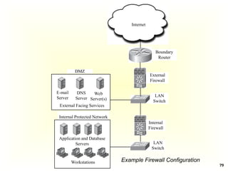
Tickettgs = E(Ktgs, [Kc,tgs||IDc||ADc||IDtgs||TS2||Lifetime2])](https://image.slidesharecdn.com/chapter5-securitymechanismsandtechniques-250221044504-d17b5c81/85/Chapter-5-Security-Mechanisms-and-Techniques-ppt-45-320.jpg)
![46
Ticket-Granting Service Echange: To obtain Service-Granting
Ticket
(3) C TGS: IDv ||Tickettgs ||Authenticatorc
Authenticatorc = E(Kc,tgs, [IDc||ADc||TS3]) - Generated by
client to validate ticket
TS3 Informs TGS of time this authenticator was
generated
Kc,v Session key accessible to client created by TGS
to permit secure exchange between client and
server without requiring them to share a
permanent key
TS4 Informs client of time this ticket was issued
(4) TGS C: E(Kc,tgs, [Kc,v|| IDv || TS4 || Ticketv])
Ticketv = E(Kv, [Kc,v||IDc||ADc||TS4||Lifetime4])](https://image.slidesharecdn.com/chapter5-securitymechanismsandtechniques-250221044504-d17b5c81/85/Chapter-5-Security-Mechanisms-and-Techniques-ppt-46-320.jpg)
![47
Client/Server Authentication Exhange: To Obtain Service
(5) C V: Ticketv || Authenticatorc
Authenticatorc = E(Kc,v, [IDc || ADc || TS5])
The server decrypts the ticket, recovers the session
key, and decrypts the authenticator
(6) V C: E(Kc,v, [TS5 +1]) (Step for mutual authentication)
The server returns the value of the timestamp from the
authenticator, incremented by 1, and encrypted using
the session key. C can decrypt this message to recover
the incremented timestamp. Because the message was
encrypted by the session key, C is assured that it could
have been created only by V. The contents of the
message assure C that this is not a replay of an old
reply](https://image.slidesharecdn.com/chapter5-securitymechanismsandtechniques-250221044504-d17b5c81/85/Chapter-5-Security-Mechanisms-and-Techniques-ppt-47-320.jpg)


![Security policy(DAS, MAS, PAS) model [in]](https://cdn.slidesharecdn.com/ss_thumbnails/lectureno05-260108015939-e0fede22-thumbnail.jpg?width=640&height=640&fit=bounds)


