Process Synchronization
• Background
•The Critical-Section Problem
• Synchronization Hardware
• Semaphores
• Classical Problems of Synchronization
03/04/25
4.
Background
• Concurrent accessto shared data may result in data
inconsistency.
• Maintaining data consistency requires mechanisms to
ensure the orderly execution of cooperating processes.
• Shared-memory solution to bounded-butter problem
(Chapter 4) allows at most n – 1 items in buffer at the
same time. A solution, where all N buffers are used is
not simple.
– Suppose that we modify the producer-consumer code by
adding a variable counter, initialized to 0 and incremented
each time a new item is added to the buffer
03/04/25
Bounded-Buffer
03/04/25
• Producer process
itemnextProduced;
while (1) {
while (counter == BUFFER_SIZE)
; /* do nothing */
buffer[in] = nextProduced;
in = (in + 1) % BUFFER_SIZE;
counter++;
}
Bounded Buffer
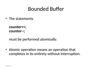
• Thestatements
counter++;
counter--;
must be performed atomically.
• Atomic operation means an operation that
completes in its entirety without interruption.
03/04/25
9.
Bounded Buffer
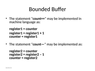
• Thestatement “count++” may be implemented in
machine language as:
register1 = counter
register1 = register1 + 1
counter = register1
• The statement “count—” may be implemented as:
register2 = counter
register2 = register2 – 1
counter = register2
03/04/25
10.
Bounded Buffer
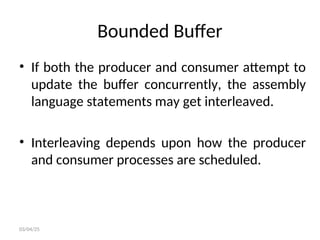
• Ifboth the producer and consumer attempt to
update the buffer concurrently, the assembly
language statements may get interleaved.
• Interleaving depends upon how the producer
and consumer processes are scheduled.
03/04/25
11.
Bounded Buffer
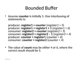
• Assumecounter is initially 5. One interleaving of
statements is:
producer: register1 = counter (register1 = 5)
producer: register1 = register1 + 1 (register1 = 6)
consumer: register2 = counter (register2 = 5)
consumer: register2 = register2 – 1 (register2 = 4)
producer: counter = register1 (counter = 6)
consumer: counter = register2 (counter = 4)
• The value of count may be either 4 or 6, where the
correct result should be 5.
03/04/25
12.
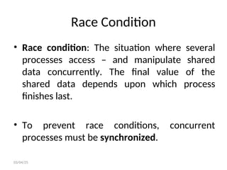
Race Condition
• Racecondition: The situation where several
processes access – and manipulate shared
data concurrently. The final value of the
shared data depends upon which process
finishes last.
• To prevent race conditions, concurrent
processes must be synchronized.
03/04/25
13.
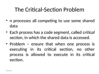
The Critical-Section Problem
•n processes all competing to use some shared
data
• Each process has a code segment, called critical
section, in which the shared data is accessed.
• Problem – ensure that when one process is
executing in its critical section, no other
process is allowed to execute in its critical
section.
03/04/25
14.
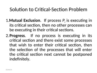
Solution to Critical-SectionProblem
1.Mutual Exclusion. If process Pi is executing in
its critical section, then no other processes can
be executing in their critical sections.
2.Progress. If no process is executing in its
critical section and there exist some processes
that wish to enter their critical section, then
the selection of the processes that will enter
the critical section next cannot be postponed
indefinitely.
03/04/25
15.
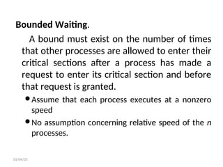
Bounded Waiting.
A boundmust exist on the number of times
that other processes are allowed to enter their
critical sections after a process has made a
request to enter its critical section and before
that request is granted.
Assume that each process executes at a nonzero
speed
No assumption concerning relative speed of the n
processes.
03/04/25
16.
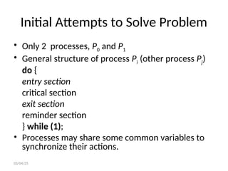
Initial Attempts toSolve Problem
• Only 2 processes, P0 and P1
• General structure of process Pi (other process Pj)
do {
entry section
critical section
exit section
reminder section
} while (1);
• Processes may share some common variables to
synchronize their actions.
03/04/25
17.
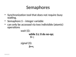
Semaphores
• Synchronization toolthat does not require busy
waiting.
• Semaphore S – integer variable
• can only be accessed via two indivisible (atomic)
operations
wait (S):
while S 0 do no-op;
S--;
signal (S):
S++;
03/04/25
18.
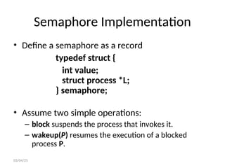
Semaphore Implementation
• Definea semaphore as a record
typedef struct {
int value;
struct process *L;
} semaphore;
• Assume two simple operations:
– block suspends the process that invokes it.
– wakeup(P) resumes the execution of a blocked
process P.
03/04/25
19.
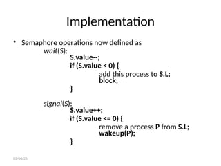
Implementation
• Semaphore operationsnow defined as
wait(S):
S.value--;
if (S.value < 0) {
add this process to S.L;
block;
}
signal(S):
S.value++;
if (S.value <= 0) {
remove a process P from S.L;
wakeup(P);
}
03/04/25
20.
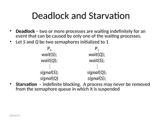
Deadlock and Starvation
•Deadlock – two or more processes are waiting indefinitely for an
event that can be caused by only one of the waiting processes.
• Let S and Q be two semaphores initialized to 1
P0 P1
wait(S); wait(Q);
wait(Q); wait(S);
signal(S); signal(Q);
signal(Q) signal(S);
• Starvation – indefinite blocking. A process may never be removed
from the semaphore queue in which it is suspended
03/04/25
21.
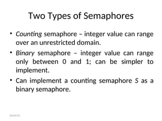
Two Types ofSemaphores
• Counting semaphore – integer value can range
over an unrestricted domain.
• Binary semaphore – integer value can range
only between 0 and 1; can be simpler to
implement.
• Can implement a counting semaphore S as a
binary semaphore.
03/04/25
22.
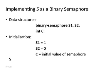
Implementing S asa Binary Semaphore
• Data structures:
binary-semaphore S1, S2;
int C:
• Initialization:
S1 = 1
S2 = 0
C = initial value of semaphore
S
03/04/25
23.
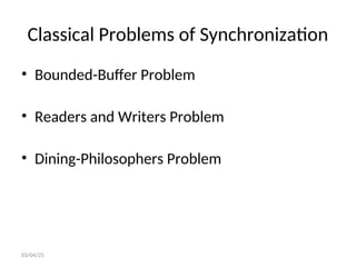
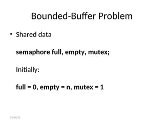
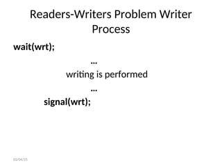
Classical Problems ofSynchronization
• Bounded-Buffer Problem
• Readers and Writers Problem
• Dining-Philosophers Problem
03/04/25
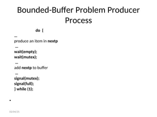
Bounded-Buffer Problem Producer
Process
do{
…
produce an item in nextp
…
wait(empty);
wait(mutex);
…
add nextp to buffer
…
signal(mutex);
signal(full);
} while (1);
•
03/04/25
26.
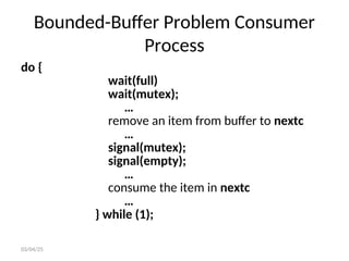
Bounded-Buffer Problem Consumer
Process
do{
wait(full)
wait(mutex);
…
remove an item from buffer to nextc
…
signal(mutex);
signal(empty);
…
consume the item in nextc
…
} while (1);
03/04/25
File Concept
• Contiguouslogical address space
• Types:
– Data
• numeric
• character
• binary
– Program
03/04/25
34.
File Structure
• None- sequence of words, bytes
• Simple record structure
– Lines
– Fixed length
– Variable length
• Complex Structures
– Formatted document
– Relocatable load file
• Can simulate last two with first method by inserting appropriate
control characters.
• Who decides:
– Operating system
– Program
03/04/25
35.
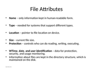
File Attributes
• Name– only information kept in human-readable form.
• Type – needed for systems that support different types.
• Location – pointer to file location on device.
• Size – current file size.
• Protection – controls who can do reading, writing, executing.
• WTime, date, and user identification – data for protection,
security, and usage monitoring.
• Information about files are kept in the directory structure, which is
maintained on the disk.
03/04/25
36.
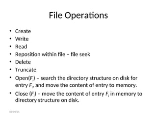
File Operations
• Create
•Write
• Read
• Reposition within file – file seek
• Delete
• Truncate
• Open(Fi) – search the directory structure on disk for
entry Fi, and move the content of entry to memory.
• Close (Fi) – move the content of entry Fi in memory to
directory structure on disk.
03/04/25
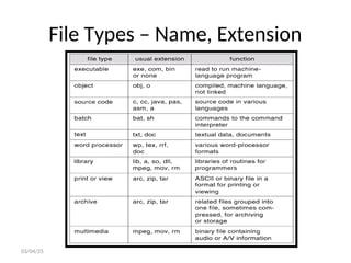
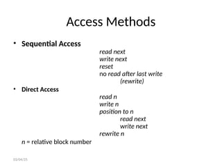
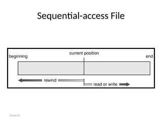
Access Methods
03/04/25
• SequentialAccess
read next
write next
reset
no read after last write
(rewrite)
• Direct Access
read n
write n
position to n
read next
write next
rewrite n
n = relative block number
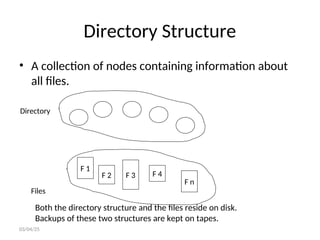
Directory Structure
03/04/25
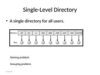
• Acollection of nodes containing information about
all files.
Directory
F 1
F 2 F 3 F 4
F n
Files
Both the directory structure and the files reside on disk.
Backups of these two structures are kept on tapes.
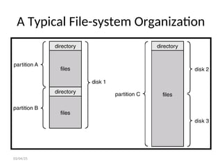
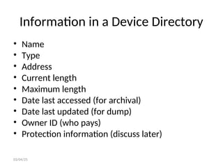
Information in aDevice Directory
• Name
• Type
• Address
• Current length
• Maximum length
• Date last accessed (for archival)
• Date last updated (for dump)
• Owner ID (who pays)
• Protection information (discuss later)
03/04/25
43.
Operations Performed on
Directory
•Search for a file
• Create a file
• Delete a file
• List a directory
• Rename a file
• Traverse the file system
03/04/25
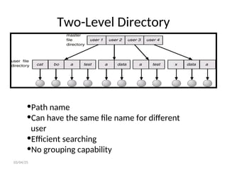
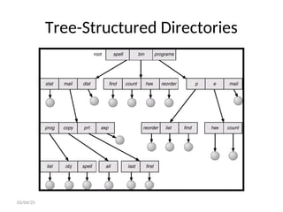
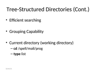
Tree-Structured Directories (Cont.)
•Efficient searching
• Grouping Capability
• Current directory (working directory)
– cd /spell/mail/prog
– type list
03/04/25
48.
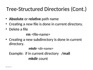
Tree-Structured Directories (Cont.)
•Absolute or relative path name
• Creating a new file is done in current directory.
• Delete a file
rm <file-name>
• Creating a new subdirectory is done in current
directory.
mkdir <dir-name>
Example: if in current directory /mail
mkdir count
03/04/25
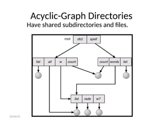
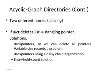
Acyclic-Graph Directories (Cont.)
•Two different names (aliasing)
• If dict deletes list dangling pointer.
Solutions:
– Backpointers, so we can delete all pointers.
Variable size records a problem.
– Backpointers using a daisy chain organization.
– Entry-hold-count solution.
03/04/25
51.
GenerGeneral Graph Directory
(Cont.)alGraph Directory
• How do we guarantee no cycles?
– Allow only links to file not subdirectories.
– Garbage collection.
– Every time a new link is added use a cycle
detection
algorithm to determine whether it is OK.
03/04/25
52.
File Sharing
• Sharingof files on multi-user systems is desirable.
• Sharing may be done through a protection scheme.
• On distributed systems, files may be shared across
a network.
• Network File System (NFS) is a common distributed
file-sharing method.
03/04/25
53.
Protection
• File owner/creatorshould be able to control:
– what can be done
– by whom
• Types of access
– Read
– Write
– Execute
– Append
– Delete
– List
03/04/25
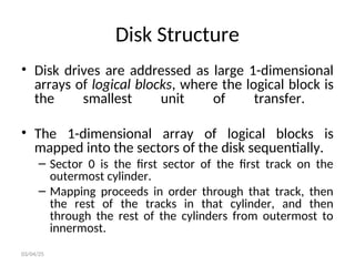
Disk Structure
• Diskdrives are addressed as large 1-dimensional
arrays of logical blocks, where the logical block is
the smallest unit of transfer.
• The 1-dimensional array of logical blocks is
mapped into the sectors of the disk sequentially.
– Sector 0 is the first sector of the first track on the
outermost cylinder.
– Mapping proceeds in order through that track, then
the rest of the tracks in that cylinder, and then
through the rest of the cylinders from outermost to
innermost.
03/04/25
57.
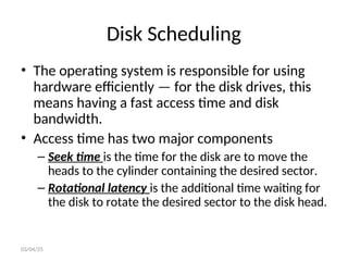
Disk Scheduling
• Theoperating system is responsible for using
hardware efficiently — for the disk drives, this
means having a fast access time and disk
bandwidth.
• Access time has two major components
– Seek time is the time for the disk are to move the
heads to the cylinder containing the desired sector.
– Rotational latency is the additional time waiting for
the disk to rotate the desired sector to the disk head.
03/04/25
58.
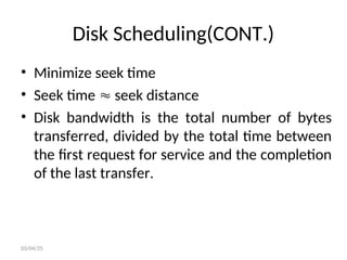
Disk Scheduling(CONT.)
• Minimizeseek time
• Seek time seek distance
• Disk bandwidth is the total number of bytes
transferred, divided by the total time between
the first request for service and the completion
of the last transfer.
03/04/25
59.
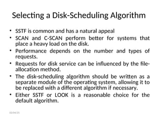
Selecting a Disk-SchedulingAlgorithm
• SSTF is common and has a natural appeal
• SCAN and C-SCAN perform better for systems that
place a heavy load on the disk.
• Performance depends on the number and types of
requests.
• Requests for disk service can be influenced by the file-
allocation method.
• The disk-scheduling algorithm should be written as a
separate module of the operating system, allowing it to
be replaced with a different algorithm if necessary.
• Either SSTF or LOOK is a reasonable choice for the
default algorithm.
03/04/25
60.
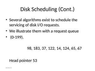
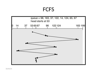
Disk Scheduling (Cont.)
•Several algorithms exist to schedule the
servicing of disk I/O requests.
• We illustrate them with a request queue
• (0-199).
98, 183, 37, 122, 14, 124, 65, 67
Head pointer 53
03/04/25
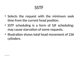
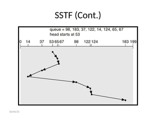
SSTF
• Selects therequest with the minimum seek
time from the current head position.
• SSTF scheduling is a form of SJF scheduling;
may cause starvation of some requests.
• Illustration shows total head movement of 236
cylinders.
03/04/25
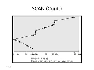
SCAN
• The diskarm starts at one end of the disk, and
moves toward the other end, servicing
requests until it gets to the other end of the
disk, where the head movement is reversed
and servicing continues.
• Sometimes called the elevator algorithm.
• Illustration shows total head movement of 208
cylinders.
03/04/25
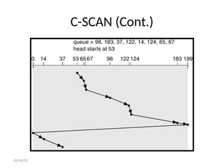
C-SCAN
• Provides amore uniform wait time than SCAN.
• The head moves from one end of the disk to
the other. servicing requests as it goes. When
it reaches the other end, however, it
immediately returns to the beginning of the
disk, without servicing any requests on the
return trip.
• Treats the cylinders as a circular list that wraps
around from the last cylinder to the first one.
03/04/25
C-LOOK
• Version ofC-SCAN
• Arm only goes as far as the last request in
each direction, then reverses direction
immediately, without first going all the way to
the end of the disk.
03/04/25
Deadlocks
• System Model
•Deadlock Characterization
• Methods for Handling Deadlocks
• Deadlock Prevention
• Deadlock Avoidance
• Deadlock Detection
• Recovery from Deadlock
• Combined Approach to Deadlock Handling
03/04/25
72.
The Deadlock Problem
•A set of blocked processes each holding a resource and
waiting to acquire a resource held by another process in
the set.
• Example
– System has 2 tape drives.
– P1 and P2 each hold one tape drive and each needs another one.
• Example
– semaphores A and B, initialized to 1
P0 P1
wait (A); wait(B)
wait (B); wait(A)
03/04/25
73.
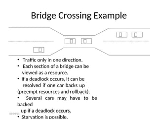
Bridge Crossing Example
03/04/25
•Traffic only in one direction.
• Each section of a bridge can be
viewed as a resource.
• If a deadlock occurs, it can be
resolved if one car backs up
(preempt resources and rollback).
• Several cars may have to be
backed
up if a deadlock occurs.
• Starvation is possible.
74.
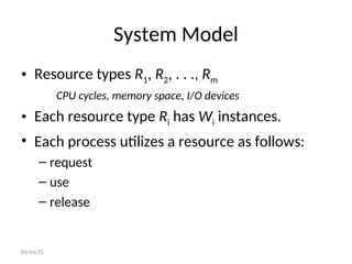
System Model
• Resourcetypes R1, R2, . . ., Rm
CPU cycles, memory space, I/O devices
• Each resource type Ri has Wi instances.
• Each process utilizes a resource as follows:
– request
– use
– release
03/04/25
75.
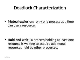
Deadlock Characterization
• Mutualexclusion: only one process at a time
can use a resource.
• Hold and wait: a process holding at least one
resource is waiting to acquire additional
resources held by other processes.
03/04/25
76.
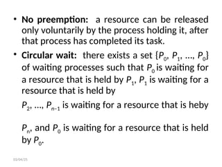
• No preemption:a resource can be released
only voluntarily by the process holding it, after
that process has completed its task.
• Circular wait: there exists a set {P0, P1, …, P0}
of waiting processes such that P0 is waiting for
a resource that is held by P1, P1 is waiting for a
resource that is held by
P2, …, Pn–1 is waiting for a resource that is heby
Pn, and P0 is waiting for a resource that is held
by P0.
03/04/25
77.
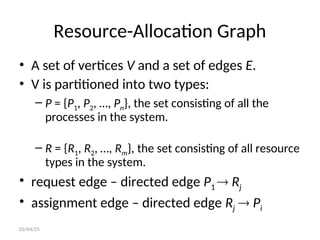
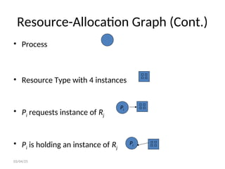
Resource-Allocation Graph
• Aset of vertices V and a set of edges E.
• V is partitioned into two types:
– P = {P1, P2, …, Pn}, the set consisting of all the
processes in the system.
– R = {R1, R2, …, Rm}, the set consisting of all resource
types in the system.
• request edge – directed edge P1 Rj
• assignment edge – directed edge Rj Pi
03/04/25
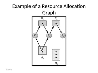
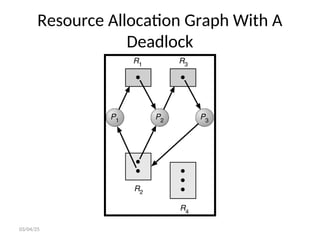
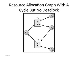
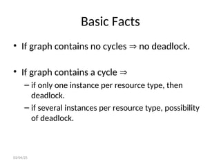
Basic Facts
• Ifgraph contains no cycles no deadlock.
• If graph contains a cycle
– if only one instance per resource type, then
deadlock.
– if several instances per resource type, possibility
of deadlock.
03/04/25
83.
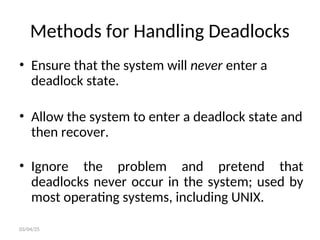
Methods for HandlingDeadlocks
• Ensure that the system will never enter a
deadlock state.
• Allow the system to enter a deadlock state and
then recover.
• Ignore the problem and pretend that
deadlocks never occur in the system; used by
most operating systems, including UNIX.
03/04/25
84.
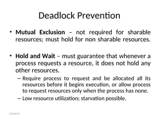
Deadlock Prevention
• MutualExclusion – not required for sharable
resources; must hold for non sharable resources.
• Hold and Wait – must guarantee that whenever a
process requests a resource, it does not hold any
other resources.
– Require process to request and be allocated all its
resources before it begins execution, or allow process
to request resources only when the process has none.
– Low resource utilization; starvation possible.
03/04/25
85.
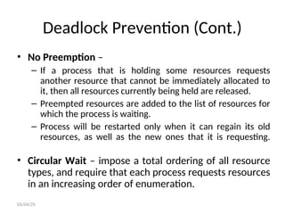
Deadlock Prevention (Cont.)
•No Preemption –
– If a process that is holding some resources requests
another resource that cannot be immediately allocated to
it, then all resources currently being held are released.
– Preempted resources are added to the list of resources for
which the process is waiting.
– Process will be restarted only when it can regain its old
resources, as well as the new ones that it is requesting.
• Circular Wait – impose a total ordering of all resource
types, and require that each process requests resources
in an increasing order of enumeration.
03/04/25
86.
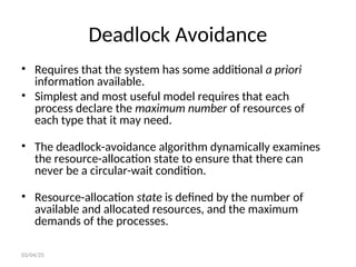
Deadlock Avoidance
• Requiresthat the system has some additional a priori
information available.
• Simplest and most useful model requires that each
process declare the maximum number of resources of
each type that it may need.
• The deadlock-avoidance algorithm dynamically examines
the resource-allocation state to ensure that there can
never be a circular-wait condition.
• Resource-allocation state is defined by the number of
available and allocated resources, and the maximum
demands of the processes.
03/04/25
87.
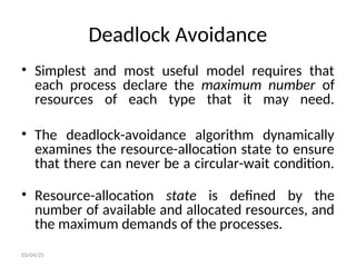
Deadlock Avoidance
• Simplestand most useful model requires that
each process declare the maximum number of
resources of each type that it may need.
• The deadlock-avoidance algorithm dynamically
examines the resource-allocation state to ensure
that there can never be a circular-wait condition.
• Resource-allocation state is defined by the
number of available and allocated resources, and
the maximum demands of the processes.
03/04/25
88.
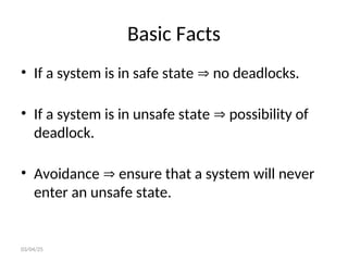
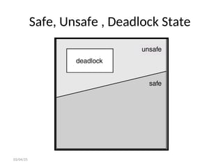
Basic Facts
• Ifa system is in safe state no deadlocks.
• If a system is in unsafe state possibility of
deadlock.
• Avoidance ensure that a system will never
enter an unsafe state.
03/04/25
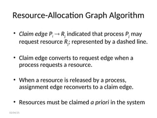
Resource-Allocation Graph Algorithm
•Claim edge Pi Rj indicated that process Pj may
request resource Rj; represented by a dashed line.
• Claim edge converts to request edge when a
process requests a resource.
• When a resource is released by a process,
assignment edge reconverts to a claim edge.
• Resources must be claimed a priori in the system
03/04/25
91.
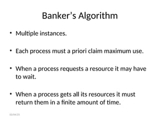
Banker’s Algorithm
• Multipleinstances.
• Each process must a priori claim maximum use.
• When a process requests a resource it may have
to wait.
• When a process gets all its resources it must
return them in a finite amount of time.
03/04/25
92.
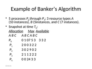
Example of Banker’sAlgorithm
• 5 processes P0 through P4; 3 resource types A
(10 instances), B (5instances, and C (7 instances).
• Snapshot at time T0:
Allocation Max Available
A B C A B C A B C
P0 0 1 07 5 3 3 3 2
P1 2 0 0 3 2 2
P2 3 0 2 9 0 2
P3 2 1 1 2 2 2
P4 0 0 24 3 3
03/04/25
93.
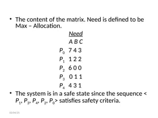
• The contentof the matrix. Need is defined to be
Max – Allocation.
Need
A B C
P0 7 4 3
P1 1 2 2
P2 6 0 0
P3 0 1 1
P4 4 3 1
• The system is in a safe state since the sequence <
P1, P3, P4, P2, P0> satisfies safety criteria.
03/04/25
94.
Example P1 Request(1,0,2) (Cont.)
• Check that Request Available (that is, (1,0,2) (3,3,2) true.
Allocation Need Available
A B C A B C A B C
P0 0 1 0 7 4 3 2 3 0
P1 3 0 2 0 2 0
P2 3 0 1 6 0 0
P3 2 1 1 0 1 1
P4 0 0 2 4 3 1
• Executing safety algorithm shows that sequence <P1, P3, P4, P0, P2>
satisfies safety requirement.
• Can request for (3,3,0) by P4 be granted?
• Can request for (0,2,0) by P0 be granted?
03/04/25
95.
Deadlock Detection
• Allowsystem to enter deadlock state
• Detection algorithm
• Recovery scheme
03/04/25
96.
Detection Algorithm
Let Workand Finish be vectors of length m and n,
respectively Initialize:
1.(a) Work = Available
(b)For i = 1,2, …, n, if Allocationi 0, then
Finish[i] = false;otherwise, Finish[i] = true.
2. Find an index i such that both:
(a)Finish[i] == false
(b)Requesti Work
3. If no such i exists, go to step 4.
03/04/25
97.
Work = Work+ Allocationi
Finish[i] = true
go to step 2.
4.If Finish[i] == false, for some i, 1 i n, then
the system is in deadlock state. Moreover, if
Finish[i] == false, then Pi is deadlocked.
03/04/25

![Bounded-Buffer
#define BUFFER_SIZE 10
typedef struct {
. . .
} item;
item buffer[BUFFER_SIZE];
int in = 0;
int out = 0;
int counter = 0;
03/04/25](https://image.slidesharecdn.com/operating-system-2-250304100046-5f6690d1/85/Chapter-5-Process-Synchronization-OS-ppt-5-320.jpg)
![Bounded-Buffer
03/04/25
• Producer process
item nextProduced;
while (1) {
while (counter == BUFFER_SIZE)
; /* do nothing */
buffer[in] = nextProduced;
in = (in + 1) % BUFFER_SIZE;
counter++;
}](https://image.slidesharecdn.com/operating-system-2-250304100046-5f6690d1/85/Chapter-5-Process-Synchronization-OS-ppt-6-320.jpg)
![Bounded-Buffer
03/04/25
• Consumer process
item nextConsumed;
while (1) {
while (counter == 0)
; /* do nothing */
nextConsumed = buffer[out];
out = (out + 1) % BUFFER_SIZE;
counter--;
}](https://image.slidesharecdn.com/operating-system-2-250304100046-5f6690d1/85/Chapter-5-Process-Synchronization-OS-ppt-7-320.jpg)
![Dining-Philosophers Problem
03/04/25
Shared data
semaphore chopstick[5];
Initially all values are 1](https://image.slidesharecdn.com/operating-system-2-250304100046-5f6690d1/85/Chapter-5-Process-Synchronization-OS-ppt-29-320.jpg)
![Dining-Philosophers Problem
• Philosopher i:
do {
wait(chopstick[i])
wait(chopstick[(i+1) % 5])
…
eat
…
signal(chopstick[i]);
signal(chopstick[(i+1) % 5]);
…
think
…
} while (1);
03/04/25](https://image.slidesharecdn.com/operating-system-2-250304100046-5f6690d1/85/Chapter-5-Process-Synchronization-OS-ppt-30-320.jpg)


![Detection Algorithm
Let Work and Finish be vectors of length m and n,
respectively Initialize:
1.(a) Work = Available
(b)For i = 1,2, …, n, if Allocationi 0, then
Finish[i] = false;otherwise, Finish[i] = true.
2. Find an index i such that both:
(a)Finish[i] == false
(b)Requesti Work
3. If no such i exists, go to step 4.
03/04/25](https://image.slidesharecdn.com/operating-system-2-250304100046-5f6690d1/85/Chapter-5-Process-Synchronization-OS-ppt-96-320.jpg)
![Work = Work + Allocationi
Finish[i] = true
go to step 2.
4.If Finish[i] == false, for some i, 1 i n, then
the system is in deadlock state. Moreover, if
Finish[i] == false, then Pi is deadlocked.
03/04/25](https://image.slidesharecdn.com/operating-system-2-250304100046-5f6690d1/85/Chapter-5-Process-Synchronization-OS-ppt-97-320.jpg)