Downloaded 24 times
![Addressing Modes
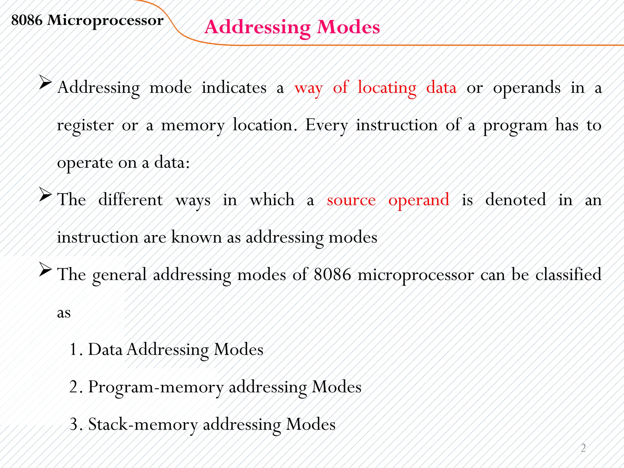
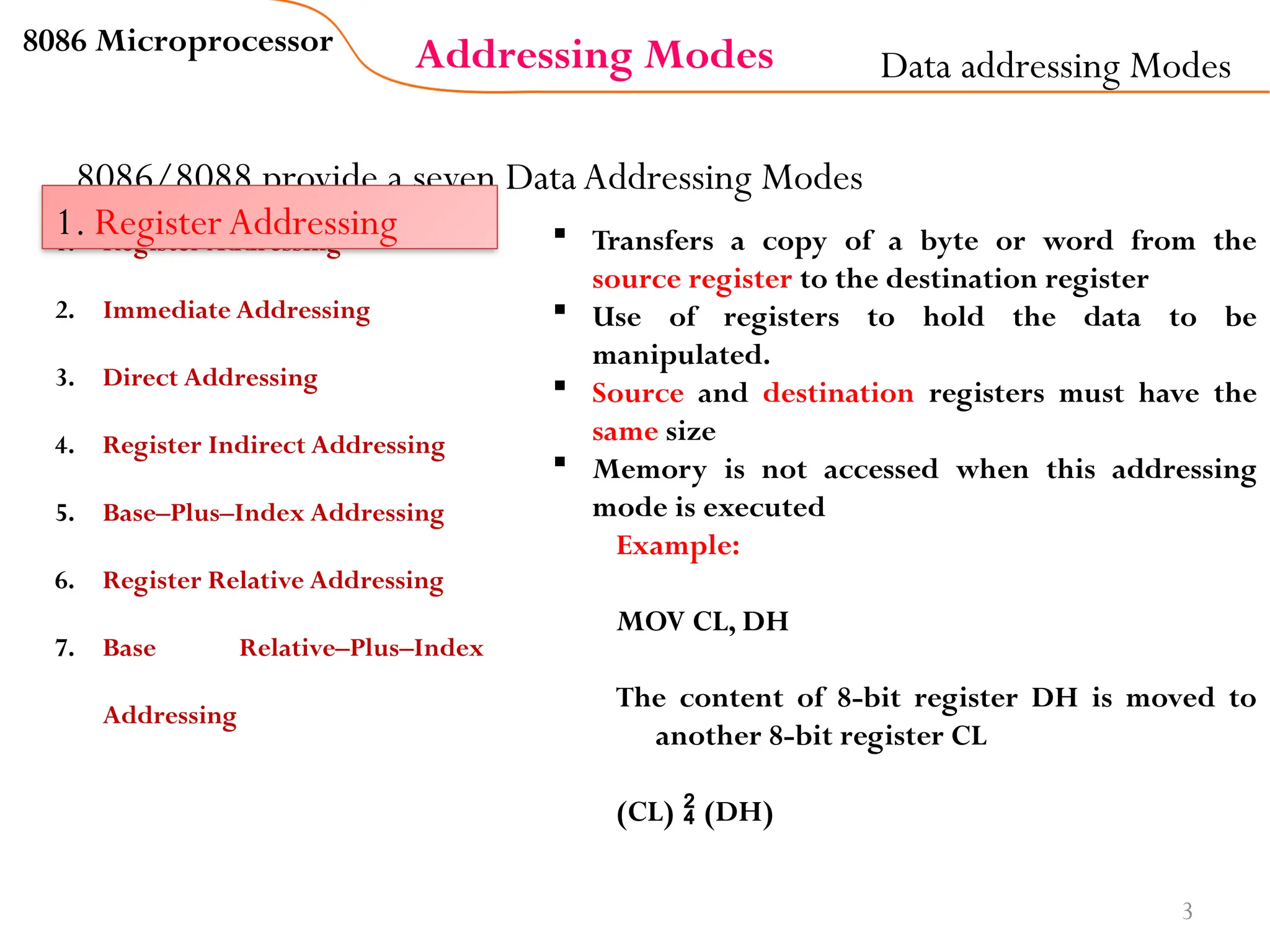
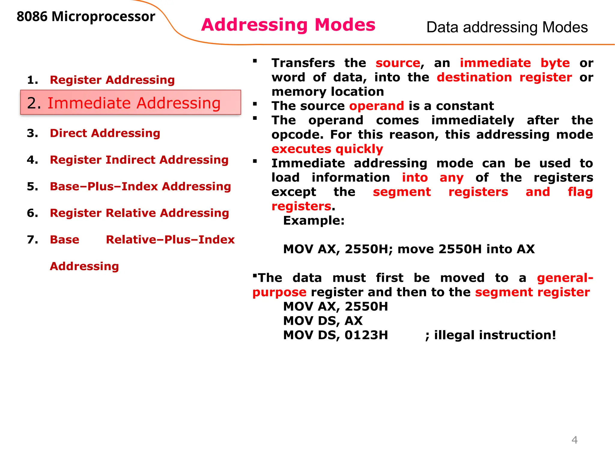
8086 Microprocessor
5
Data addressing Modes
1. Register Addressing
2. Immediate Addressing
3. Direct Addressing
4. Register Indirect Addressing
5. Base–Plus–Index Addressing
6. Register Relative Addressing
7. Base Relative–Plus–Index
Addressing
3. Direct Addressing
Moves a byte or word between a memory
location and a register.
The data is in some memory location(s) and
the address of the data in memory comes
immediately after the instruction.
This address is the offset address.
Example:
MOV AX, [2400] ; move contents of
DS:2400H into AX
The physical address is calculated by
combining the contents of offset location
2400 with DS
i.e. DS:2400
If DS is given 1512H
Physical address
= 15120+2400=17520H](https://image.slidesharecdn.com/chapter4addressingmode-250110133901-94ed4253/75/Chapter-4-addressing-mode-in-microprocessor-pptx-5-2048.jpg)
![Addressing Modes
8086 Microprocessor
6
Data addressing Modes
1. Register Addressing
2. Immediate Addressing
3. Direct Addressing
4. Register Indirect Addressing
5. Base–Plus–Index Addressing
6. Register Relative Addressing
7. Base Relative–Plus–Index
Addressing
4. Register-Indirect Addressing
Transfers a byte or word between a register and a
memory location addressed by an index or base
register
The address of the memory location where the
operand resides is held by a register
The registers used for this purpose are SI, DI, and
BX, BP
They must be combined with DS in order to
generate the 20-bit physical address
Example:
MOV AX, [BX] ; moves into AX the
contents of the memory location pointed to
by DS:BX, 1000:1234
The physical address is calculated as
1000x10+1234=11234H](https://image.slidesharecdn.com/chapter4addressingmode-250110133901-94ed4253/75/Chapter-4-addressing-mode-in-microprocessor-pptx-6-2048.jpg)
![Addressing Modes
8086 Microprocessor
7
Data addressing Modes
1. Register Addressing
2. Immediate Addressing
3. Direct Addressing
4. Register Indirect Addressing
5. Base–Plus–Index Addressing
6. Register Relative Addressing
7. Base Relative–Plus–Index
Addressing
5. Base–Plus–Index Addressing
Transfers a byte or word between a register
and the memory location addressed by a
base register (BP or BX) plus an index
register (DI or SI).
Combining based and indexed addressing
modes. One base register and one index
register are used
Example:
MOV [BX+DI], CL ; move contents of CL
into DS:BX+DI
Physical Address = DSx10 + BX+DI
MOV [BP+SI], AL ; move contents of AL
into SS:BP+SI
Physical Address = SSx10 + BP+SI](https://image.slidesharecdn.com/chapter4addressingmode-250110133901-94ed4253/75/Chapter-4-addressing-mode-in-microprocessor-pptx-7-2048.jpg)
![Addressing Modes
8086 Microprocessor
8
Data addressing Modes
1. Register Addressing
2. Immediate Addressing
3. Direct Addressing
4. Register Indirect Addressing
5. Base–Plus–Index Addressing
6. Register Relative Addressing
7. Base Relative–Plus–Index
Addressing
6. Register Relative Addressing
Moves a byte or word between a register
and the memory location addressed by an
index or base register plus a displacement.
The data in a segment of memory are
addressed by adding the displacement to
the contents of a base or an index register
(BP, BX, DI, or SI).
Example:
MOV AX, [BX+4] ; move
contents of DS:BX+4 into AX
Physical Address = DSx10 + BX+4](https://image.slidesharecdn.com/chapter4addressingmode-250110133901-94ed4253/75/Chapter-4-addressing-mode-in-microprocessor-pptx-8-2048.jpg)
![Addressing Modes
8086 Microprocessor
9
Data addressing Modes
1. Register Addressing
2. Immediate Addressing
3. Direct Addressing
4. Register Indirect Addressing
5. Base–Plus–Index Addressing
6. Register Relative Addressing
7. Base Relative–Plus–Index
Addressing
The base relative-plus-index addressing
mode is similar to the base-plus-index
addressing mode, but adds a displacement
besides using a base register and an index
register to form the memory address.
This type of addressing mode often
addresses a two-dimensional array of
memory data.
The data in a segment of memory are
addressed by adding the displacement to
the contents of a base and an index register
(BP, BX, DI, or SI).
Example:
MOV [BX+DI+1], AX ; move
contents of AX into DS:BX+DI+1
Physical Address = DSx10 +
BX+DI+1H](https://image.slidesharecdn.com/chapter4addressingmode-250110133901-94ed4253/75/Chapter-4-addressing-mode-in-microprocessor-pptx-9-2048.jpg)
![17
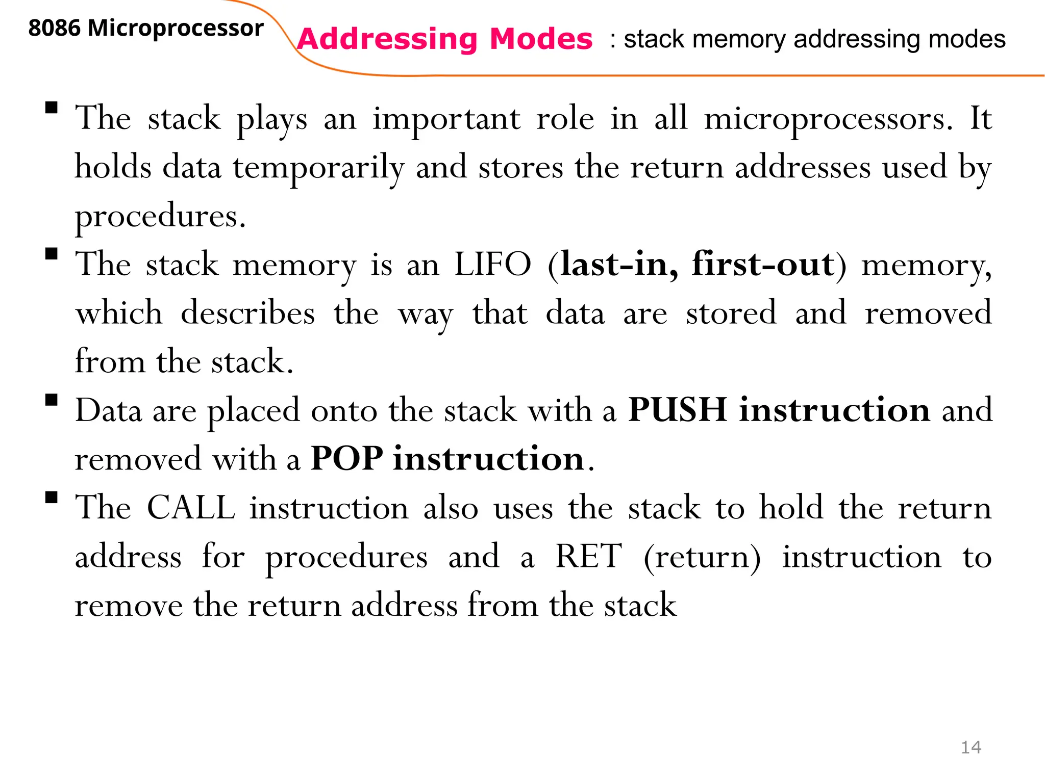
POPF Removes a word from the stack and places it into the flag register
POPFD Removes a doubleword from the stack and places it into the EFLAG register
PUSHF Copies the flag register to the stack
PUSHFD Copies the EFLAG register to the stack
PUSH AX Copies the AX register to the stack
POP BX Removes a word from the stack and places it into the BX register
PUSH DS Copies the DS register to the stack
PUSH 1234H Copies a word-sized 1234H to the stack
POP CS This instruction is illegal
PUSH WORD PTR[BX] Copies the word contents of the data segment memory location addressed by BX onto
the stack
PUSHA Copies AX, CX, DX, BX, SP, BP, DI, and SI to the stack
POPA Removes the word contents for the following registers from the stack: SI, DI, BP
, SP, BX, DX, CX,
and AX
PUSHAD Copies EAX, ECX, EDX, EBX, ESP, EBP, EDI, and ESI to the stack
POPAD Removes the doubleword contents for the following registers from the stack: ESI, EDI, EBP
, ESP
, EBX, EDX, ECX, and EAX
POP EAX Removes a doubleword from the stack and places it into the EAX register
POP RAX Removes a quadword from the stack and places it into the RAC register (64-bit mode)
PUSH EDI Copies EDI to the stack
PUSH RSI Copies RSI into the stack (64-bit mode)
PUSH QWORD PTR[RDX] Copies the quadword contents of the memory location addressed](https://image.slidesharecdn.com/chapter4addressingmode-250110133901-94ed4253/75/Chapter-4-addressing-mode-in-microprocessor-pptx-17-2048.jpg)


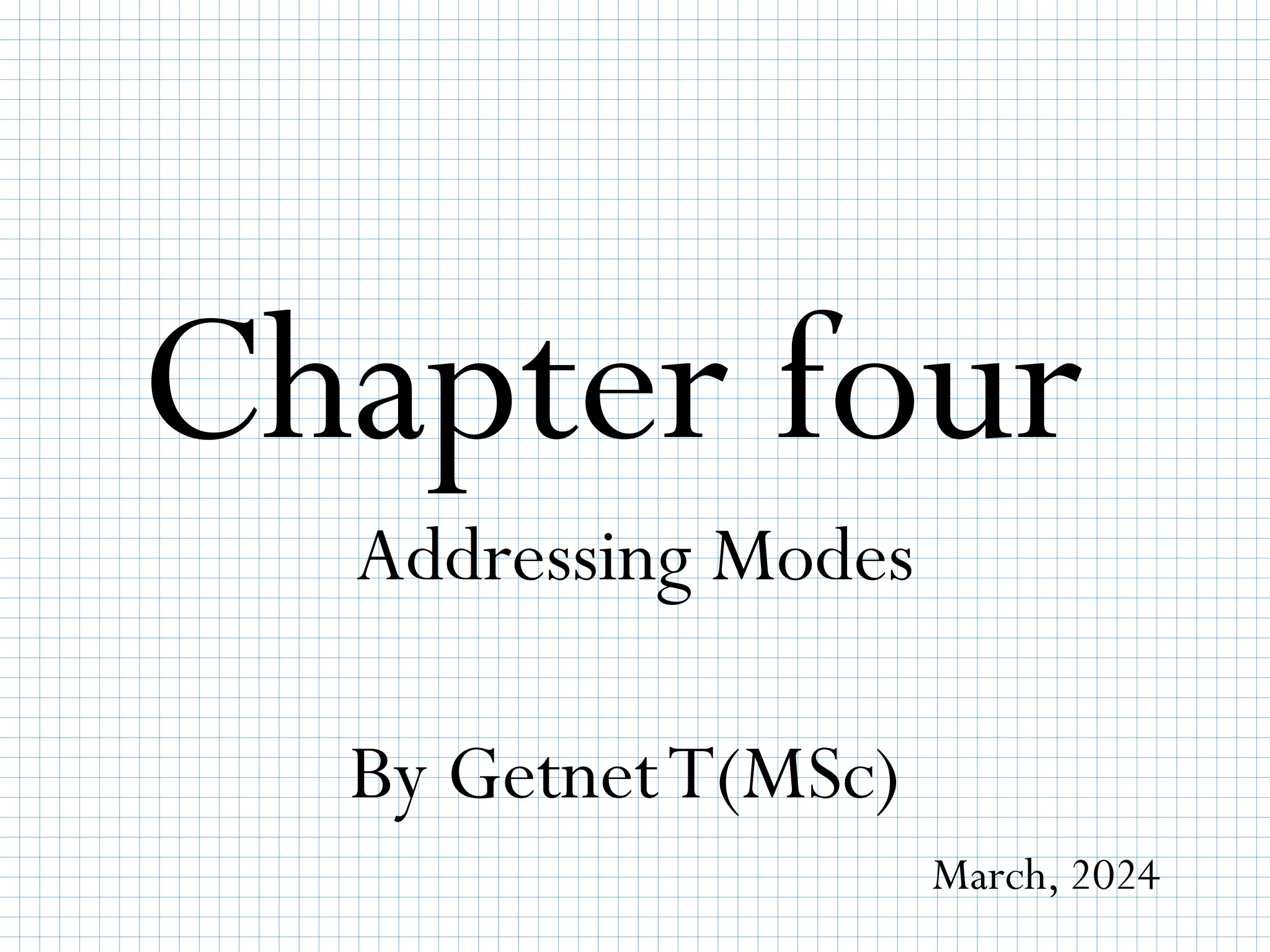
The document explains various addressing modes of the 8086 microprocessor, which describe how to locate data or operands in memory or registers. It categorizes these modes into data, program-memory, and stack-memory addressing modes, detailing seven data addressing modes and their functionalities. Additionally, it covers how stack operations work, emphasizing the importance of push and pop instructions in managing stack memory.


![Vibe Coding vs. Spec-Driven Development [Free Meetup]](https://cdn.slidesharecdn.com/ss_thumbnails/vibecodingvsspecdrivendevelopment-251209105622-43f455e7-thumbnail.jpg?width=640&height=640&fit=bounds)


